check engine ACURA INTEGRA 1998 Service Repair Manual
[x] Cancel search | Manufacturer: ACURA, Model Year: 1998, Model line: INTEGRA, Model: ACURA INTEGRA 1998Pages: 1680, PDF Size: 53.14 MB
Page 1059 of 1680

Troubleshooting
Tips and Precautions
Never try to disconnect connectors by pulling on their
wires; pull on lhe connector halves instead.
Alwavs reinstall Dlastic covers.
Before connecting connectors, make sure the termi-
nals are in Dlace and not bent.
a Check lor loose retainer and rubber seals.
The backs of some connectors are packed with
grease. Add grease if needed. lf the grease is contami-
nated, reolace it.
(cont'd )
RETAINER
K
Bef ore Troubleshooting
a Check applicable tuses in the appropriate fuse/relay
box.
Check the battery for damage, state of charge, and
clean and tight connections.
Check the alternator belt tension.
CAUTION:
a Do not quick-charge a battely unless the battery
ground cable has been disconnected. otherwise
you will damage the alternator diod€s.
a Do not attempt to crank the engine with the bat-
tery ground cable loosely connected or you willse-
verely damage the wiring.
a The originsl radio has a coded theft plotection cir-
cuit. Be sure to get the customel's code numbel
before- disconnecting the battsry.- removing the No. 47 (7.5 A) fuse from tho
under-hood luse/relay box.- removing the radio.
Atter service. leconnect Dower to the radio and
tum it on. When the word "CODE" is displayed,
enter the customer's 5-digit code to restore radio
ooeration.
Handling Connectors
a Make sure the connectors are clean and have no loose
wire terminals.
a Make sure multiple cavity connectors are packed with
grease (except watertight connectors).
a All connectors have push-down release type locks.
LOCKING TAB
LOCKING TAB
Some connectors have a clip on their side used to at-
tach them to a mount bracket on the body or on
another component. This clip has a pull type lock.
Some mounted connectors cannot be disconnected
unless you tirst release the lock and remove the con-
nector from its bracket.
LOCKINGPAWL ONOTHERHALF OFCONNECTORPull todisengageBRACKET
Page 1080 of 1680
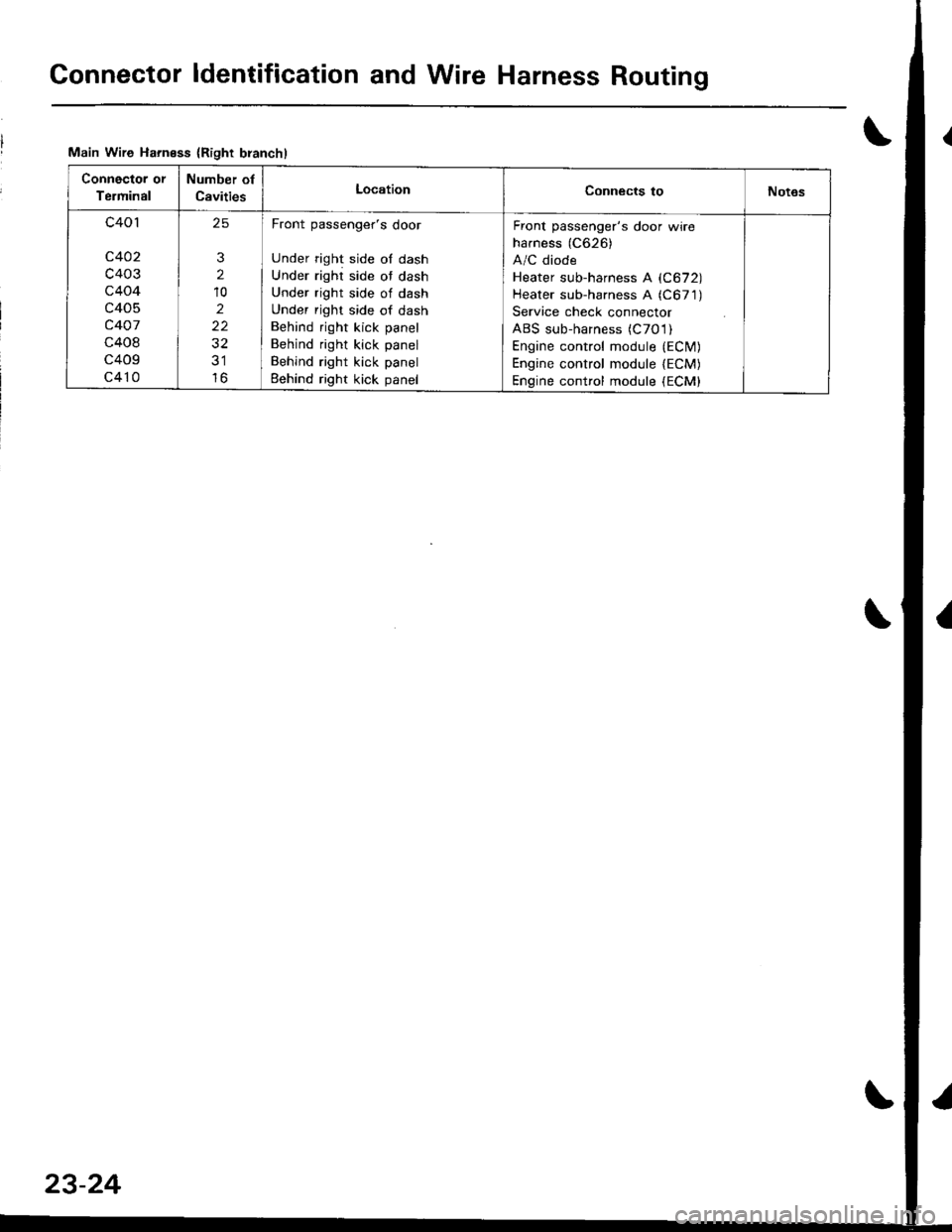
Gonnector ldentification and Wire Harness Routing
Main Wire Harness {Right branchl
Connector or
Terminal
Number of
CavitiesLocationConnects toNot6s
c401
c402
c403
c404
c405
c407
c408
c409
c410
25
3
2
10
2
22
32
lo
Front passenger's door
Under right side of dash
Under right side ot dash
Under right side of dash
Under right side of dash
Behind right kick panel
Behind right kick panel
Behind right kick panel
Eehind right kick panel
Front passenger's door wire
harness (C626)
A/C diode
Heater sub-harness A (C672)
Heater sub-harness A (C671)
Service check connector
ABS sub-harness (C7O l)
Engine control module {ECfM)Engine control module lECM)Engine contfol module (ECM)
23-24
Page 1133 of 1680
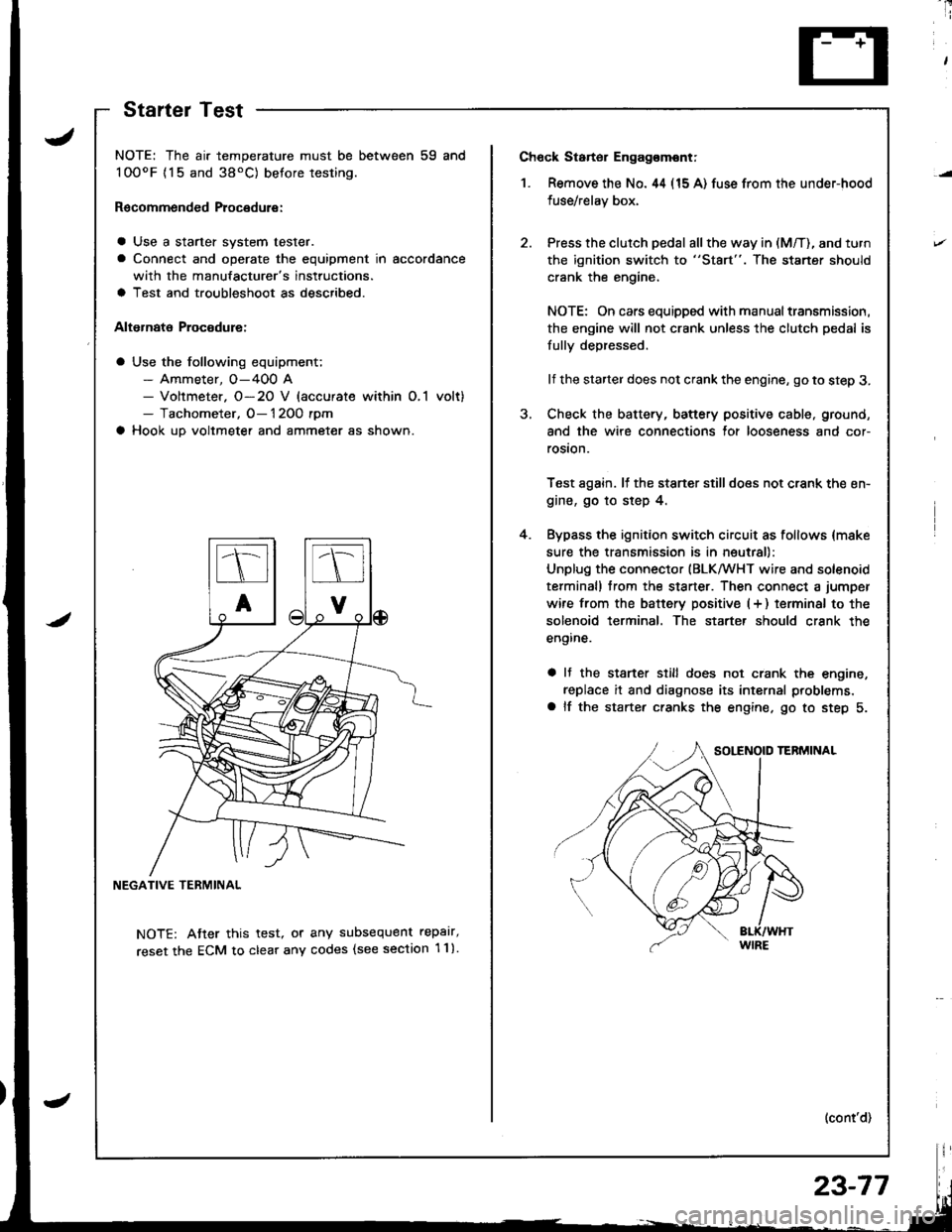
Ch6ck Starter Engag€mont;
1. Remove the No. 44 (15 A) fuse from the under-hood
fuse/relay box,
Press the clutch pedal all the way in (M/T), and turn
the ignition switch to "St8rt". The staner should
crank the engine,
NOTE: On cars equipped with manual transmission,
the engine will not crank unless the clutch pedal is
fully depressed.
lf the starter does not crank the engine, go to step 3.
Check the battery, battery positive cable, ground,
and the wire connections for looseness and cor-
rosion.
Test again. lf the stsner stilldoes not crank the en-
gine, go to step 4.
Bypass the ignition switch circuit as follows {make
sure the transmission is in neutral)
Unplug the connector (BLKMHT wire and solenoid
terminal) trom the staner. Then connect a jumper
wire from the batterv positive (+ ) terminal to the
solenoid terminal. The starter should crank the
engine.
a It the stsrter still does not crank the engine,
replace it and diagnose its internal problems,
a lf the starter cranks the engine. go to step 5.
(cont'd)
4.
NOTE: The air temperature must be between 59 and
100oF {15 and 38'C) betore testing.
Recommended Procedure:
a Use a starter system tester.
a Connect and operate the equipment in accordance
with the manufacturer's instructions.
a Test and troubleshoot as described.
Alternate Procodure:
a Use the following equipment;- Ammeter, O-400 A- Voltmeter. O-20 V (accurate within O,1 volt)- Tachometer, O- 1 2OO rpm
a Hook up voltmeter and ammeter as shown.
NEGATIVE TERMINAL
NOTE: Atter this test, or any subsequent repalr,
reset the ECM to clear any codes (see section 1 1).
StartelTest
23-77
Page 1134 of 1680
Starting System
Starter Test (cont'dl
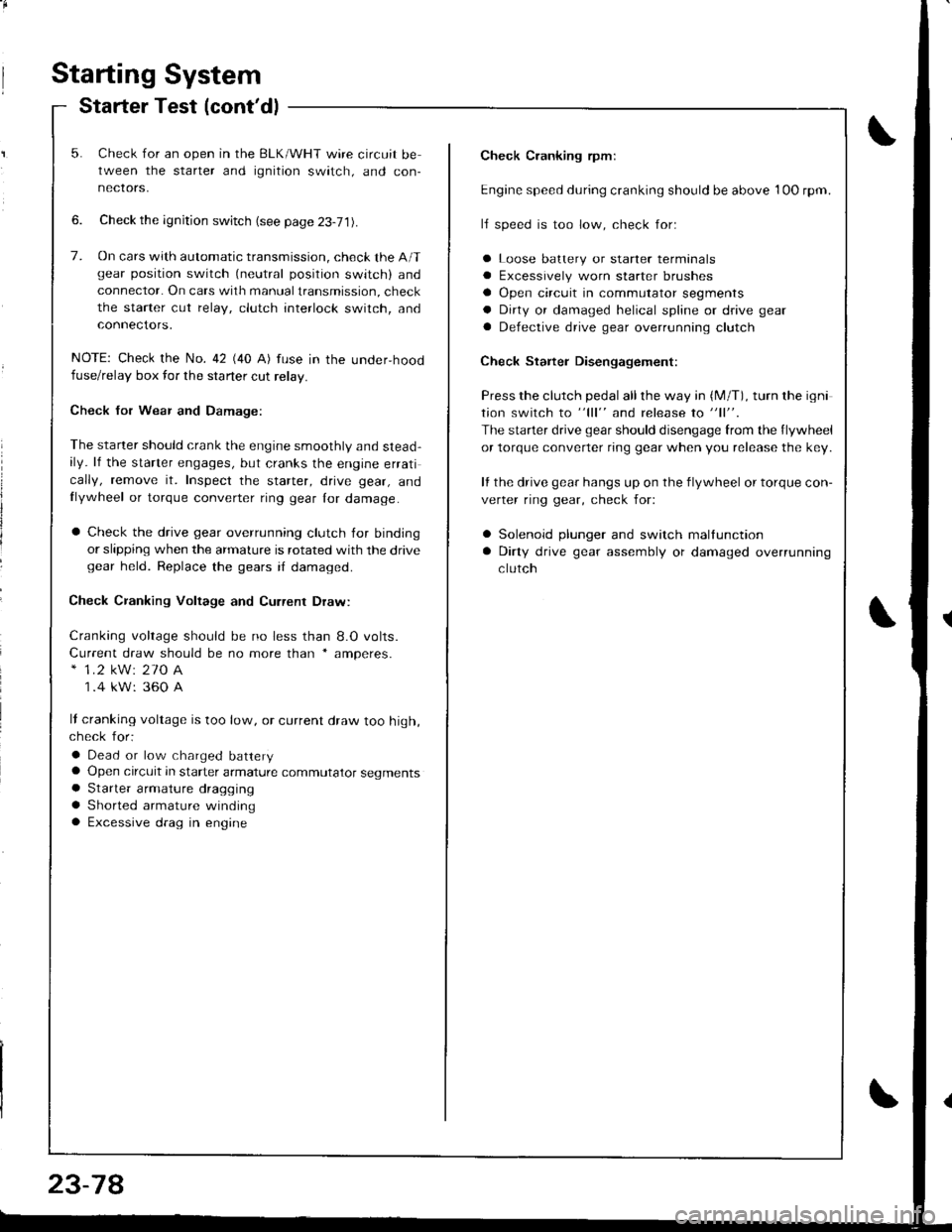
Check Cranking rpmr
Engine speed during cranking should be above 1OO rpm.
lJ speed is too low, check for:
a Loose batlery or starter terminals
a Excessively worn starter brushes
a Open circuit in commutator segments
a Dirty or damaged helical spline or drive gear
a Defective drive gear overrunning clutch
Check Starter Disengagement:
Press the clutch pedal all the way in (M/T), turn rhe igni
tion switch to "lll" and release to "11".
The starter drive gear should disengage from the flywheel
or torque converter ring gear when you release the key.
It the drive gear hangs up on the flywheel or torque con-
verter ring gear, check for:
a Solenoid plunger and switch mallunction
a Dirty drive gear assembly or damaged overrunning
clutch
5. Check for an open in the BLK/WHT wire circuit be
tween the starter and ignition switch, and con-
necrors,
6. Check the ignition switch (see page 23-71).
7. On cars with automatic transmission, check the A/Tgear position switch (neutral position switch) and
connector. On cars with manualtransmission, check
the starter cut relay, clutch interlock switch, and
connectors.
NOTE: Check the No. 42 (40 A) fuse in the under,hoodfuse/relay box for the starter cut relay.
Check Jor Wear and Damage:
The starter should crank the engine smoothly and stead,ily. lf the starter engages, but cranks the engine errati
cally, remove it. Inspect the starter, drive gear, andllywheel or torque converter ring gear lor damage.
a Check the drive gear overrunning clutch for binding
or slipping when the armature is rotated with the drivegear held. Replace the gears i{ damaged.
Check CJanking Voltage and Current Draw:
Cranking voltage should be no less than 8.O volts.
Current draw should be no more than * amperes.* 1.2 kW: 27O A
1 .4 kW: 360 A
It cranking voltage is too low, or current draw too high,check for:
a Dead or low charged batterya Open circuit in starter armature commutator segmentsa Starter armalure dragging
a Shorted armature windinga Excessive drag in engine
Page 1158 of 1680
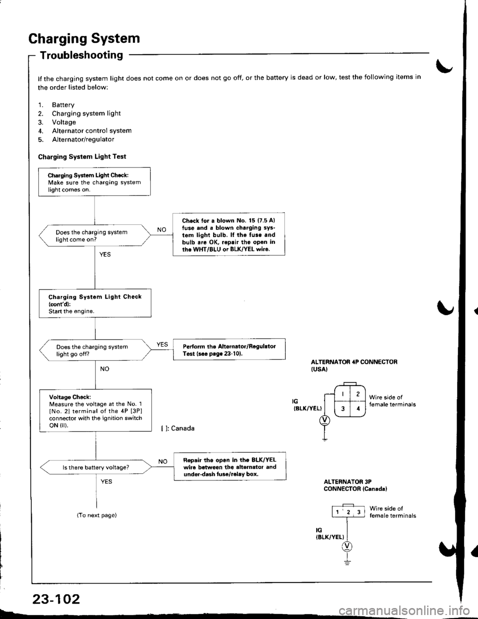
Charging System
Troubleshooting
It the charging system light does not come on or does not go off, or the battery is dead or low, test the following items in
the order listed below:
1. Battery
2. Charging system light
3. Voltage
4. Alternator control system
5. Alternator/regulator
Charging System Light Test
ALTERNATOR'P CONNECTORIUSAI
IGIBLK/YEL)
Wire side offemale terminals
Wire side offemale terminals
ALTERNATOR 3PCONNECTOR lCanadal
Charging System Light Check:Make sure the charging systemlight comes on.
Ch€ck tor a blown No. 15 (7.5 A)
tuse and . blown charging sys-
tem light bulb. ll the fuse andbulb are OK, .eptir tho open inlhe WHT/BLU or BLK/YEL wire.
Does the charging systemlight come on?
Ch.rging System Light Check(cont'd):
Start the engine.
Pertorm the Ahernator/RegulstolTest (s€. prge 23-101,Does the charging systemlight go off?
Voltago Check:Measure the voltage at the No. 1
lNo. 2l terminal of the 4P [3P]connector with tho ignition switchoN {lr).
Repair tho open in ih€ 8LK/YELwir6 betweon the alte]nator andundor-dash lure/reley box.
I4
L-*
23-102
Page 1160 of 1680
Gharging System
Troubleshooting
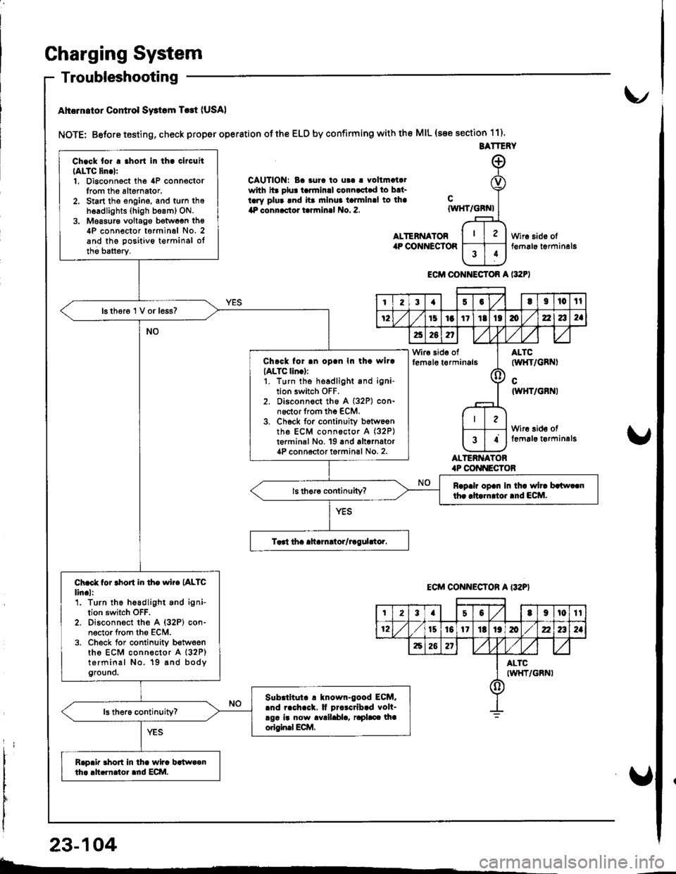
Ahcrn.tor Control Swtom T.rt (USA)
NOTE: Betore testing, check proper operation of the ELD by confirming with the MIL (s€e section 11).
CAUTION: Ba 3urc to ut! | vollmatalwith hr plu! tarmlnal connactad to bat-tary plua and ita mlnua talmlnal to lha4P connactor tarrninal No. 2.
ALTENNATORilP COiINECTOR
cIWHT/GBN}
ALTERNATOR.P CONI{ECTOB
Wire sido olt€m6le t€rminal6
ECM CONI{ECTOR A l:t2F)
BATTERY
Ch.ck tor . .hort In th. clrcuit(ALTC ltn.lr1. Disconnect the 4P connoctorIrom th6 altemator.2. Start tho engine, and turn thoh6adlights (high beam) ON.3. Moasur€ voltago botwoen th64P conn€ctor t6rminal No. 2and the positivo t€rminsl oltho batterv.
16 thor6 1 V or less?
Chrck for .n oD.n In th. wllrIALTC lln.):1. turn the headlight and igni-tion switch OFF.2. Disconnect th6 A (32P) con-noctor from the ECM.3. Ch6ck for continuity b6tw6entho ECM connoctor A (32P)
t€rminal No, 19 and alternator4P connoctor torminal No. 2.
Rrp.h op.n In th. wh. brlw..nth. rltarn oi.nd ECM.
Ch.ct for rhort in th. wire (ALTC
lin.l:'1. Turn the headlight and ignition switch OFF.2. Disconn€ct the A {32P} con-n6ctor from tho ECM.3. Check for conlinuity b€twoenths ECM connector A (32P)
terminal No. 19 8nd bodyground.
Slbrlltut. ! tnown-good ECM..nd rach.ck. It Drorcrlb.d volt-rgr ir now avalldla, raphce lhaorigin.l Ecilt.
Rap.ir 3hort in lha wira bstwaanth. .h.rnator ard ECI\|.
I23{5GtI|l0tl
72151aItIt136zla2a
a26n,/,V
Wir€ side offem6le t€rminals(l
ALTC(wl{T/GRNI
cIWHT/GBNI
Wire 3id€ offemal6 t€rminelg34
ECM CONNECTON A I32P}
t23a50t9t0tt
12t510l1Itt9mz2a2a
62621
ALTCIWHT/GRNI()
23-104
b-.
Page 1162 of 1680
From previol.rs page
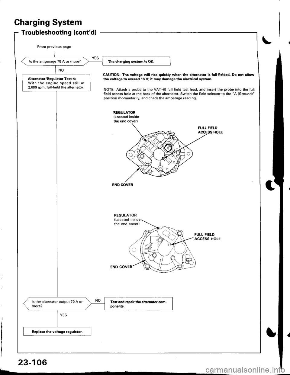
The charging swtem is OK.lsthe amperage 70 A or more?
Alternator/Regulator Test-4:With the engine speed still at2,000 rpm, Iull-Iield the alternator.
Charging System
Troubleshooting (cont'dl
CAUTION: Th6 voltago will rise quickly when the ahernator is ful!fieldcd. Do not .llowth6 voltag€ to €xc6ed 18 V; it may damage tho ol6drical system.
NOTE: Attach a probe to the VAT'40 full field test lead, and insert the probe into the lullfield access hole at the back of the alternator. Switch the field selector to the "A {Ground}"position momentarily, and check the amperage reading.
REGULATOB(Located inside
FULL FIELOACCESS HOLE
END COVEB
END COVER
FULL FIELDACCESS HOLE
L^
23-106
Page 1171 of 1680
)
t
J
Altelnator ttelr Inspecuon ano Aol
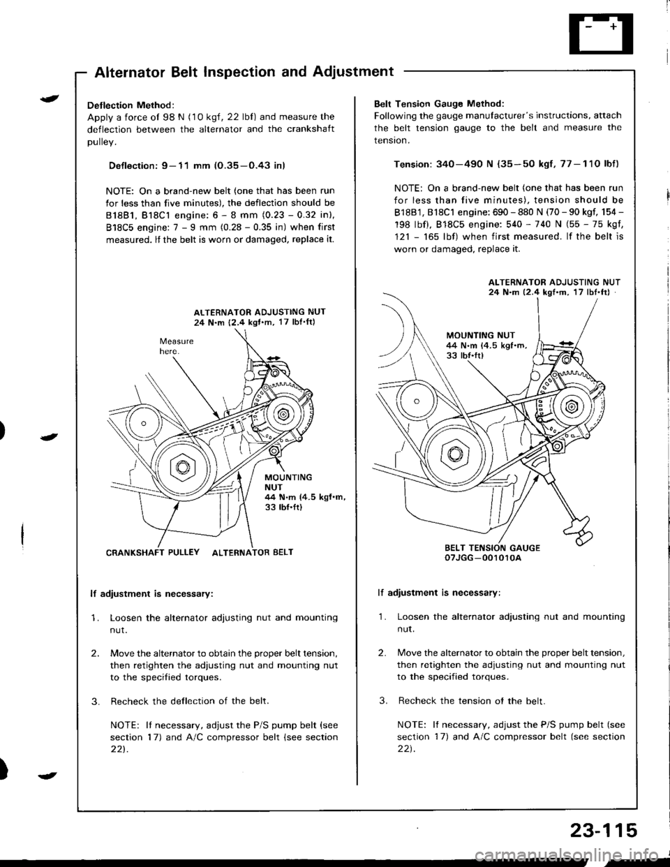
Detlection Method:
Apply a force ol 98 N (1 0 ksl, 22 lbl) and measure the
deflection between the alternator and the crankshaft
DUllev,
Defloction: 9- 11 mm (O.35-O.43 inl
NOTE: On a brand-new belt (one that has been run
for less than five minutes), the deflection should be
81881, Bl8Cl engine: 6 - 8 mm (0.23 - 0.32 inl,
818C5 engine: 7 - I mm (0.28 - 0.35 in) when first
measured, lf the belt is worn or damaged, replace it.
ALTERNATOR ADJUSTING NUT
24 N.m 12,4 kgl.m, 17 lbI'ftl
MOUNTINGNUT44 N.m (4.5 kgf.m,33 tbf.ft)
CRANKSHAFT PULLEY ALTERNATOR BELT
lf adiustment is necessary:
1. Loosen the alternator adjusting nut and mounting
nut.
2.
3.
Move the alternator to obtain the proper belt tension,
then retighten the adiusting nut and mounting nut
to the specified torques.
Recheck the dellection of the belt.
NOTE: lI necessary, adjust the P/S pump belt (see
section 17) and A/C compressor belt (see section
221.
Belt Tension Gauge Method:
Following the gauge manulacturer's instructions, attach
the belt tension gauge to the belt and measure the
tension.
Tension: 340-490 N {35-50 kgf,77-11O lbf)
NOTE: On a brand-new belt (one that has been run
for less than five minutes), tension should be
818B1, 818C1 engine: 690 - 880 N (70 - 90 kgf, 154 -
198 lbf), 818C5 engine: 540 - 740 N (55 - 75 kgf,
121 - 165 lbf) when first measured. lf the belt is
worn or damaged, replace it.
lf adiustment is necessary:
1. Loosen the alternator adjusting nut and mounting
nut.
2.
3.
Move the alternator to obtain the proper belt tension,
then retighten the adjusting nut and mounting nut
to the specified torques.
Recheck the tension ot the belt.
NOTE: It necessary, adjust the P/S pump belt (see
section 17) and A/C compressor belt (see section
22t.
ALTERNATOR ADJUSTING NUT24 N.m 12.4 kgf'm, 17 lbt.ftJ
BELT TENSION GAUGEoTJGG -0010r0A
23-115
J
,-
Page 1175 of 1680
)
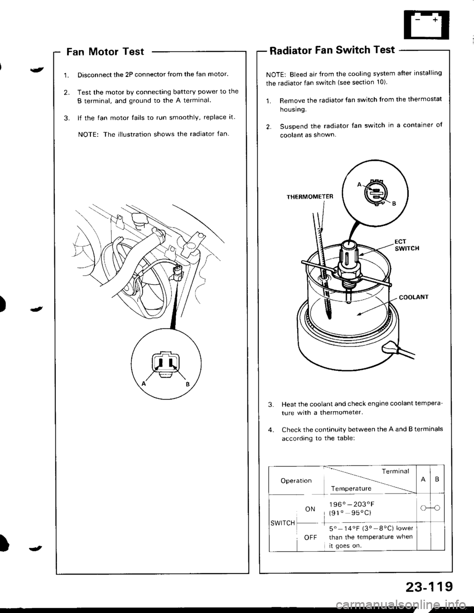
Fan Motor Test
Disconnect the 2P connector from the fan motor.
Test the motor by connecting battery power to the
B terminal, and ground to the A termlnal.
lf the fan motor fails to run smoothly, replace it.
NOTE: The illustration shows the radiator fan.
Radiator Fan Switch Test
NOTE: Bleed air from the cooling system after installing
the radiator fan switch (see section 10)
1. Remove the radiator fan switch from the thermostat
housing.
2. Suspend the radiator fan switch in a container ol
coolanl as shown.
Heat the coolant and check engine coolant tempera
ture with a thermometer.
Check the continuity between the A and B terminals
according to the table:
23-119
Te rm Inal
Operatlon -------\
Tcmoerature ------
ON196. -203'F
(91" 95'C)
-5" 14.F i3" _8"C) ;*,*
than the temperature when
rt goes on.
SWITCH
OFF
B
-o
.-
Page 1184 of 1680
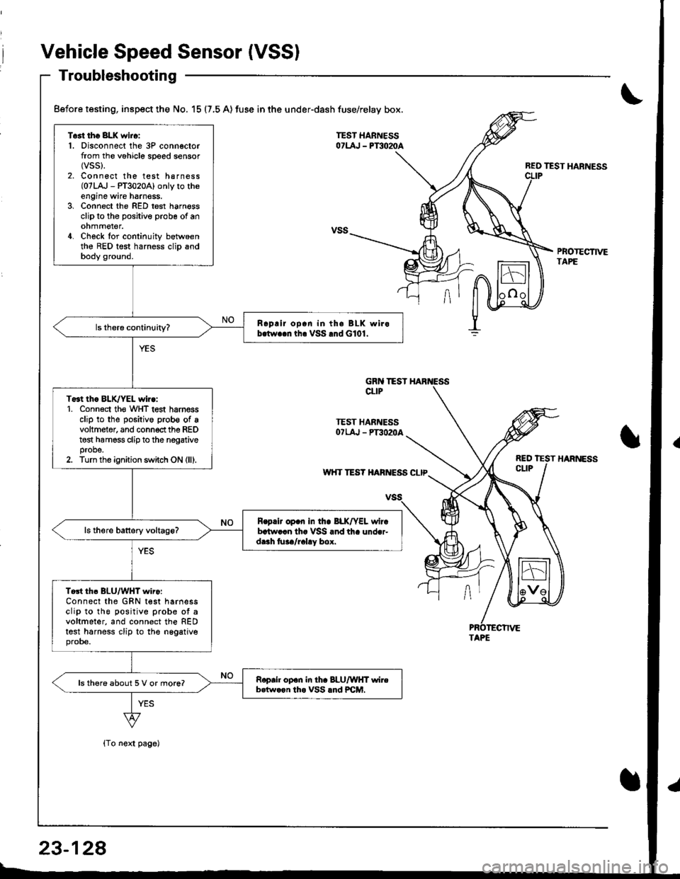
Vehicle Speed Sensor (VSSI
Troubleshooting
{To next page)
REO TEST HARNESS
PBOTECTIVETAPE
Test tho 8LK wiro:1. Disconnect the 3P connectorfrom the vohicle speed sensor(vss).
2. Connect the test harness(07LA,J - PT3020A) only to theengine wire harnoss.3, Connect the RED test harnessclip to the positive probe of anohmmel€r.4. Check for continuity betwoenthe RED test harness clip andbody ground.
Roplir op.n in th. BLK wirob.tw..n tha VSS .nd G101.
To3t thc BLK/YEL wiro:1. Conn6ct th€ WHT test harnessclip to the positive prob€ of avoltmeter, and connect the REDt€st harness clip to the nogativeprobe.2. Turn the ignition switch ON (lll.
R.p.lr op.n In tho BLK/YEL wirebrtw..n th. VSS and th. under-dr.h tu../r.l!y box.
Tort th. BLU/WHT wiro:Connect the GRN test harnessclip to the positive prob€ ot avoltmeter, and connect the REDtest harness clip to the nggatjveprobe.
Roprh op.n in th. 8LU/WHT wireb.tw.on tho VSS lnd PCM.ls there about 5 V or more?
Before testing, inspect the No. 15 (7,5 A) fuse in the under-dash fuse/relay box.
GRN TESTCLIP
TEST HARNESSOTLAJ - PT3O2OA
w'{T TES? HARIVESS CLIP
TAPE
23-128