relay ACURA INTEGRA 1998 Service Repair Manual
[x] Cancel search | Manufacturer: ACURA, Model Year: 1998, Model line: INTEGRA, Model: ACURA INTEGRA 1998Pages: 1680, PDF Size: 53.14 MB
Page 1299 of 1680
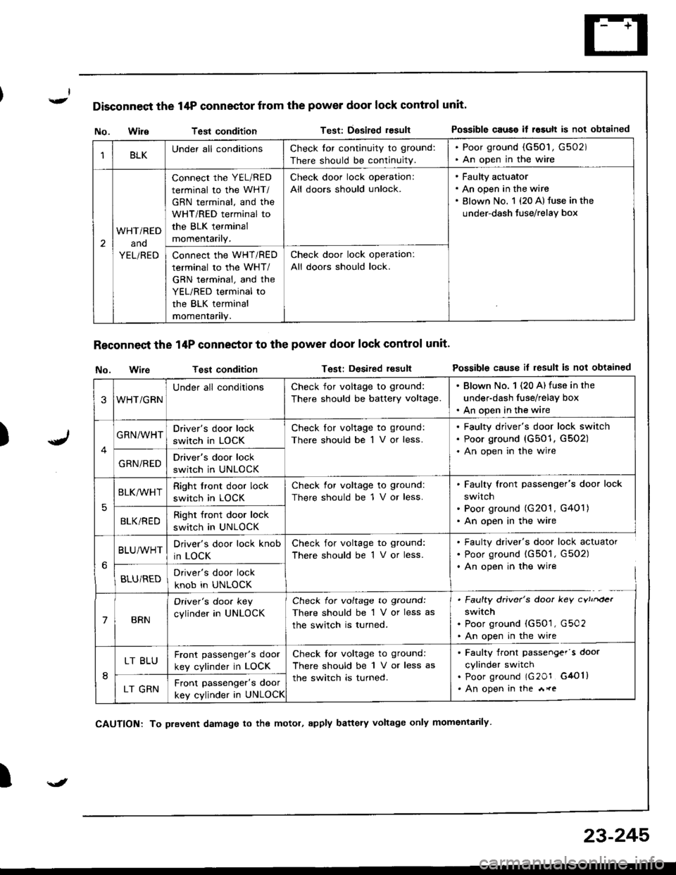
Disconnect the 14P connector from the power door lock control unit'
)
No. WileTest conditionTest: Dgsired resultPossible causo if rosult is not obtained
Reconnect the 14P conneetor to the power door lock control unit'
No. wireTest conditionTest: Desired resultPossible cause il result is not obtained
I
1BLKUnder all conditionsCheck tor continuity to ground:
There should be continuity.
. Poor ground (G50'1, G502). An open in the wire
2
WHTi RED
ano
YEL/RED
connect the YEL/RED
terminal to the WHT/
GBN terminal, and the
WHT/RED terminal to
the BLK terminal
momentarily.
Check door lock operation:
All doors should unlock.
Faulty actuator
An open in the wire
Blown No. 1 {20 A} fuse in the
under-dash Juse/relay box
Connect the WHT/RED
terminal to the WHT/
GRN terminal, and the
YEL/RED terminal to
the BLK terminal
momentanly.
Check door lock operation:
All doors should lock.
3WHT/GRN
Under all conditionsCheck for voltage to ground:
There should be battery voltage.
. Blown No. 1 (20 A) fuse in the
under-dash fuse/relay box. An open in the wire
GRN/WHTDriver's door lock
switch in LOCK
Check lor voltage to ground:
There should be 1 V or less.
Faulty driver's door lock switch
Poor ground (G501, G502)
An open in the wire
GRN/REDDriver's door lock
switch in UNLOCK
5
BLK/WHTRight front door lock
switch in LOCK
Check for voltage to ground:
There should be 1 V or less.
Faulty front passenger's door lock
switch
Poor ground (G201 , G401)
An open in the wireBLKi REDRight front door lock
switch in UNLOCK
BLU/WHTDriver's door lock knob
in LOCK
Check for voltage to ground:
There should be 1 V or less.
. Faulty driver's door lock actuator. Poor ground (G501, G502). An open in the wire
BLU/REDDriver's door lock
knob in UNLOCK
7BRN
Oriver's doo. key
cylinder in UNLOCK
Check for voltage to ground:
There should be 1 V or less as
the switch is turned.
. Faulty driver's door key cvtrrder
switch. Poor ground (G501, G502. An open in the wire
8
LT BLUFront passenger's door
key cylinder in LOCK
Check for voltage to ground:
There should be 1 V or less as
the switch is turned.
. Faulty front passengef's door
cylinder switch. poor ground lG20r G4Ol). An open in the *reLT GRNFront passenger's door
key cylinder in UNLOCK
\J
CAUTION: To prevent damage to the motol, apply battery voltage only momentarily
23-245
Page 1305 of 1680
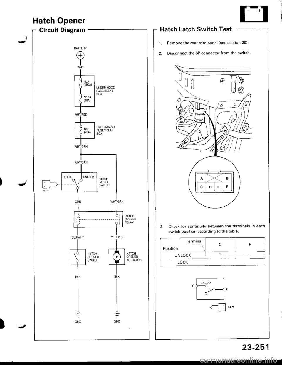
Hatch Opener
Circuit DiagramHatch Latch Switch Test
Remove the rear trim panel lsee section 20).
Disconnect the 6P connector from the switch.
3. Check for continuity between the terminals in each
switch position according to the table.
HATCHOPENEHRELAY
HATCHOPENERACTUATOB
UNDER-HOODFUSE/RELAYBOX
UNDER.DASHFUSE/RELAYBOX
la :llf q ^ll
ELUMHT YEURED
tl
[S-l*0,., f/tl| IoPENEF lt.l I
I ? l'*n'" +_i
tl8LK BLK
tl
tl
tt.:
G503 G503
BATTEFY
(+)
Y
I
-r--t
I I lm,1
uI| )Nov II f. (4oA) |rT '
IWHT/RED
I-r----| )ur II L (2oA) I
IWHTiGRN
fi--l->t_:___J-KEY
Terminal
:- ..- crosrUon-1UNLOCK
LOCK
F
23-251
-----t1< IKEY--,_)
J
Page 1309 of 1680
![ACURA INTEGRA 1998 Service Repair Manual Circuit Diagram
J
WNT/BLK +WHT
BLKYEL YEL/8LU
CABLEREEL
SET/BESUME1 SW]TCH
J
IGNITONCONTROLMODULE(cM)
LT
B lA
i,"YlDGBY
c
IT GRN/RED LTGRN/BLK
BLK
I
:
:2013401
III
I
VEHICLE SPEEDSENSOR (VSS)
M/T: CL ACURA INTEGRA 1998 Service Repair Manual Circuit Diagram
J
WNT/BLK +WHT
BLKYEL YEL/8LU
CABLEREEL
SET/BESUME1 SW]TCH
J
IGNITONCONTROLMODULE(cM)
LT
B lA
i,"YlDGBY
c
IT GRN/RED LTGRN/BLK
BLK
I
:
:2013401
III
I
VEHICLE SPEEDSENSOR (VSS)
M/T: CL](/img/32/56983/w960_56983-1308.png)
Circuit Diagram
J
WNT/BLK +WHT
BLKYEL YEL/8LU
CABLEREEL
SET/BESUME1 SW]TCH
J
IGNITONCONTROLMODULE(cM)
LT
B lA
i,"'YlDGBY
c
IT GRN/RED LTGRN/BLK
BLK
I
:
:2013401
III
I
VEHICLE SPEEDSENSOR (VSS)
M/T: CLLTCH SWITCH \A/T:A,TGEARPostT oN swrc!(oN E].tr tr
8LK 8LK
lltl-0-_L-- --
G301 G2AlG401
UNDER-HOOD FUSEiFELAY BOXUNDEF DASH FUSEi RELAY BOX
lNDICATORL]GHT(0.91W)
BLU/RED
23-255
:?:'
ACC : ACCELERATIONOEC iDECELERATION
Page 1310 of 1680
t
t;
i'l
I
dil
Gruise Gontrol
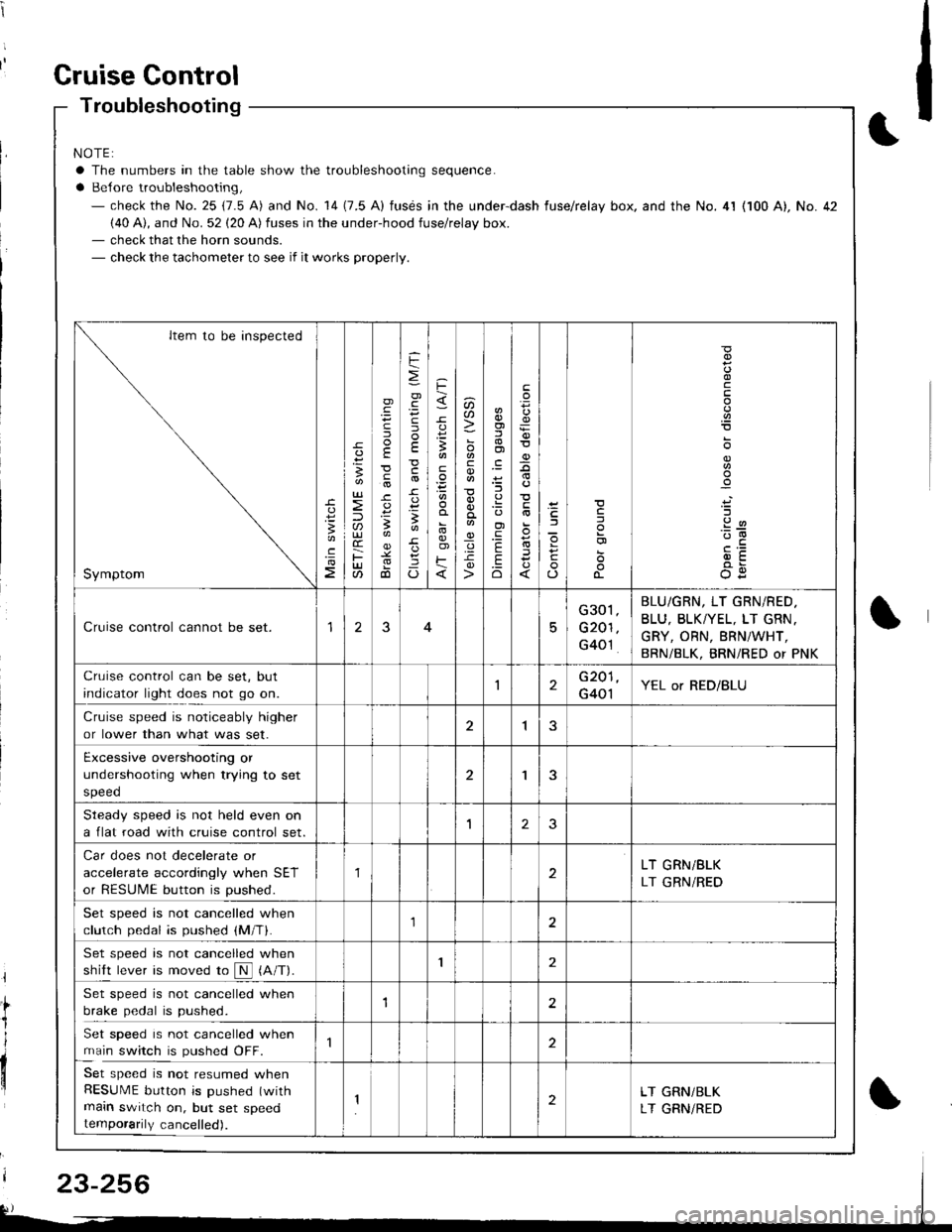
Troubleshooting
NOTE:
a The numbers in the table show the troubleshooting sequence.
a Belore troubleshooting,- check the No. 25 (7.5 A) and No. 14 (7.5 A) fusds in the under-dash fuse/relay box. and the No. 4l (100 A), No. 42(40 A), and No. 52 (20 A) fuses in the under-hood fuse/relay box.- check that the horn sounds.- check the tachometer to see if it works properly.
Item to be inspected
Symptom
c
:3
UJ
lU)(r
F(t
)
E
c
.
F
=
.g
E
-c
!-
Io
F
3
E
o)F
u)U'
co
_q.9-c
o)f,
ol
;l
E
.Eo
F
E
_9
)a
o
o-
o
c
.2
'::-c
OE
Cruise control cannot be set.15
G301
G201
G40't
BLU/GRN, LT GRN/RED.
BLU, BLKTYEL, LT GRN.
GRY, ORN, BRNiWHT,
BRN/BLK, BRNi RED or PNK
Cruise control can be set, but
indicator light does not go on.1G201
G401YEL or RED/BLU
Cruise speed is noticeably higher
or lower than what was set.1
Excessive overshooting or
undershooting when trying to set
speed
'I
Steadv soeed is not held even on
a flat road with cruise control set.1J
Car does not decelerate or
accelerate accordingly when SET
or RESUME button is pushed.
1LT GRN/BLK
LT GRN/RED
Set speed is not cancelled when
clutch pedal is pushed (M/T).1
Set speed is not cancelled when
shift lever is moved ro N (A/T).I
Set speed is not cancelled when
brake pedal is pushed.12
Set speed is not cancelled when
main switch is pushed OFF.
Set speed is not resumed whenRESUME button is pushed (with
main switch on, but set speedtemporarily cancelled).
2LT GRN/BLK
LT GRNiRED
23-256
Page 1312 of 1680
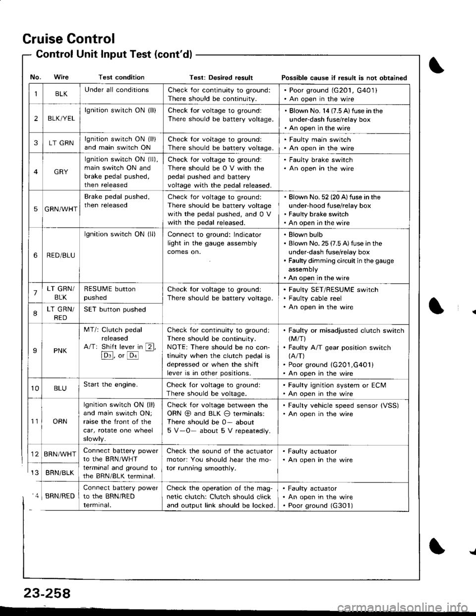
Cruise Control
- Control Unit InputTest(cont'dl
IBLKUnder all conditionsCheck for continuity to ground:
There should be continuity.
. Poor ground (G20l, G401). An open in the wire
2BLK/YEL
lgnition switch ON {ll}Check for voltage to ground:
There should be battery voltage.
. Blown No. l4 (7.5 Alfuse in the
under-dash fuse/relay box. An open in the wire
3LT GRNlgnition switch ON (ll)
and main switch ON
Check for voltage to ground:
There should be battery voltage.
. Faulty main swjtch. An open in the wire
GRY
lgnition switch ON (ll),
main switch ON and
brake pedal pushed,
then released
Check for voltage to ground:
There should be O V with the
pedal pushed and battery
voltage with the pedal released.
. Faulty brake switch. An open in the wire
5GRN/WHT
Brake pedal pushed,
then released
Check for voltage to ground:
There should be battery voltage
with the pedal pushed, and 0 V
with the pedal released.
Blown No. 52 (20 A)fuse in the
under-hood fuse/relay box
Faulty brake switch
An open in the wire
6RED/BLU
lgnition switch ON (ll)Connect to ground: lndicator
light in the gauge assembly
comes on.
Blown bulb
Blown No. 25 (7.5 A)fuse in the
under-dash fuse/relay box
Faulty dimming circuit in the gauge
assembly
An open in the wire
7LT GRN/
BLK
RESUME button
pushed
Check tor voltage to ground:
There should be battery voltage.
Faulty SET/RESUME switch
Faulty cable reel
An open in the wire8LT GRN/
RED
SET button pushed
IPNK
MT/: Clutch pedal
released
A/Tr Shift lever in [2l,
[Dl]. o, [o'l
-
Check for continuity to ground:
There should be continuity.
NOTE: There should be no con-
tinuity when the clutch pedal is
depressed or when the shift
lever is in other positions.
Faulty or misadjusted clutch switch(M/T)
Faulty A/T gear position switch(A/T)
Poor ground (G201,G401)
An open in the wire
't0BLUStart the engine.Check lor voltage to ground:
There should be voltage.
. Faulty ignition system or ECM. An open in the wire
't1ORN
lgnition switch ON (ll)
and main switch ON;
raase the front of the
car, rotate one wheel
slowly.
Check for voltage between the
ORN @ and BLK O terminals:
There should be 0- about
5 V-O- about 5 V repeatedly.
. Faulty vehicle speed sensor {VSS). An open in the wire
BRN/WHTConnect battery power
to the BRN/WHT
terminal and ground to
the BRN/BLK terminal.
Check the sound of the actuator
motor: You should hear the mo-
tor running smoothly.
. Faulty actuator. An open in the wire
BRNi BLK
Connect battery power
to the BRN/RED
Iermrnal.
Check the operation of the mag-
netic clutch: Clutch should click
and output link should be locked.
Faulty actuator
An open in the wire
Poor ground (G30'l)
No. Wire Test conditionTest: Desiled result Possible cause il lesult is not obtained
' 4 I BRN/RED
{
{
23-258
-L
Page 1319 of 1680
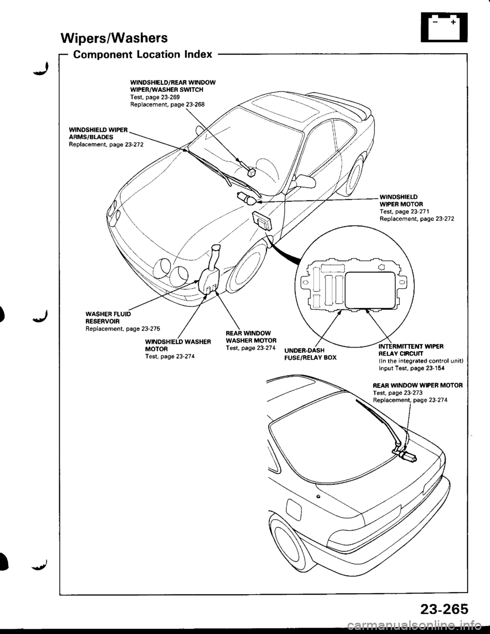
)
Wipers/Washers
Component Locationlndex
WINDSHIELD/BEAR WINDOWWIPER/WASHER SWITCHTest, page 23-269Replacement. page 23-268
wlNOSHIELD WIPERARMS/BLADESReplac6ment, page23-272
WINDSHIELDWIPER MOTORTest, page 23 271Replacement. page 23-272
WINDSHIELD WASHERMOTORfest. page 23-27 4
REAR WINDOWWASHER MOTORTest, page 23-2"14UNDER.DASHFUSE/RELAY BOX
INTERMTNEMT WIPERFELAY CIRCUN(ln the integrated control unit)Inpur Test, page 23-154
I
ul!
REAR WINDOW WIPER MOTORTest, page 23-273
23-265
Page 1320 of 1680
![ACURA INTEGRA 1998 Service Repair Manual (
Wipers/Washers
Circuit Diagram
UNDEF.OASHFUSEiRELAYSOX
NTE NMI]TEIIIWPES RELAYCIFCUIT/ In lhe inr6grar6d \ @nlrolun( I
IGNITIONSW TCHUNDER,HOOD FUSE/RELAY BOX
GRI]/BLK
GFIVBLK
WINDSHIELO WPENJWASHE ACURA INTEGRA 1998 Service Repair Manual (
Wipers/Washers
Circuit Diagram
UNDEF.OASHFUSEiRELAYSOX
NTE NMI]TEIIIWPES RELAYCIFCUIT/ In lhe inr6grar6d \ @nlrolun( I
IGNITIONSW TCHUNDER,HOOD FUSE/RELAY BOX
GRI]/BLK
GFIVBLK
WINDSHIELO WPENJWASHE](/img/32/56983/w960_56983-1319.png)
(
Wipers/Washers
Circuit Diagram
UNDEF.OASHFUSEiRELAYSOX
NTE NMI]TEI'IIWPES RELAYCIFCUIT/ In lhe inr6grar6d \ @nlrolun( I
IGNITIONSW TCHUNDER,HOOD FUSE/RELAY BOX
GRI]/BLK
GFIVBLK
WINDSHIELO WPENJWASHER SWITCH
BLK
G201G401
* : Wilh combined washer-wiDer ooeralion
BLI(GRN
I
A w'',,os"( M ) WASHER
Y
MoroF
8LK
I
G301
23-266
I
Page 1331 of 1680

!
Gomponent/Wiring Locations Index
SRS INDICATOR LIGHT(ln the gauge assembly)Troubleshooting, page 23-287Gauge assembly, page 23-126
To HORN SWITCH
CABLE REELReplacement,page 23-322
DRIVER'S AIRBAGReplacement. page 23-317Disposal, page 23-320To DRIVER'S AIRBAG
DASHBOARD WIRE HARNESSFRONT PASSENGER'SAIRBAGBeplacement, page 23-317Disposal, page 23-320
to SRS INDICATOR LIGHT in GAUGE ASSEMBLY5P CONNECTOR
SRS MAIN HARNESSTo MAINWIRE HARNESS3P CONNECTOR
SRS MAINHARNESSto UNDER-DASHFUSE/RELAYBOX2P CONNECTOR
HARNESSto FRONT PASSENGERS AIRBAG2P CONNECTOR
SRS MAIN
SERVICE CHECXCONNECTOR {2PIIBRNAAIHT, BLK]to CABLE REEL2P CONNECTOR
MAIN WIRE HARNESSto DASHBOARD WIREHARNESS16P CONNECTOR
ERASE SIGNAL (MES}SRS UNITGBOUNOSRS MAIN HARNESSSRS UNIT(lncluding safing sensorano rmpact sensor)R6placement, page 23-326
2P CONNECTORSRS MAIN HARNESSto SRS UNIT18P CONNECTOR
S\--0
[GRN, GRNI or IWHT, BLKI
23-27A
Page 1332 of 1680

Description
I
J)
)
'\' '\, ili \.-.-1 i^\\,,; i \
The SRS is a safetv device which, when used in coniunction with the seat belt, is designed to help protect the driver and
front passenger in a frontal impact exceeding a cenain set limit. The system consists ot the SRS unit (including safing sen-
sor and imDact sensor), the cable reel, the driver's airbag, and front passenger's airbag
Operation t'Its
The main circuit in the SRS unit senses and judges the force ot impact and, il necessary, ignites the inflator charges. If bat-
tery voltage is too low or power is disconnected due to the impact, the back-up power circuii will keep voltage at a con-
stant level.
For the SRS to operate:
(1) The impact sensor and safing sensor must activate and send electric signals to lhe mictop.Goi
{2) The microprocessor must compute the signals and send signals to the airbag inflators'
(3) The inflators must ignite and deploy the airbags sE Lr.r
UNDER DASHFUSE/RELAYBOX
Dnftr sAtacranroq
IIMPACT I ] )
F80t{TPASSEI{GEffSAIRSAGINFLAIOR
Drc MES SCS rDC
Self-diagnosis System
A self-diagnosis circuit is built into the sRs unit; when the ignition switch is turned oN (ll), the sRS indicator light comes
on and goes off after about six seconds if the system is operating normally'
lf the light does not come on, or does not go off after six seconds, or if it comes on while driving. it indicates an abnormal-
ity in the system. The system must be inspected and repaired as soon as possible'
For better servicesbility. the memory will store the cause of the malfunction, and the data link circuit passes on the infor-
mation from the memory to the data link connector (DLC). This information can be read with the Honda PGM Tester con-
nected to the DLc (16P).
23-279
J
Page 1333 of 1680

Circuit Diagram
FRONTPASSENGEF'SAJRBAGINFLATOR
f\4r
tlGRN GRN(YEL) (BLi.,'YEL)
I
G701
IGNITIONswtTcH
SRS INOICATOF CIBCUIT(ln the gauge assembly)
8LU
I
I
siEi'
IGRN
GRN(8RN)
I?
RNAVHT BRII/WHTlltl\---7 \*7
ECM SERVICECHECKcoirNEcTon
WHT/BLK +WHT
t"'
DATA LINKCONNECTOF(DLC)(r6P)
UNDEF-DASHFUSURELAY80x
ELKRED
J
PGM-FImain r€lay
MEIiIORY ERASEr2pt SIGNAL (MESIcoNNECToR (2P)
SRS UNIT TERMJNALS
BLX
G201G401
-NOER.NOOD FUSE/RELAY BOX
SRS INDICATORLIGHT 0.4W)
10 14 1 13 6 7(VA) 3(VB)SRS UNIT16 17 15 9188
DRIVER'SAJFBAGINFLATOR
1367I
10,/1,/1314151718
lerminal sde o{ male tefinnals
23-280
\'