value ACURA INTEGRA 1998 Service User Guide
[x] Cancel search | Manufacturer: ACURA, Model Year: 1998, Model line: INTEGRA, Model: ACURA INTEGRA 1998Pages: 1680, PDF Size: 53.14 MB
Page 525 of 1680
L
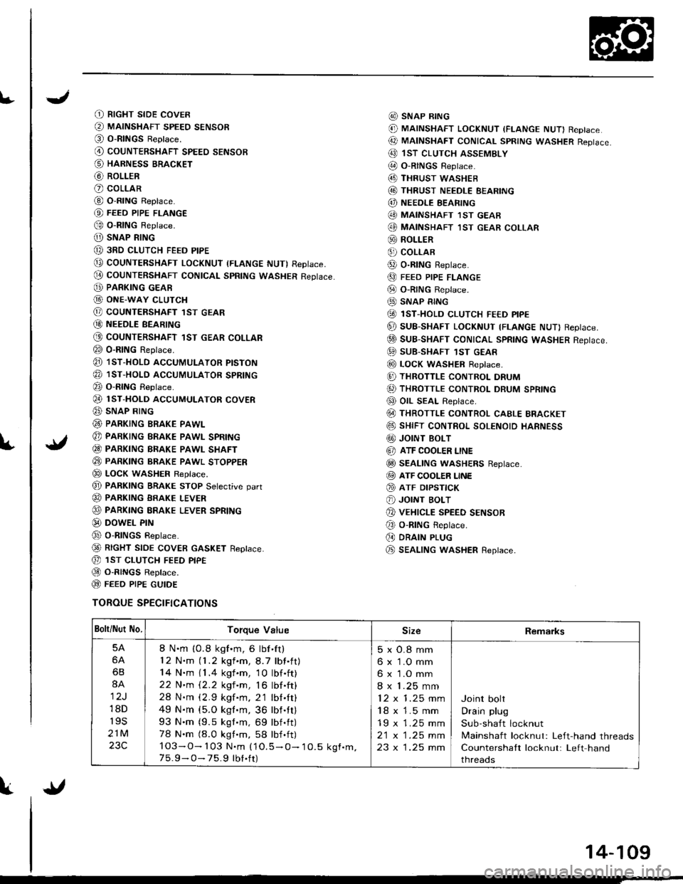
(t RtcHT sroE covER
@ MAINSHAFT sPEEo sENsoR(O O-RINGS Reptace.
@ couNTERSHAFT spEEo sENsoR
@ HARNESS BRACKET
@ RoLLER
O coLLAR
@ O-RING Replace.
@ FEEo PIPE FLANGE
@ o-RtNG Reptace.
O) SNAP RING
@ 3RD cLUTcH FEED PIPE
@ COUNTERSHAFT LocKNUT (FLANGE NUT) RepIace,
@ couNTERSHAFT CONtcAL spRtNG wAsHER Reptace.
@ PARKING GEAR
G) ONE-WAY cLUTcH
@ COUNTERSHAFT lST GEAR
@ NEEoLE BEARTNG
@ COUNTERSHAFT 1ST GEAR COLLAR
€0 o-RING Reprace.
@ 1sT-HoLD AccUMULAToR ptsTok
@ 1sr-HoLD AccUMULAToR spRtNG
@ o-RING Reptace.
@ rsr-HoLD AccUMULAToR covER
@ SNAP RING
@ PARKING BRAKE PAWL
@ PARKING BRAKE PAWL SPRING
€0 PARKTNG BRAKE PAWL SHAFT
@ PARKTNG BRAKE pawl sroppER
€0 LOCK WASHEF Replace.
@ PARKTNG BRAKE STOP Setecrive oart
@ PARKING BRAKE LEVER
@ PARKING ERAKE LEVER SPRING
@ DowEL PrN
@ o-RlNGs Reptace.
@ RtcHT StOE COVER GASKET Reptace.
@ 1sr cLUTcH FEED ptpE
@ O-R|NGS Reptace.
@ FEEO P|PE GUTOE
TOROUE SPECIFICATIONS
@ SNAP R|NG
@ MAINSHAFT LocKNUT (FLANGE NUT) Replace
@ MAtNSHAFT coNtcAL spRtNG wAsHER Reptace.
@ 1sT clurcH ASSEMBLY
@ O-RINGS Reptace.(4D THRUST wASHEB
@ THRUST NEEDLE EEARING
@) NEEDLE EEARING
@ MAINSHAFT 1sT GEAB
@ MAINSHAFT ,IsT GEAR coLLAR
@ ROLLER
€) coLLAR
@ o-R|NG Reptace.
@ FEED PIPE FLANGE
@ o-RtNG Reptace.
@ SNAP RING
@ 1sT-HoLD cLUTcH FE€D ptpE
@ SUB-SHAFT LOCKNUT TFLANGE NUT) Reptace.
@ suB-SHAFT CONTCAL SpRtNG WASHER Reptace.
@ SUB-SHAFT 1sT GEAR
@ LocK WASHER Reptace.
@ THRoTTLE coNTRoL DRUM
6, THRoTTLE coNTRoL DRUM SPRING
@ OIL SEAL Replace.
@ THRoTTLE coNTRoL cAELE BRAGKET
@ sHtFT coNTRoL soLENoto HARNESS
G0) JOINT BOLT
@ ATF COOLER LINE
@ SEAL|NG wASHERS Reptace.
@ ATF cooLER LINE
@ ATF DrPsflcK
@ JOINT BoLT
@ vEHrcLE SPEED sENsoR
@ o-RING Reptace.
(, DRAIN PLUG
@ SEAL|NG wasHER Replace.
Bolti Nut No.Torque ValueSizeRemarks
5A
6A
6B
8A
12J
18D
r9s
21M
23C
8 N.m (0.8 kgf.m, 6 lbf'ft)
12 N.m (1.2 kgf.m,8.7 lbf.ft)
14 N.m { 1 .4 kgf .m, 1 0 lbf .ft)
22 N'm 12.2 kgf 'm, 16 lbf .ft)
28 N.m (2.9 kgf.m. 2'1 lbl.It)
49 N.m {5.O kgl.m, 36 lbf.tt)
93 N.m (9.5 kgt.m, 69 lbf.tt)
78 N.m (8.0 kgt.m, 58 lbf .ft)
103-O- 103 N.m (1O.5 - O- 10.5 kgf.m.7 5.9 - O- 75.9 tbt.ft)
5xO.8mm
6 x 1.O mm
6 x 1.O mm
8 x 1.25 mm
12x1.25mm
18 x 1.5 mm
19 x 1.25 mm
2t x |.25 mm
23 x 1.25 mm
Joint bolt
Drain plug
Sub-shaft locknut
Mainshaft locknut: Left-hand threads
Countershaft locknut: Left hand
threads
{l
14-109
Page 527 of 1680
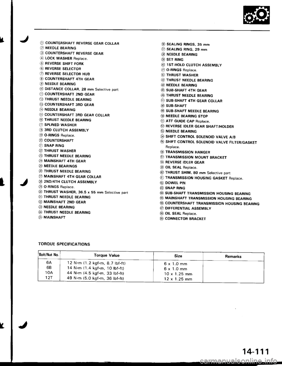
fO) COUNTERSHAFT REVERSE GEAR COLLAR(, NEEDLE BEARING
@ couNTERSHAFT REVEBsE GEAR(4 LOCK waSHER Replace.
G) REVERSE sHtFr FoRK
G) REVERSE SELECTOR
O REVERSE SELEcToR HUB
@ coUNTERSHAFT 4TH GEAR
O NEEDLE BEARING
tE DISTANCE COLLAR, 28 mm Setective part(} COUNTERSHAFT 2ND GEAR
[, THBUST NEEDLE BEARING
@ coUNTERSHAFT 3RD GEAR
[E NEEDI.E BEARING(' COUNTERSHAFT 3RD GEAR COLLAR
@ THRUST NEEDLE BEARING(, SPLINED WASHER
@ 3RD cLUTcH ASSEMBLY
t0 O-RINGS Replace.
@ couNTERSHAFT(?]) SNAP RING
@ THRUST WASHER
@ THRUST NEEDLE BEARING
Q} MAINSHAFT 4TH GEAR
@ NEEDLE BEARINGS
@ THRUST NEEDLE BEARING
@ MAINSHAFT 4TH GEAR coLLAR
€O 2ND/4TH cLUTcH ASSEMBLY
@ O-RINGS Reptace.
@ THRUST WASHER.36.S x 55 mm Setective part
C]) THRUST NEEoLE BEARING
@ MAINSHAFT 2ND GEAR
@ NEEDLE BEARING
0t THRUST NEEDLE BEARTNG
@ MAINSHAFT
@ SEALTNG RtNGs, 35 mm
€D SEAL|NG R|NG. 29 mm
@ NEEDLE B€ARING
@ sET RING
@ lsT.HoLD cLUTCH ASSEMBLY
@ o-RtNGs Reptace.
(, THRUST WASHER
@ THRUST NEEDLE BEARING
@ NEEDLE BEARING
@ SUB-SHAFT 4TH GEAR(O THRUST NEEDLE BEARING
@ sUB-SHAFT 4TH GEAR coLLAR
@ SUB-SHAFT
@ SUB-SHAFT NEEDLE EEARING
@ NEEDLE BEARTNG sToP
@ ATF GUTDE cAp Reptace.
@ REVERSE IDLER GEAR sHAFT/HoLDER
@ NEEDLE BEARING
(i) sHrFT coNTRoL soLENotD vALvE A/B
@ sHrFT coNTRoL soLENotD vALVE FTLTER/GASKETReplace.
@ TRANSMISSIoN HANGER
.5, TRANSMISSIoN MoUNT BRACKET
@) REVERSE TDLER GEAR
@ otL SEAL Replace.
@ THRUST SHIM, SO mm Setective part
@ TRANSMTSSTON HOUSTNG GASKET Reptace.
@ DowEL PtN
@ SNAP RING
@ SUB-SHAFT TRANSMlsstoN HoustNG BEARTNG
@ MA|NSHAFT TRANsMtssroN HoustNG BEARTNG
@ CoUNTERSHAFT TRANSMIssloN HoUsING BEARING
@ DIFFERENTIAL ASSEMBLY
@ oll- SEAL Replace.
E9 CONNECTOR BRACKET
TOROUE SPECIFICATIONS
I
Bolt/Nur No.Torque ValueSizeRemarks
6A
6B
10A
12r
'12 N.m {1.2 kgf.m, 8.7 tbf.ft)14 N.m (1.4 kgl.m, 1O tbf.ft)44 N.m {4.5 kgf 'm, 33 tbf .ft}
49 N.m (5.O kgf.m, 36 lbf.tt)
6 x 1.O mm
6 x 1.0 mm
10 x 1.25 mm
12x1.25mm
14-111
Page 529 of 1680
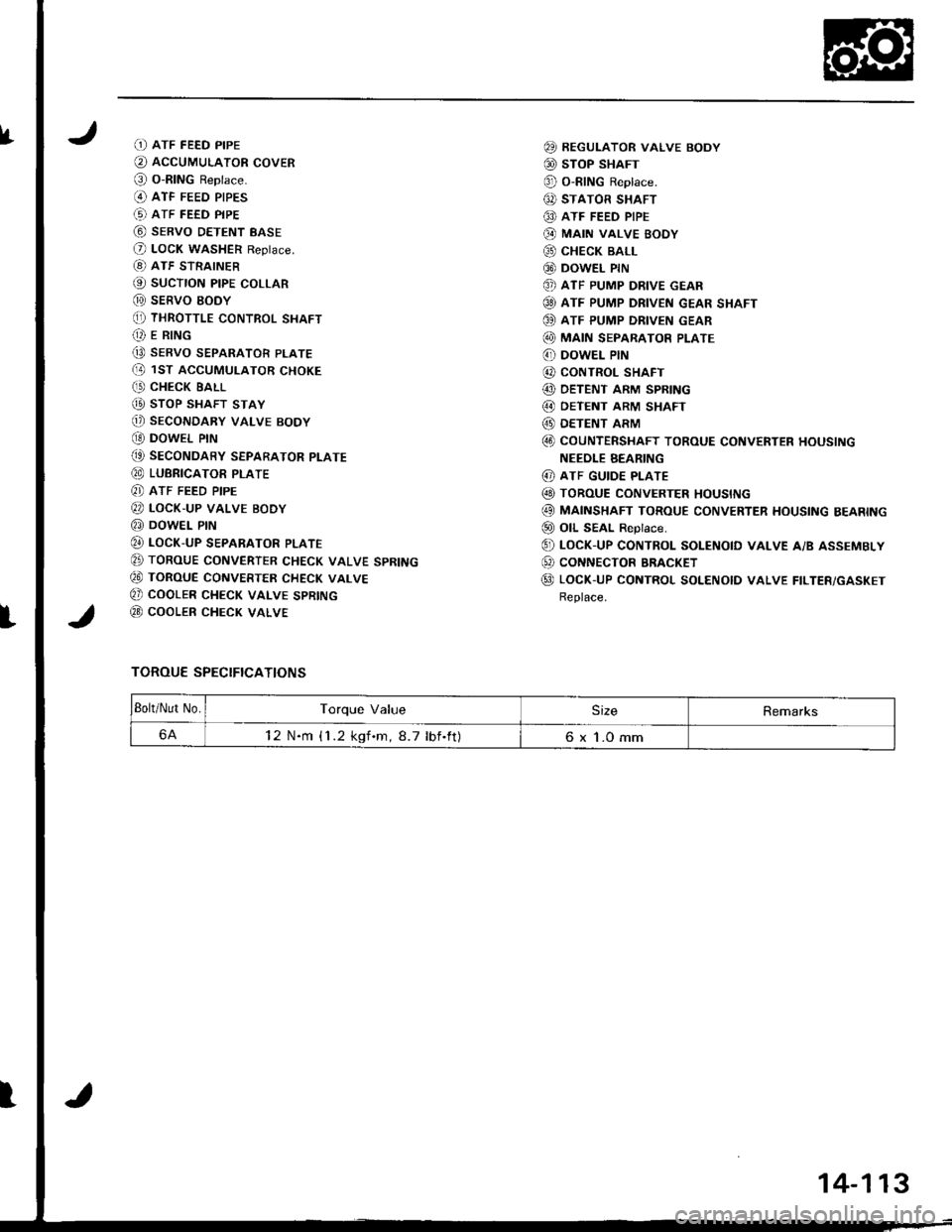
IfD ATF FEED PIPE
O AccUMULAToR covER
@ o-RING Reptace.(O ATF FEED PIPES
(!) ATF FEED PIPE
@ sERvo DETENT BASE
O LocK WASHER Reptace.
[8) ATF STRAINER
@ sucTroN ptpE coLLAR
@ sERVO EODY(, THRoTTLE coNTRoL SHAFT(t E R|NG
Q9 SERVO SEPARATOR PLATE(D 1ST ACCUMULAToR cHoKE
C' CHECK EALL
@ sToP SHAFT STAY
@) SECONDARY VALVE BODY
OO DOWEL PIN
(t SEcoNDARY SEPARAToR PLATE
@ LUBRICAToR PTATE
8] ATF FEED PIPE
@ LocK-uP vALvE BoDy
@ DowEL PrN
@ LocK-uP SEPARAToR PLATE
E TORoUE CoNVERTER cHEcK VALVE SPRING
€0 ToRouE CoNVERTER cHEcK vALvE
Q) COOLER CHECK VALVE SPRING
@ cooLER cHEcK VALVE
TOROUE SPECIFICATIONS
@ REGULAToR vALvE BoDY
@ sToP SHAFT
@ o-RING Reptace.
6, STATOR SHAFT
@ ATF FEED PIPE
@ MA|N VALVE BOOY
@ cHEcK BALL
@ DowEL PrN
@ ATF PUMP DRIVE GEAR
@ ATF PUMP DRIVEN GEAR SHAFT
OO ATF PUMP DRIVEN GEAR
@ MA|N SEPARAToR PLATE
6' DowEL PIN
@ CONTROL SHAFT
@ DETENT ARM SPRING
@ OETENT ARM SHAFT
@ DETENT ARM
@ coUNTERSHAFT ToRoUE coNVERTER HoUSING
NEEOLE BEARING
@ ATF GUIDE PLATE
@ ToRouE coNvERTER HoustNG
@ MAINSHAFT ToRoUE coNvERTER HousING BEARING
@ oll SEAL ReDtace.
@ LocK-up coNTRoL soLENotD vALvE A/B ASSEMBLy
@ coNNEcToR BRACKET
@ LocK-UP coNTRoL SoLENoID vALvE FILTER/GASKET
Replace.
Bolt/Nut No.Torque ValueSizeRemarks
6A12 N.m {1 .2 kgf.m,8.7 lbf.ft)6 x 1.0 mm
I
14-113
Page 613 of 1680
Differential
Ted Roll
(B18C1
er Bearinr
engine)
Preload Adjustment (cont'd)aperelng
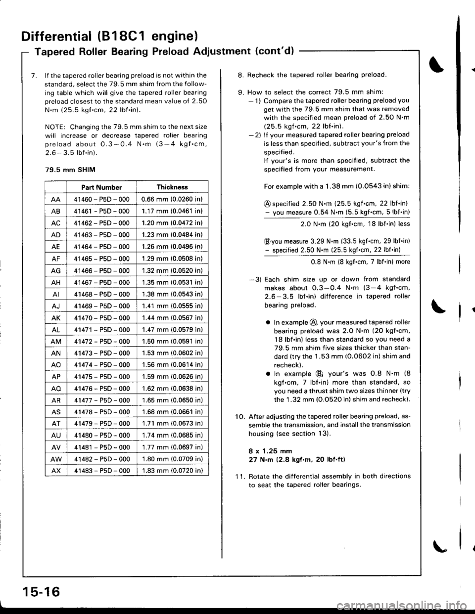
7. lf the tapered roller bearing preload is not within the
standard, select the 79.5 mm shim from the follow-
ing table which will give the tapered roller bearing
preload closest to the standard mean value o{ 2.50
N.m (25.5 kgt.cm, 22 lbf.in).
NOTE: Changing the 79.5 mm shim to the next size
will increase or decrease tapered roller bearing
preload about O.3-0.4 N.m (3-4 kgl.cm,
2.6 - 3.5 lbf.in).
79.5 mm SHIM
Part NumberThickness
41460-PsD-0000.66 mm (0.0260 in)
AB41461 - P5D - 0001.17 mm (0.0461 in)
AC41462-PsD-0001.20 mm (0.0472 in)
AD41463-P5D-0001.23 mm (0.0484 in)
AE41464-PsD-000'1.26 mm (0.0496 in)
AF41465-PsD-0001.29 mm (0.0508 in)
AG41466-PsD-0001.32 mm (0.0520 in)
AH41467-PsD-0001.35 mm 10.0531 in)
AI41468-PsD-0001.38 mm (0.0543 in)
41469-P5D-0001.41 mm (0.0555 inl
AK41470-PsD-0001.44 mm (0.0567 in)
AL41471 - PsD - 000'1.47 mm {0.0579 in}
41472-P5D-0001.50 mm (0.0591 in)
AN41473-PsD-0001.53 mm {0.0602 in}
AO41474-P50-0001.56 mm (0.0614 in)
AP41475-PsD-0001.59 mm (0.0626 in)
AO41476-P5D-000'1.62 mm {0.0638 in}
AR41477-P5D-0001.65 mm (0.0650 in)
41478-P5D-0001.68 mm (0.0661 in)
41479-P50-0001.71 mm (0.0673 in)
AU41480-PsD-0001.74 mm (0.0685 in)
41481 - PsD - 000'1.77 mm (0.0697 in)
41482-PsD-000'1.80 mm (0.0709 in)
AX41483-P5D-0001.83 mm (0.0720 in)
8. Recheck the tapered roller bearing preload.
9. How to select the correct 79.5 mm shim:
1) Compare the tapered roller bearing preload you
get with the 79.5 mm shim that was removed
with the soecified mean Dreload of 2.50 N'm
(25.5 kgf .cm, 22 lbf.in).- 2l ll vour measured tapered roller bearing preload
is less than specified, subtract your's from the
specitied.
lf vour's is more than specitied, subtract the
soecified from vour measurement.
For example with a 1.38 mm {0.0543 in) shim:
@ specified 2.50 N.m (25.5 kgf.cm, 22 lbl.in)- you measure 0.54 N.m (5.5 kg{.cm, 5lbl.in}
2.0 N.m (20 kgf.cm, 18lbf.in) less
@you measure 3.29 N.m (33.5 kgI.cm, 29 lbt.in)- specified 2.50 N.m (25.5 kgf.cm, 22 lbf.in)
0.8 N.m (8 kgf.cm,7lbf.in) more
-3) Each shim size up or down from standard
makes about O.3-0.4 N.nt (3-4 kgf.cm,
2.6-3.5 lbl.in) difterence in tapered roller
bearing preload.
a In example @, your measured tapered roller
bearing preload was 2.O N.m (2O kgt.cm,
18 lbf in) less than standard so you need a
79.5 mm shim live sizes thicker than stan-
dard {try the 1.53 mm (O.0602 in) shim and
recheck).
a ln example @ your's was 0.8 N.m {8
kgf.cm,7lbf.in) more than standard. so
you need a thrust shim two sizes thinner (try
the 1 .32 mm (O.O52O in) shim and recheck).
1O. After adjusting the tapered roller bearing preload, as-
semble the transmission, and installthe lransmission
housing (see section 13).
8 x 1.25 mm
27 N,m (2.8 kgt'm, 20 lbf.ft)
11. Rotate the difterential assembly in both directions
to seat the tapered roller bearings.
1 5-16
\
Page 622 of 1680
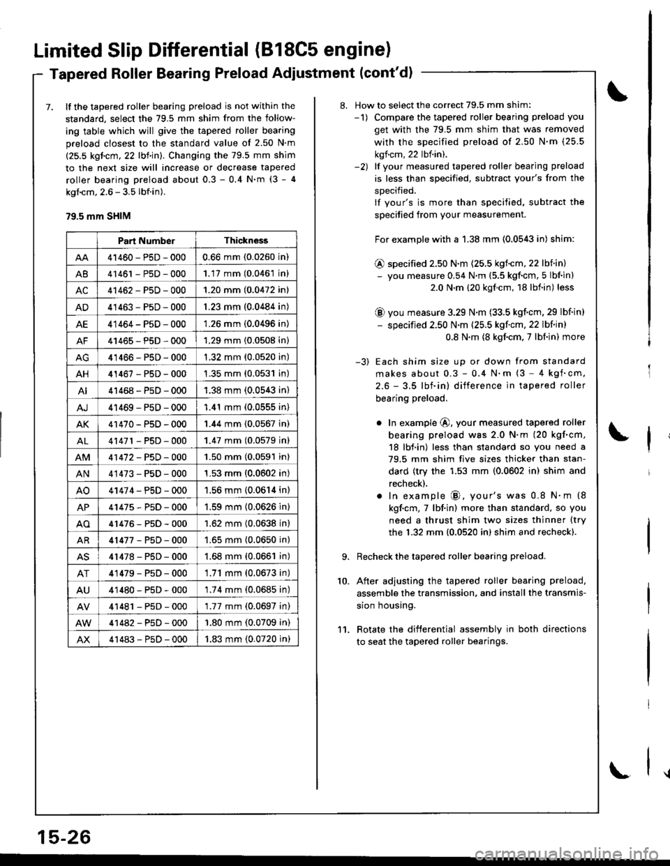
Limited Slip Differential (B18C5 engine)
Tapered Roller Bearing Preload Adiustment (cont'd)
7. lf the tapered roller bearing preload is not within the
standard, select the 79.5 mm shim from the follow-
ing table which will give the tapered roller bearing
preload closest to the standard value of 2.50 N'm
(25.5 kgicm, 22 lbf in). Changing the 79.5 mm shim
to the next size will increase or decrease tapered
roller bearing preload about 0.3 - 0.4 N'm (3 - 4
kgl.cm, 2.6 - 3.5 lbf.in).
79.5 mm SHIM
Part NumberThickness
41460-PsD-0000.66 mm (0.0260 in)
A841461 - P5D - 0001.17 mm (0.0461 in)
AC41462-P5D-0001.20 mm (0.0472 in)
AD41463-P5D-0001.23 mm (0.0484 in)
AE41464-P5D-0001.26 mm (0.0496 in)
AF41465-P5D-0001.29 mm (0.0508 in)
41466-PsD-0001.32 mm (0.0520 in)
AH41467-PsD-0001.35 mm (0.0531 in)
AI41468-P5D-0001.38 mm (0.0543 in)
AJ41469-PsD-0001.41 mm (0.0555 in)
AK41470-PsD-0001.44 mm (0.0567 in)
AL41471 - PsD - 0001.47 mm (0.0579 inl
41472-P5D-0001.50 mm (0.0591 in)
AN41473-P5D-0001.53 mm (0.0602 in)
AO41474-PsD-0001.56 mm (0.0614 in)
AP41475-P5D-0001.59 mm (0.0626 in)
AO41476-P5D-0001.62 mm (0.0638 in)
AR41477-P5D-0001.65 mm (0.0650 in)
AS41478-PsD-0001.68 mm (0.0661 in)
AT41479-P5D-0001.71 mm (0.0673 in)
AU41480-PsD-0001.74 mm (0.0685 in)
41481 - PsD - 0001.77 mm (0.0697 in)
41482-P5D-000'1.80 mm (0.0709 in)
AX41483-P5D-0001.83 mm (0.0720 in)
15-26
\
8. How to select the correct 79,5 mm shim:-1) Compare the tapered roller bearing preload you
get with the 79.5 mm shim that was removed
with the sDecified preload of 2.50 N'm (25.5
kgf.cm, 22 lbf.in).-2) lf vour measured tapered roller bearing preload
is less than specified, subtract your's from the
sDecified.
lf your's is more than specified, subtract the
specified from your measurement.
For example with a 1.38 mm (0.0543 in) shim:
@ specified 2.50 N.m (25.5 kgf.cm,22 lbiin)- you measure 0.54 N.m (5.5 kgf'cm, 5 lbf in)
2.0 N.m (20 kgf.cm, 18 lbf.in) less
@ you measure 3.29 N.m (33.5 kgf.cm, 29 lbf in)
- specified 2.50 N'm (25.5 kgf'cm, 22 lbf in)
0.8 N.m {8 kgf.cm. 7 lbf in) more
-3) Each shim size up or down from standard
makes about 0.3 - 0,4 N.m (3 - 4 kgf'cm,
2.6 - 3.5 lbf.in) difference in tapered roller
bearing preload.
o In example @, your measured tapered roller
bearing preload was 2.0 N.m (20 kgf.cm,
18 lbf.in) less than standard so you need a
79.5 mm shim five sizes thicker than stan-
dard (try the 1.53 mm (0.0602 in) shim and
recheck).
. In example @, your's was 0.8 N.m (8
kgf.cm,7 lbf.in) more than standard, so you
need a thrust shim two sizes thinner (try
the 1.32 mm {0.0520 in) shim and recheck).
Recheck the tapered roller bearing preload.
After adjusting the tapered roller bearing preload,
assemble the transmission, and install the transmis-
sion housing.
Rotate the difterential assembly in both directions
to seat the tapered roller bearings.
10.
11.
Page 656 of 1680
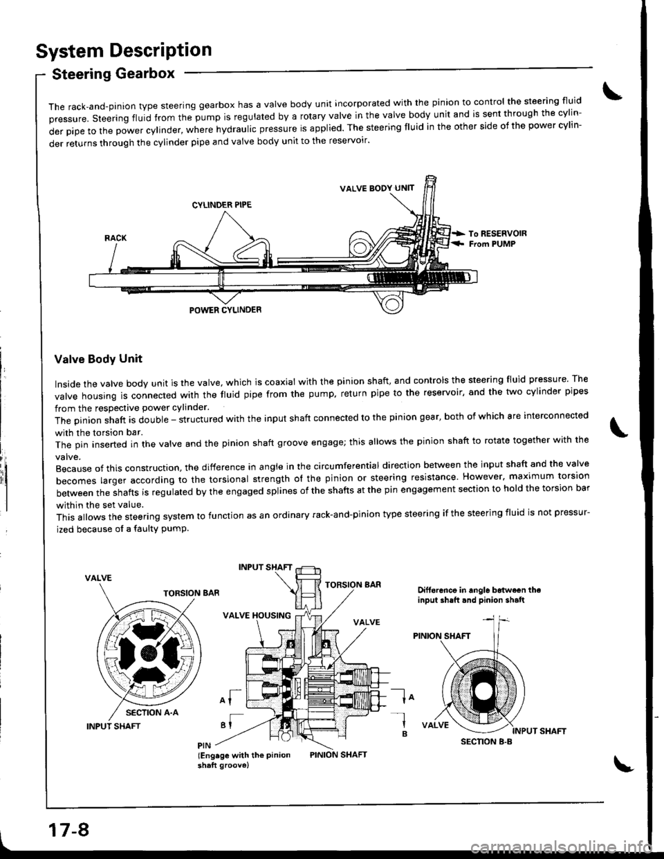
System DescriPtion
Steering Gearbox
it
The rack,and-pinion type steering gearbox has a Valve body unit incorporated with the pinion to control the steering fluid
pressure. steering fluid from the pump is regulated by a rotary valve in the valve body unit and is sent through the cylin-
derpipetothepowercy|inder,wherehydrauIicpressureisapp|ied.Thesteeringf|Uidintheothersideofthepowercy|in-
der returns through the cylinder pipe and valve body unit to the reservoir'
Valve Body Unit
Inside the valve body unit is the valve, which is coaxial with the pinion shaft, and controls the steering fluid pressure The
valve housing ls connected wirh the fluid pipe from the pump. return pipe to the reservoir, and the two cylinder pipes
from the respective power cylinder.
The pinion shaft is double - structured with the input shaft connected to the pinion gear, both of which are interconnected
with the torsion bar.
The pin inserted in the valve and the pinion shaft groove engage; this allows the pinion shaft to rotate together with the
Because of this construction. the difference in angle in the circumferential direction between the input shaft and the valve
becomes larger according ro the torsional strength ol the pinion or steering resistance. However. maximum torsion
between the shafts is regulated by the engaged splines of the shafts at the pin engagement section to hold the torsion bar
within the set value.
This allows the steering system to function as an ordinary rack-and-pinion type steering if the steering iluid is not pressur-
ized because of a faulty PumP.
VALVE
INPUT SHAFT
INPUT SHAFT
VALVE XOUSING
of
'I
lEng.ge with th€ Pinionshaft groove)
TORSION BARDift6rance in angle b6twe€n theinput ih.ft.nd pinion shalt
la-l
B
VALVE BODY UN]T
SECNON B.B
17-8
Page 668 of 1680
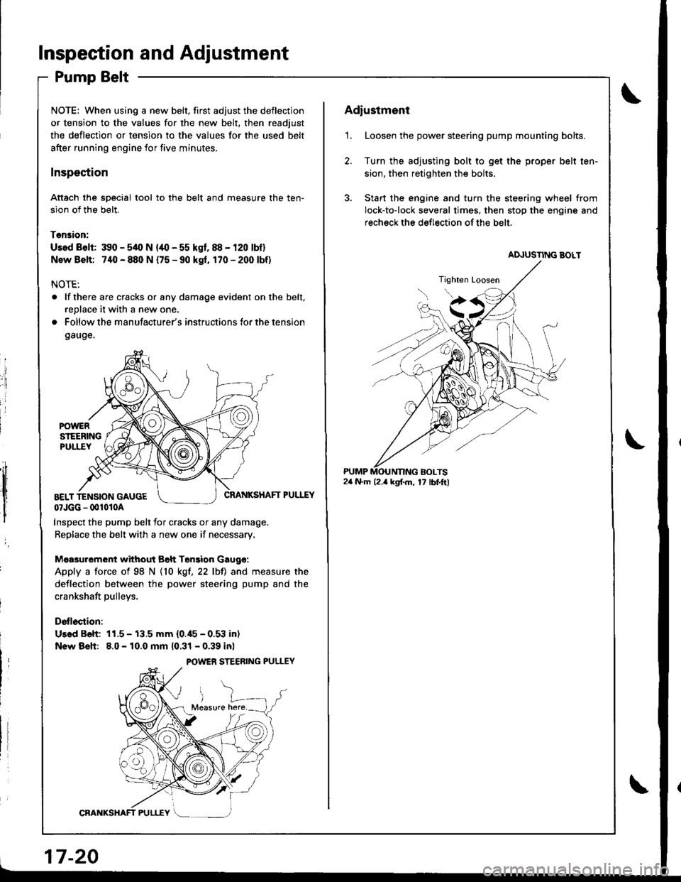
Inspection and Adjustment
Pump Belt
NOTE: When using a new belt, first adjust the deflection
or tension to the values for the new belt, then readjust
the deflection or tension to the values for the used belt
after running engine for five minutes,
Inspection
Attach the soecial tool to the belt and measure the ten-
sion of the belt.
Tension:
Usad Belt: 390 - 54O N {/10 - 55 kgf. 88 - 120 lbf}
Nsw Belt: 740 - 880 N {75 - 90 kgf. 170-2(X)lbf)
NOTE:
. lf there are cracks or any damage evident on the belt,
replace it with a new one.
. Follow the manufacturer's instructions for the tension
gauge.
ii
:i
i
I
,;h
,lt l
I
i
CRANKSHAFT PULEYBELT TENSION GAUGE07JGG - 001010A
Inspect the pump belt for cracks or any damage.
Replace the belt with a new one if necessary.
Mea3urement without Bah Tonsion Gaugo:
Apply a force of 98 N {10 kgt,22 lbll and measure the
deflection between the power steering pump and the
crankshaft pulleys,
Drllection:
Us.d B6h: 11.5 - 13.5 mm (0.45 - 0.53 in)
New Bsh: 8.0 - 10.0 mm 10.31 - 0.39 inl
POWER STEERING PULLEY
17-20
Adiustment
1. Loosen the power steering pump mounting bolts.
2. Turn the adjusting bolt to get the proper belt ten-
sion, then retighten the bolts.
3. Stan the engine and turn the steering wheel from
lock-to-lock several times. then stop the engine and
recheck the deflection of the belt.
24 N.m l2.a kgf.m, 17 lbf.ftl
Page 858 of 1680
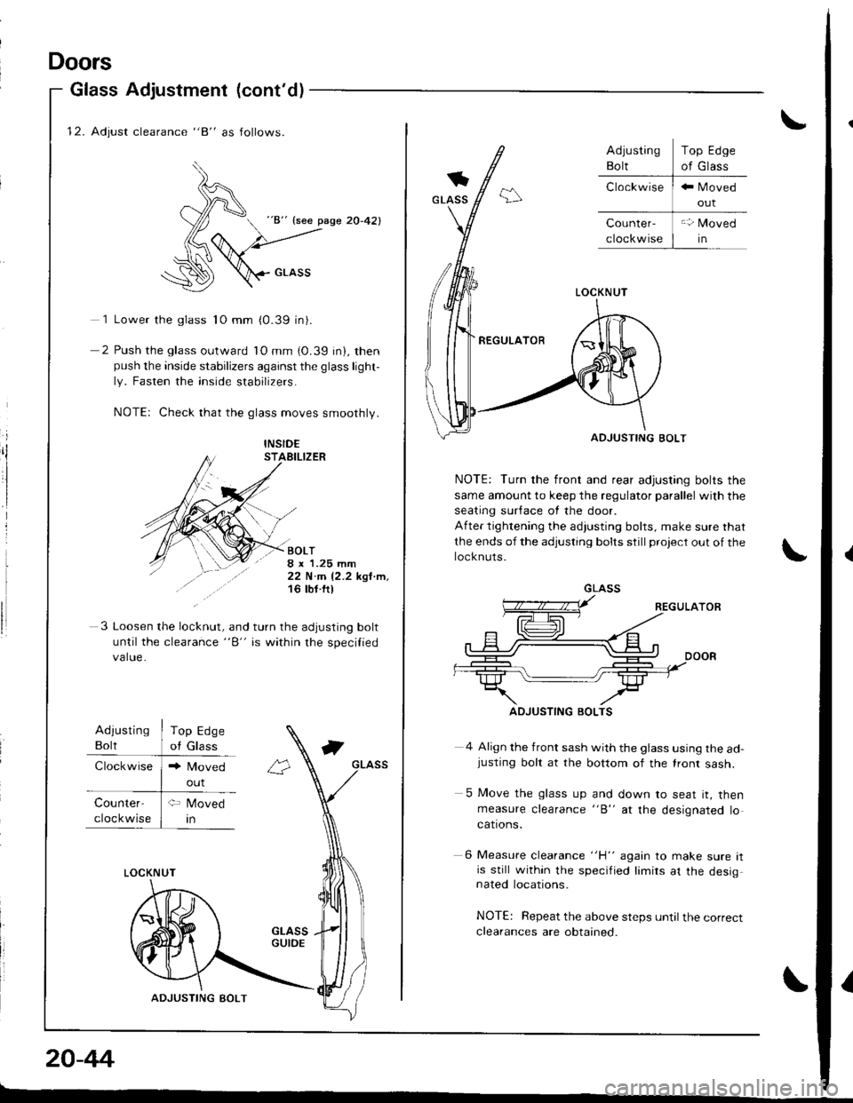
12. Adjust clearance "8" as follows.
)^
d "8" {see pase 20-42}
(6
:\D \crnss
1 Lower the glass 1O mm (0.39 in).
2 Push the glass outward lO mm (0.39 in), thenpush the inside stabilizers against the glass light-
ly. Fasten the inside stabilizers.
NOTE: Check that the glass moves smoothly.
i
ilINSID€STAEILIZER
BOLT8 x 1.25 mm22 N.m 12.2 kgl.m,16 tbt ftl
3 Loosen the lo"knrt, "nd turn the adjusting bolt
until the clearance "B" is within the specilied
value.
Adiusting
Bolt
Clockwise
Top Edge
of Glass
Counter-
cloc kwise
LOCKNUT
ADJUSTING BOLT
20-44
Doors
Glass Adjustment (cont'd)
out
\
LOCKNUT
REGULATOR
ADJUSTING BOLT
NOTE: Turn the front and rear adjusting bolts the
same amount to keep the regulator parallel with the
seating sur{ace ot the door.
After tightening the adjusting bolts, make sure that
the ends of the adjusting bolts still project out of the
locknuts.
4 Align the front sash with the glass using the ad-justing bolt at the bottom of the lront sash.
5 Move the glass up and down to seat it, thenmeasure clearance "B" at the designated locations.
6 Measure clearance "H" again to make sure itis still within the specified limirs at the desig,nated locations.
NOTE: Repeat the above steps until the correct
clearances are obtained.
Top Edge
of Glass
GLASS
ADJUSTING BOLTS
I
Page 860 of 1680
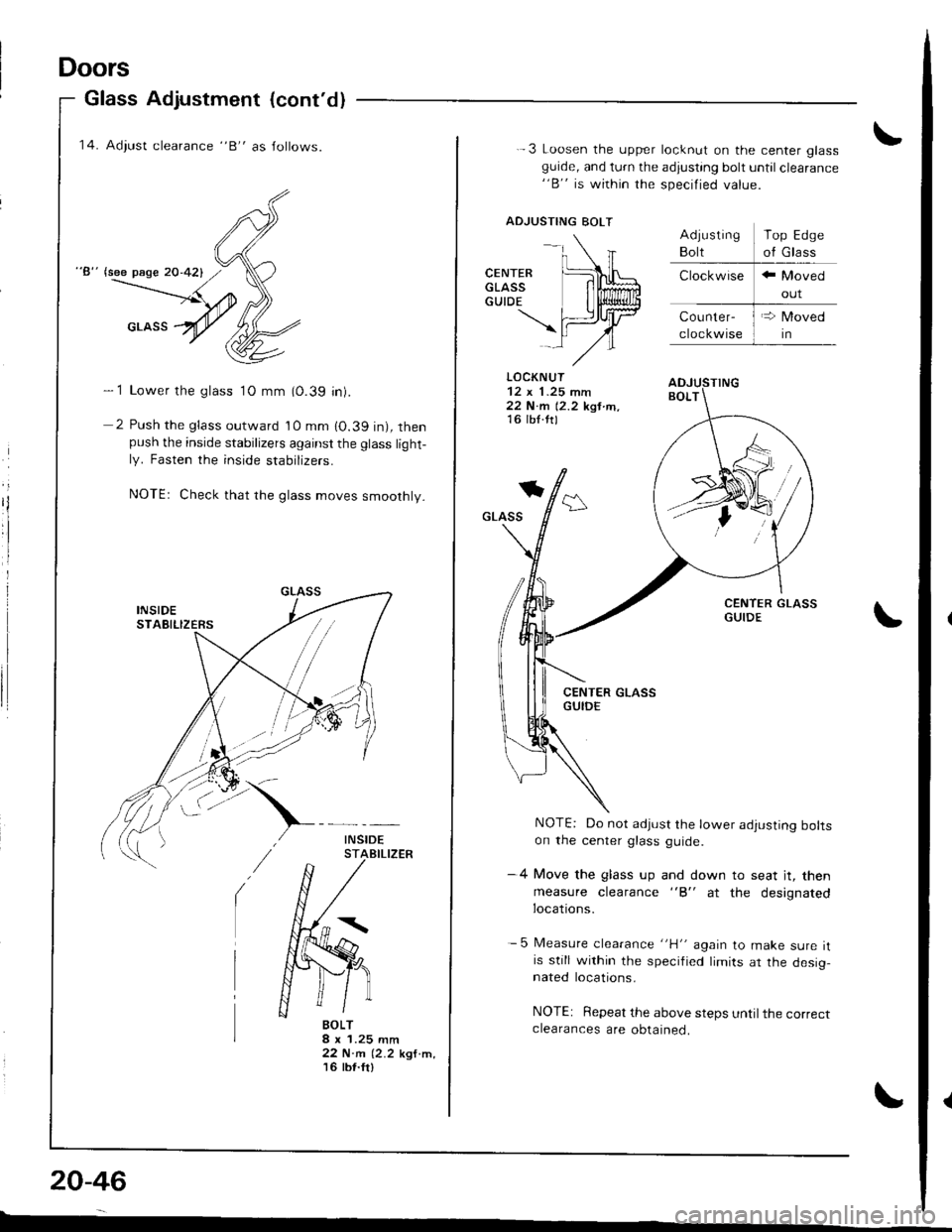
Doors
Glass Adjustment (cont'dl
'14. Adiust clearance "B" as Jollows.
"8" lsee page 20-421
- 1 Lower the glass 1O mm (0.39 in).
2 Push the glass outward 10 mm 10.39 in), thenpush the inside stabilizers against the glass light-ly. Fasten the inside stabrIzers.
NOTEr Check that rhe glass moves smoothly.
BOLT8 x 1.25 mm22 N.m (2.2 kgf.m,'t6 tbt.fr)
20-46
-
-.\
CENTER [L\LGLAss lilffiGUTDE I li$lliun
\fiJrtrlAl-,/"
.-3 Loosen the upper locknut on the center glassguide, and turn the adjusting bolt until clearance"B" is within the specified value.
ADJUSTING BOLT
LOCKNUT
22 N.m 12.2 kgt tn,16 lb{.ttl
*
GLASS
NOTE: Do not adjust the lower adjusting boltson the center glass guide.
-4 Move the glass up and down to seat jt, then
measure clearance "B" at the designatedlocations.
- 5 Measure clearance "H" again to make sure itis still within the specified limits ar the desig,nated locations.
NOTE: Repeat the above steps until the correctclearances are obtained.
Top Edge
of Glass
Page 1334 of 1680
)
Precautions/Procedures
General Precautions
Carefully inspect any SRS part before you install it,
Do not install any part that shows signs of being drop-
ped or improperly handled. such as dents, cracks or
deformstion:
- Airbags- Cable reel- SRS unit
' Use only a digital multimeter to check the system lf
it's not a Honda multimeter. make sure its output is
10 mA (0.01 A) or less when switched to the smallest
value in the ohmmeter range. A tester with a higher
output could damage the airbag circuit or cause acci-
dental deployment and possible injury.
r Do not install used SRS parts from anothercar.When
making SRS repairs, use only new parts.
r Except when performing electrical inspections,
always disconnect both the negative cable and posl-
tive cable from the batterY, and wait at least three
minutes before beginning work.
r Replacement of the combination light and wiper/
washer switches and cruise control switch can be
done without removing the steering wheel:
- Combination light and wiperlwasher switch replace-
ment (see page 23-268).- Cruise controi sevresume switch replacement (see
page 23-259t�.
. Whenever the ignition switch is ON (ll), or has been
turned OFF for less than three minutes, be caretul not
to bump the SRS unit; the airbags could accidentally
deploy and cause damage or iniuries.
. Whenever the airbag has been activated, replace the
SRS unit.
. The original radio has a coded theft protection circuit.
Be sure to get the customer's code number beJore dis-
connecting the battery cables.
23-281
Airbag Handling and Storage
Do not try to disassemble the airbag. lt has no service-
able parts. Once an airbag has been operated
(deployed), it cannot be repaired or reused.
For temporary storage of the airbag during service,
please observe the following precautions:
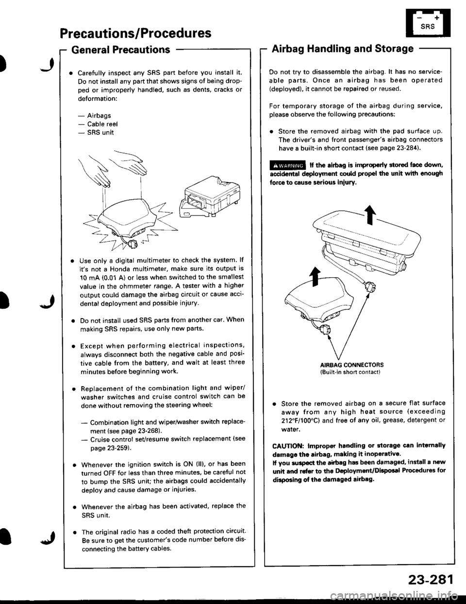
. Store the removed airbag with the pad surface up.
The driver's and tront passenger's airbag connectors
have 8 built-in short contact (see page 23-284).
@ r the airbag is improp€rly storcd face down,
accidental deployment could propel the unit with enough
force to caus6 serious iniury.
AIRBAG CONNECTORS(Built-in short contact)
. Store the removed airbag on a secure flat surface
away from any high heat source (exceeding
212F110O'CI and free of any oil, grease, detergent or
water.
CAUTION: lmproper handling or storage can intornally
damags the airbag, making it inoperative.
1l you su3pocl the aitbag has been damaged, install a ncw
unit and rofEr to ths Deployment/Dilpolal Procedures for
dbposing of ihe damsged ailbag.
)