ACURA INTEGRA 1998 Service Repair Manual
Manufacturer: ACURA, Model Year: 1998, Model line: INTEGRA, Model: ACURA INTEGRA 1998Pages: 1680, PDF Size: 53.14 MB
Page 351 of 1680
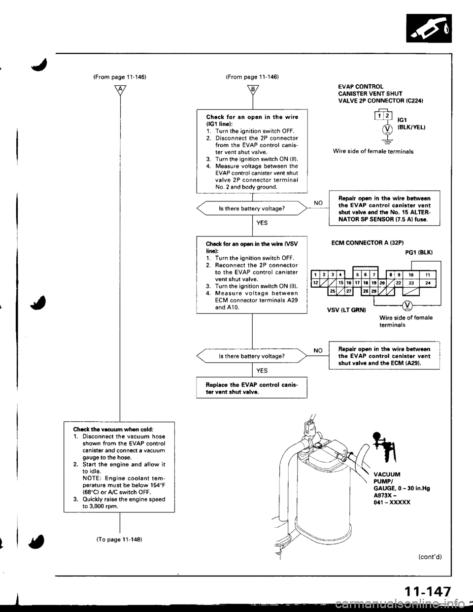
(From psge 11-146)
(To page 11-148)
Chack tho vldlum wh.n cold:'1. Disconnscl the vacuum hoseshown from the EVAP controlcanrster ano connect a vacuumgauge to the hose.2. Start the engine and aliow itto idls.NOTE: Engine coolant tem-porat{rre must be below 154"F{68'C} or A/C switch OFF.3. Ouickly raise the engine speedto 3,000 rpm.
lFrom page 11-146)
Check lor an opon in lhe wir€(lG1 lin6l:1. Turn the ignition switch OFF.2. Disconnect the 2P connectorlrom the EVAP control canis-ter vent shut valve.3. Turn the ignition switch ON (ll).
4. Measure voltage between theEVAP control canister vent shutvalve 2P connector terminalNo. 2 and body ground.
Ropair open in the wir6 betweonthe EVAP control canistor v6ntshut valve end the No. 15 ALTER-NATOR SP SENSOR 17.5 Al tu!e.
Ch€ck tor rn op€n in iho wire IVSVline):1. Turn tho ignition switch OFF.2. Reconnect the 2P connectorto the EVAP control canistervent shut valve,3. Turn the ignition switch ON (ll).
4, Measure vo ltage betweenECN/l connector terminals A29and A10.
Repair open in the wire beiwa€nthe EVAP cont.ol cenister ventshut valve and the EcM {4291.ls there baftery vohage?
ReDlacs tho EVAP cont.ol canis"ter vent shut valve.
EVAP CONTROLCANISTER VENT SHUIVALVE 2P CONNECTOR IC224)
.FJ.\1121-T rcl
(D (BLK/YEL)
I
Wire side ot female terminals
ECM CONNECIOR A {32P}
VSV ILT GRNI
Wire side of femaletermtnars
VACUUMPUMP/GAUGE,0 - 30 in.H94973X -
0a1 - xxxxx
(cont'd )
11-147
PG1 (BLKI
rl
4lq-r'rri l12t5t6t?l8r@llzzlzslul
25212a2
__l
Page 352 of 1680
Emission Control System
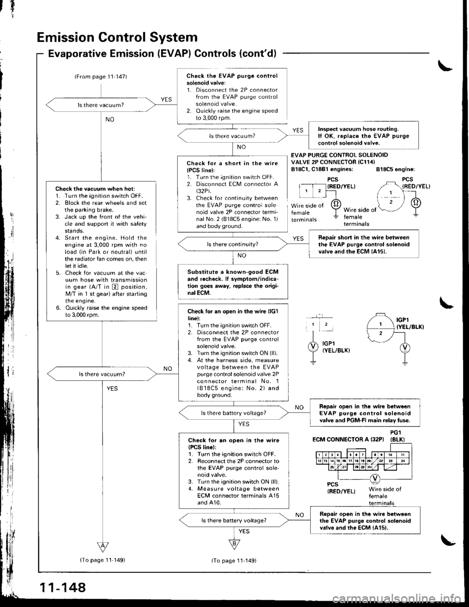
Check the vacuum when hot:1. Turn the ignition switch OFF.2. Block the rear wheels and setthe parking brake.3. Jack up the front of the vehi-cle and support it with safetystands.4- Start the engine. Hold theengine at 3,000 rpm with noload (in Park or neutral) untilthe radiator fan comes on, thenlet it idle.5. Check for vacuum at the vacuum hose with transmissionin gear (A/T in E position,M/T in 'l st gear) after startingrne engrne.6. Ouickly raise the engine speedto 3,000 rpm.
Evaporative Emission (EVAP) Controls (cont'd)
(From page 1'l 147)Check the EVAP purge controlsolenoid valve:1. Disconnect the 2P connectorfrom the EVAP purge controlsolenoid valve.2. Ouickly raise the engine speedto 3,000 rpm.
{To page 11 149)
tfl'I
Check lor a short in the wire{PCS line}l1. Turn the ignition switch OFF.2. Disconnect ECM connector A(32P).
3. Check for continuity betweenthe EVAP purge control solenoid valve 2P connector termi-nal No. 2 (818C5 engine: No. 1)and body ground.
Check for an open in the wire llclline):1. Turn the ignition switch OFF.2, Disconnect the 2P connectorfrom the EVAP purge controlsolenoid valve.3. Turn the ignition switch ON (ll).
4. At the harness side, measurevo ltage between the EVAPpurge controlsolenoid valve 2Pco n nector terminal No. 1( B 18C5 engine: No. 2) andbody ground.
EVAP PURGE CONTROI SOLENOIDVALVE 2P CONNECTOR IC114)B18C1, Cl8Bl engines: 818C5 engine:
PCSIRED/YEL}
femaleWire side offemaleterminals
YES
IGPl{YEL/BLKI
IGPlIYEL/BLKI
ECM CONNECTOR A {32PIPG1IBLKI
Insp€ct vacuum hose routing.lf OK, replace the EVAP purge
control solenoid valve.
neDair short in the wire betweenthe EVAP purge control solenoidvalve and the ECM lAl5).
Substitute a known-90od ECMand recheck. lI symptom/indica-tion goes away, replace the origi-nal ECM.
Repair open in the wirc betweenEVAP purge control solenoidvalve and PGM-FI main relav fuse.ls there battery voltage?
Check for an open in the wireIPCS linel:1. Turn the ignition switch OFF.2. Reconnect the 2P connector tothe EVAP purge control sole'noid valve.3. Turn the ignition switch ON (ll).
4. Measure voltage betweenECM connector terminals A15and A10.
Bopair open in the wiro betweenthe EVAP purgo control 3olanoidvalvo and the EcM {415).
11-144
(To page 11-149)
Page 353 of 1680
{From1 1-148)page
v
(From page 11 148)
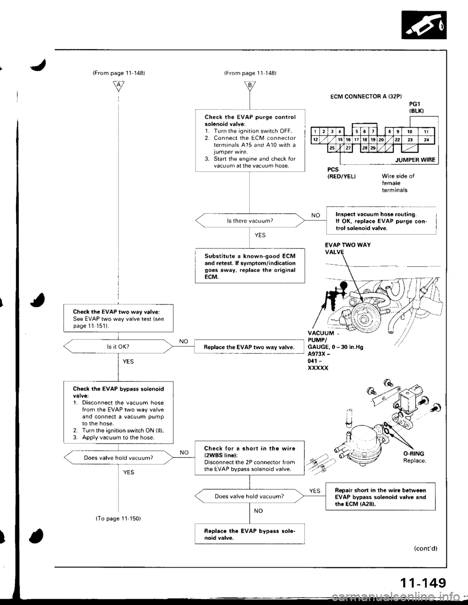
Substitute a known-good ECMand retest. lf svmplom/indicationgoes away, replace the originalECM,
ECM CONNECTOR A {32PIPG1{8LKI
PCSIRED/YEL)femaletermrnars
Inspect vacuum hose routing.It OK, replace EVAP purge con-trol solenoid valve.
Check the EVAP purge controlsolenoid valve:1. Turn lhe ignition switch OFF.2, Connect the ECM connectorterminals 415 and 410 with a
3. Start the engine and check forvacuum at the vacuum hose.
ls there vacuum?
EVAP TWO WAY
Check the EVAP two way valvelSee EVAP two way valve test (seepage 11 '151).
Replace the EVAP two way valve.
Check the EVAP bypass solenoid
1. Disconnect the vacuum hosefrom the EVAP two way valveand connect a vacuum pumpto the hose.2. Turn the ignition switch ON (lli.
3. Apply vacuum to the hose.
Check lor a short in the wire{2WBS linel:Disconnect the 2P connector fromthe EVAP bypass solenoid valve.
Does valve hold vacuum?
Repair short in tho wire betweenEVAP bypass solonoid valve andrhe ECM {A28).
Does valve hold vacuum?
(cont'd)
{To page 11 150)
11-149
Page 354 of 1680
fIr
Emission Control System
Evaporative Emission Controls (cont'dl
t
ECM CONNECTOR A I32PI
JUMPERWIRE
EVAP BYPASS SOLENOIDVALVE 2P CONNECTOB (C793I
tGl(BLK/WHTIWire side of
femaleterminals
\
ECM CONNECTOR A (32PI
PGl (BLKI
Wire side of lem6l6termrnals
(From page 11-149)
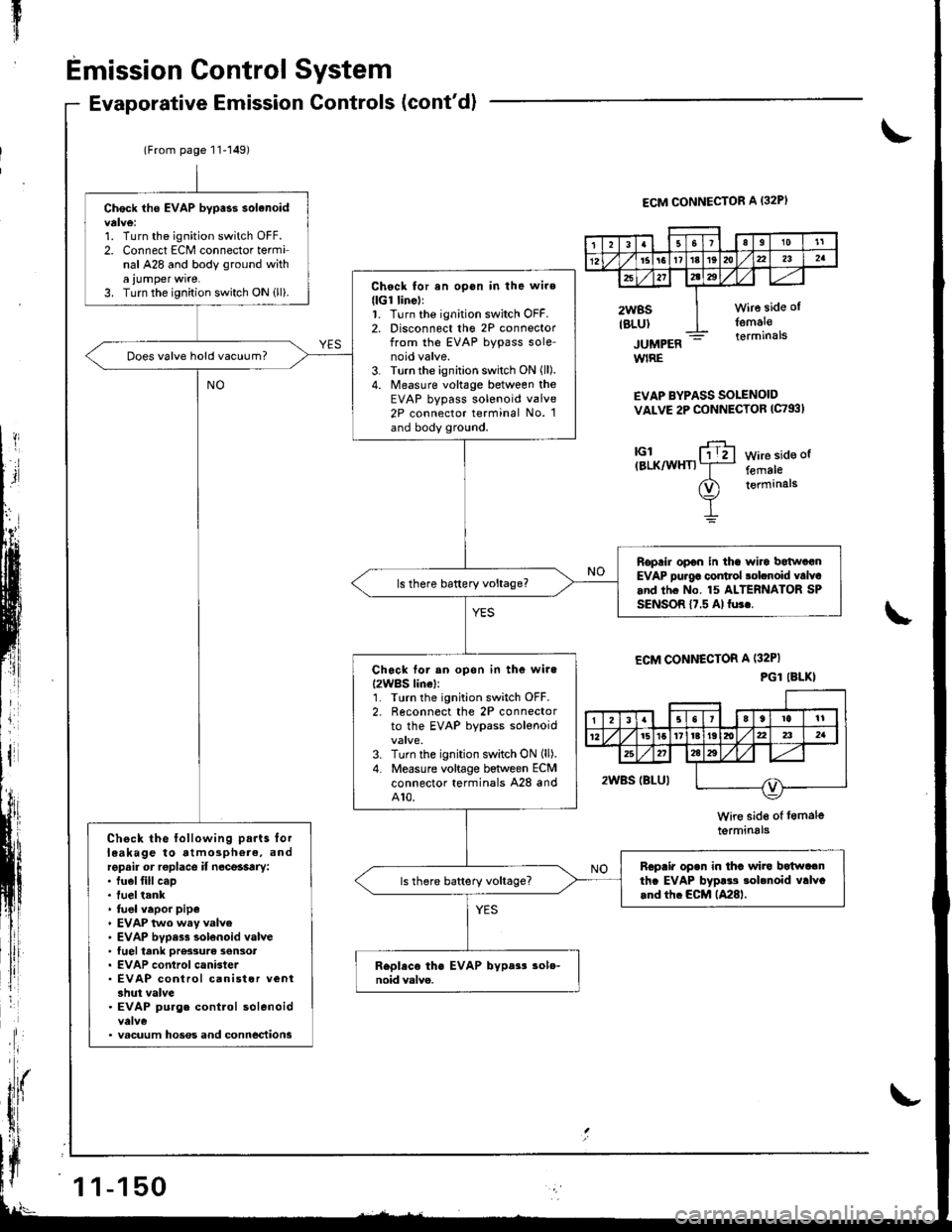
Check iho EVAP bypass solanoid
1. Turn the ignitioo switch OFF.2. Connect ECM connector terminal A28 and body ground witha ,umper wrre.3. Turn the ignition switch ON ill).Chock for an opon in the wire(lGr linell1. Turn the ignition switch OFF.2. Disconnect tho 2P connectorfrom the EVAP bypass sole-noid valve.3. Turn the ignition switch ON (ll).
4. Measure voltage between theEVAP bypass solenoid valve2P connector terminal No. 1and body ground.
Does valve hold vacuum?
Roprir opon in tha wiro batwatanEVAP pu.g6 control solcnoid valvcand thc No. 15 ALTERNATOR SPSENSOR {7.5 Al fu3..
Ch6ck tor an opon in the wile
I2WBS lin6l:'L Tlrrn the ignition switch OFF.2. Reconnect the 2P connectorto the EVAP bypass solenoid
3. Turn the ignition switch ON (ll).
4. Measure voltage between ECMconnector terminals A28 andA10.
Check the following parts lorleakage to atmosphere, andrepsir or roplace if n6ce$try:. fuel fill cap. fuel tank' fuel vapor pipe. EVAP two wsy valve. EVAP bvpess solenoid valve. tuel tank ore33urc son3ot. EVAP control canister. EVAP control canist6r veni3hut valve. EVAP purg. control solenoid
. vacuum hoses and conn6ctions
Rcpair opan in thc wira botwa.nth. EVAP byp!.s sobnoid valvc.nd tfi. ECM lA28l.
3Ia10't1
12l61611t8t9dta22a2a
x272tz3
2WBSIBLUI
wire side ol
femal€terminals
1 1-150
Page 355 of 1680
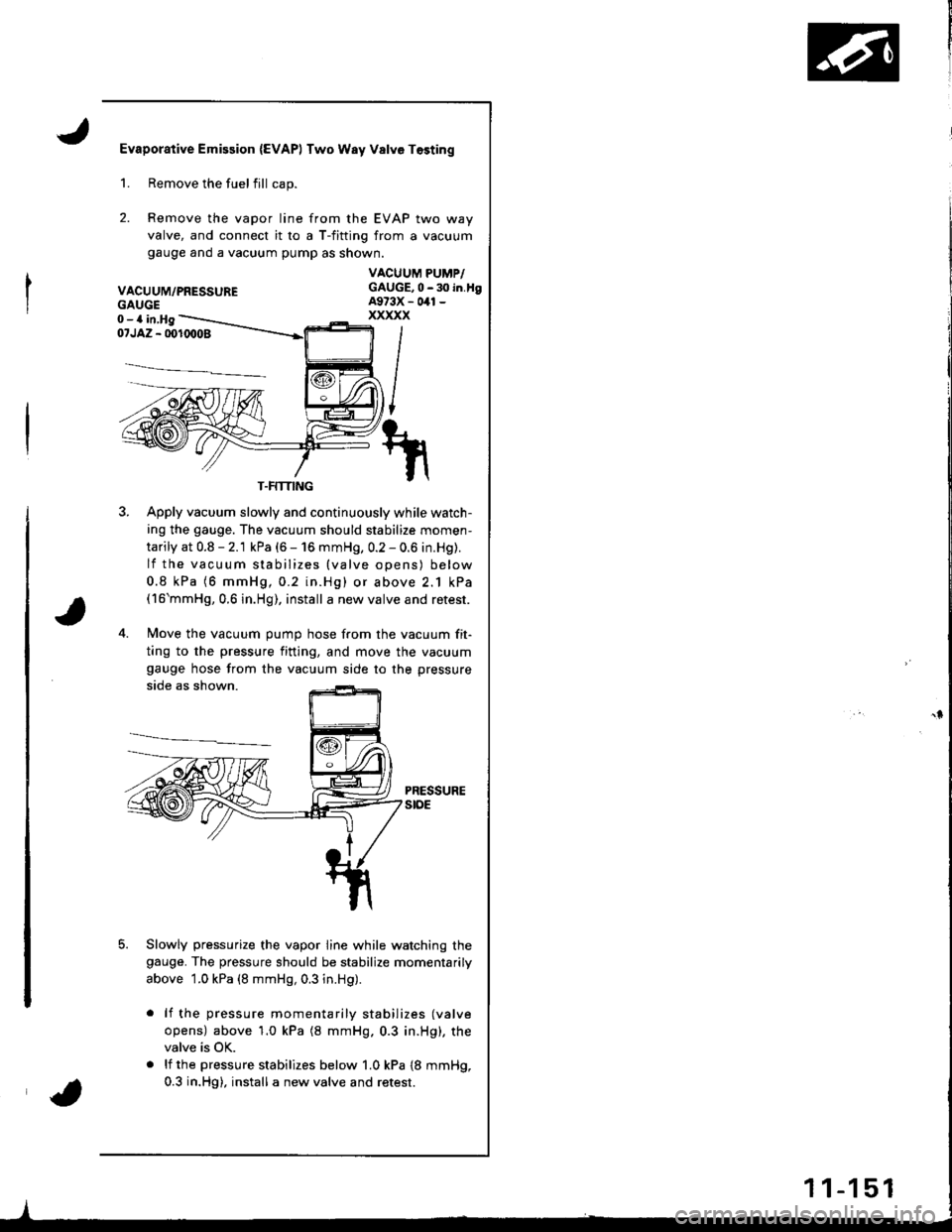
Evaporative Emission {EVAPI Two Way Valve Tosting
2.
Remove the fuelfill cap.
Remove the vapor line from the EVAP two way
valve, and connect it ro a T-fitting from a vacuum
gauge ano a vacuum pump as shown.
VACUUM/PRESSURE
1.
GAUGE0-a in,Hg
VACUUM PUMP/GAUGE,0 - 30 in.tlgA973X - 041 -
xxxxx
i/NI
t/
il\/
1il|
07JAZ - 001(X)08
3. Apply vacuum slowly and continuously while watch-
ing the gauge. The vacuum should stabilize momen-
tarily at 0.8 - 2.1 kPa (6 - 16 mmHg, 0.2 - 0.6 in.Hg).
lf the vacuum stabilizes {valve opens) below
0.8 kPa (6 mmHg,0.2 in.Hg) or above 2.1 kPa(16'mmHg,0.6 in.Hg), install a new valve and retest.
4. Move the vacuum oumo hose from the vacuum fit-
ting to the pressure fining, and move the vacuum
gauge hose from the vacuum side to the pressure
side as shown.
PRESSUREstoE
Slowly pressurize the vapor line while watching thegauge. The pressure should be stabilize momentarily
above 1.0 kPa (8 mmHg, 0.3 in.Hg).
lf the pressure momentarily stabilizes (valve
opens) above'1.0 kPa (8 mmHg.0.3 in.Hg), the
valve is OK.
lf the pressure stabilizes below 1.0 kPa {8 mmHg,
0.3 in.Hg), install a new valve and retest.
T.FMING
1 1-1 51
Page 356 of 1680
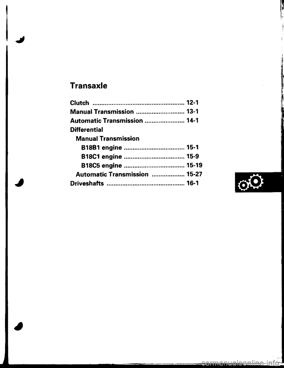
Transaxle
Clutch ...........12-1
Manual Transmission ............................ 13-1
Automatic Transmission ....................... 1 4-1
Differential
Manual Transmission
B1881 engine ................................... 15-1
818C1 engine ................................... 15-9
B18C5 engine .............. 15-19
Automatic Transmission ................. .. 15-27
Driveshafts ... 16-1
Page 357 of 1680
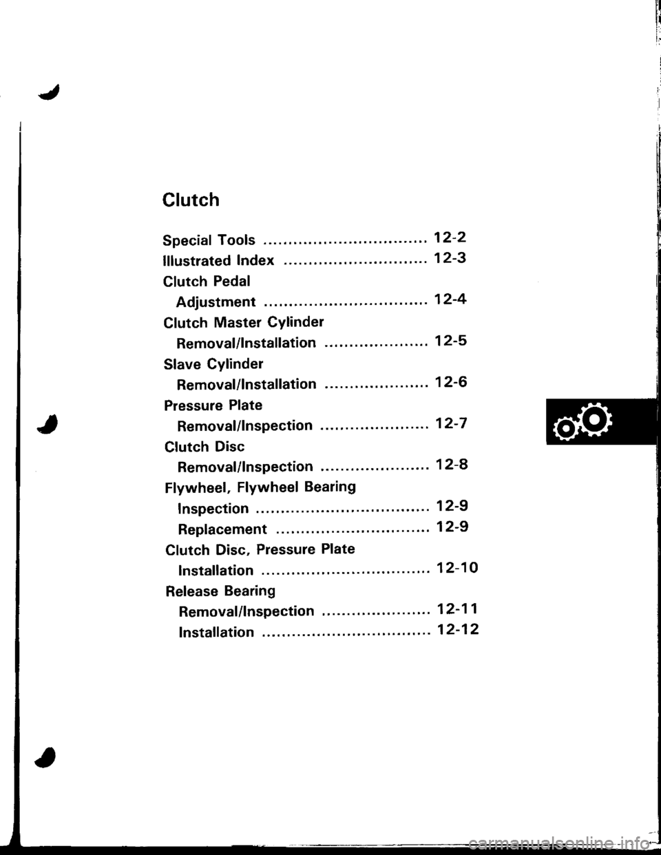
Clutch
Speciaf Tools ........ .'--"" 12-2
lflustrated Index ........ ".' 12-3
Clutch Pedal
Adjustment "..".""'...' 12-4
Clutch Master Cylinder
Removal/lnstallation -'.' 12-5
Slave Cylinder
Removal/lnstallation '..' 12-6
Pressure Plate
Removal/lnspection .'-.' 12-7
Clutch Disc
Removal/lnspection '...' 12-a
Flywheel, Flywheel Bearing
fnspection ' 12-9
Replacement .................'............. 1 2-9
Clutch Disc, Pressure Plate
lnstallation ................. 12-10
Release Bearing
Removal/lnspection "'.' 12-11
fnstaffation ".""".-'."'. 12-12
Page 358 of 1680
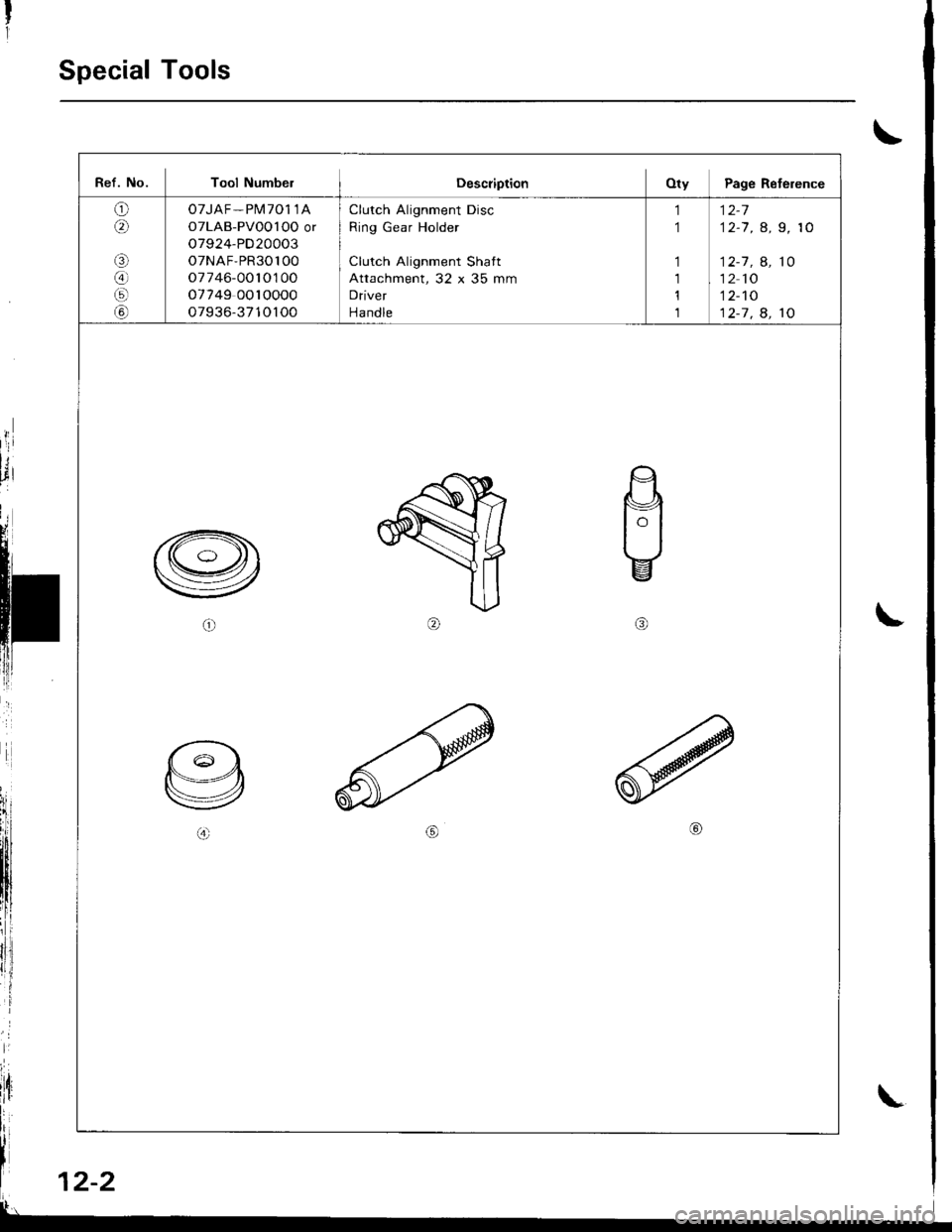
Special Tools
\
t
rl
;
lt, 12-2
Ref. No. Tool NumbelDescriptionOty Page Reference
o6\
aa
G)
07JAF - Pl\il701 1A
OTLAB-PVoO l OO or
o7924-PD20003
o7NAF,PR30100
o7746-0010100
o7749 0010000
o7936-3710100
Clutch Alignment Disc
Ring Gear Holder
Clutch Alignment Shatt
Attachment, 32 x 35 mm
Driver
Handle
1
1
1
1,l
1
12-7
12-7 , a, 9, 10
12-1 , A, 10
12 10
12-'tO
12-7 . 8. 10
\
Page 359 of 1680
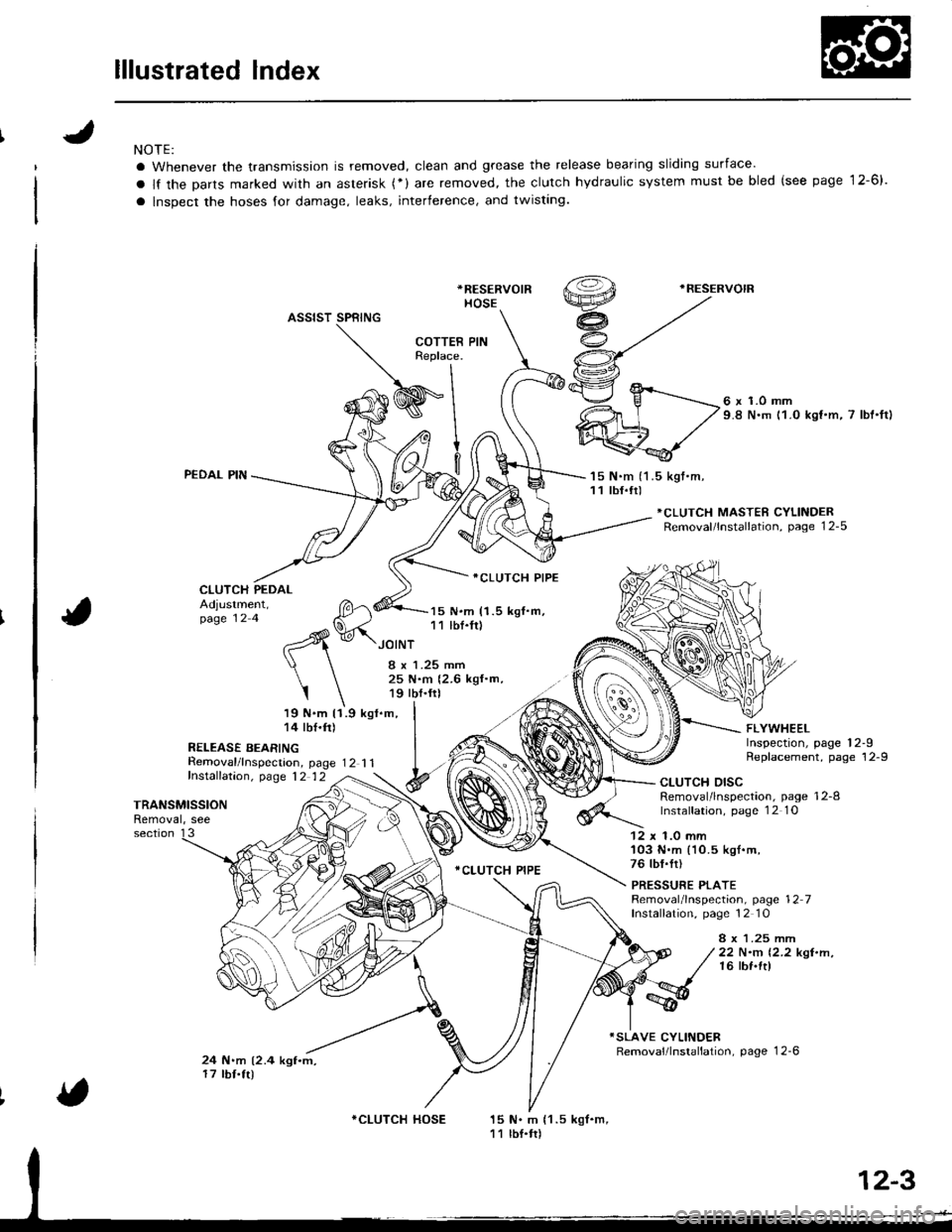
lllustrated Index
NOTE:
a Whenever the transmission is removed, clean and grease the release bearing sliding surface'
a lf the Darts marked with an asterisk (*) are removed, the clutch hydraulic system must be bled (see page 12-6).
a lnspect the hoses for damage, leaks, interference, and twisting.
*RESERVOIR
HOSE
.RESERVOIR
ASSIST SPRING
PEDAL PIN
CLUTCH PEDAL
Removal/lnspecrion, page 12 1 1fnstalfation, p,age 12 12
6 x 1.0 mm9.8 N.m 11.0 kst.m, 7 lbt'ftl
'15 N.m (1 .5 kgt.m,11 tbf.tr)
*CLUTCH MASTER CYLINDERRemoval/lnstallation, page 12-5
Adjustment,page 12 4
19 N.m 11.9 kgl.m,14 tbf.ft)
R€LEASE BEARING
15 N.m (1.5 kgf.m,11 lbf.fr)
ICLUTCH PIPE
.CLUTCH PIPE
FLYWHEELInspection, page 12-9Replacement, page 12-9
JOINT
I x 1.25 mm25 N.m {2.6 kgf.m,19 tbf.frl
I
TRANSMISSIONRemoval, see
CLUTCH DISCRemoval/lnspection, page 12-8lnstalfation, page 1 2 1O
section 1312 x 1.0 mm'103 N.m (10.5 kgl.m,76 tbf.fr)
PRESSURE PLATERemoval/lnspection, page 12 7Installation, page 12 10
8 x 1.25 mrr|22 N.m 12.2 kgt.n,16 lbf.ft)
24 N.m (2.4 kgf.m,17 tbf.tr)
15 N. m {1 .5 kgf.m,11 lbf.tr)
COTTERReplace.
I
WInl
9l
v.^- fl
*CLUTCH HOSE
Page 360 of 1680
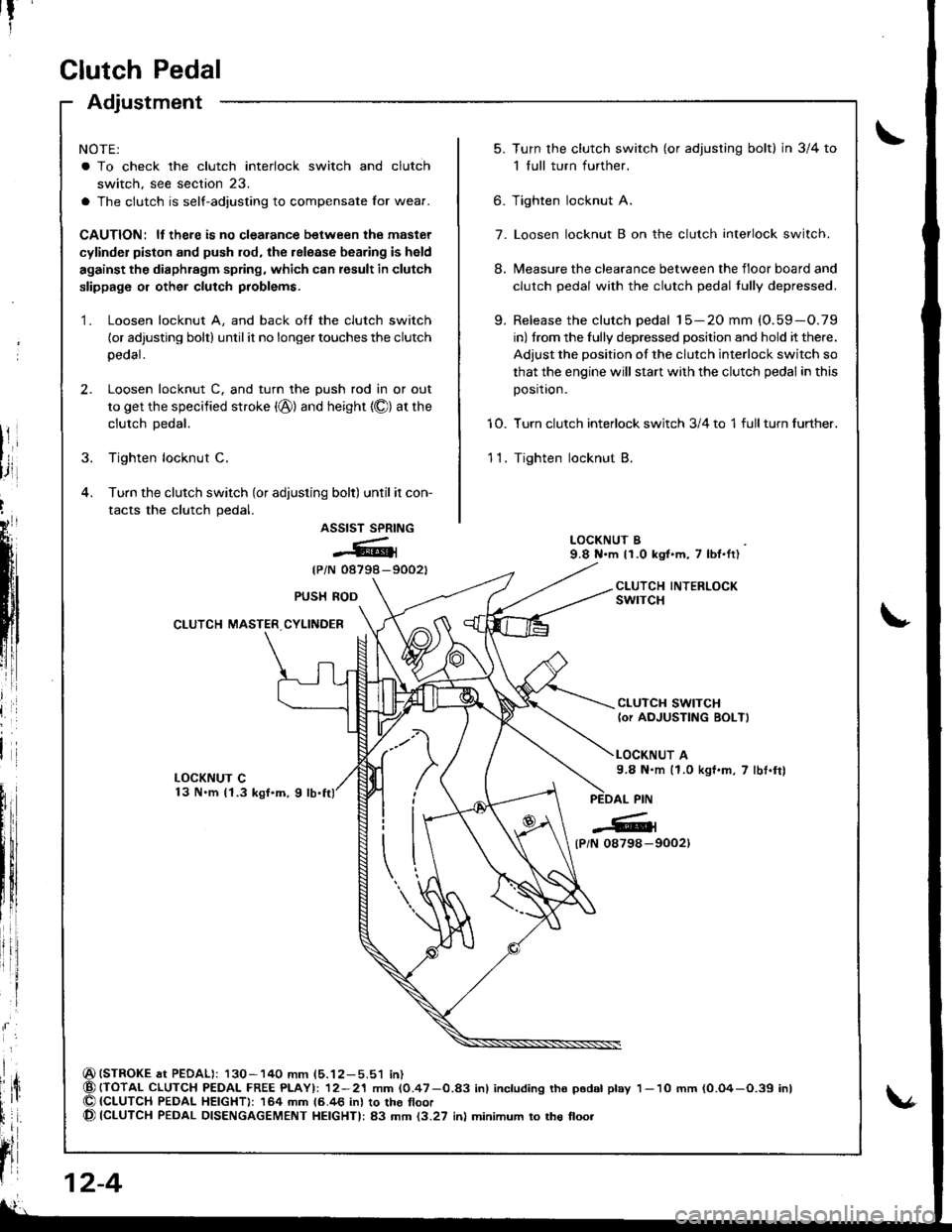
Clutch Pedal
Adjustment
NOTE:
a To check the clutch interlock switch and clutch
switch, see section 23.
a The clutch is self-adjusting to compensate Ior wear.
CAUTION: ll there is no clealance between the master
cylinder piston and push rod, the release bearing is held
against the diaphragm spring, which can result in clutch
slippage or other clutch problems.
1. Loosen locknut A, and back off the clutch switch
(or adjusting bolt) until it no longer touches the clutch
peoal.
2. Loosen locknut C. and turn the push rod in or out
to get the specified stroke (@) and height {O) at the
clutch Dedal.
3. Tighten locknut C.
4. Turn the clutch switch (or adjusting bolt) until it con-
tacts the clutch pedal.
ASSIST SPRING
@{
{PiN 08798-9002t
(STROKE at PEDAL): 130-140 mm (5.12-5.51 in){TOTAL CLUTCH PEDAI- FREE PLAYI: 12-21 mm (0.47-0.83 inl including tho p6dal play{CLUTCH PEDAL HEIGHT): 164 mm 16.46 inl to the tloor(CLUTCH PEDAL DISENGAGEMENT HEIGHTI: 83 mm {3.27 inl minimum to the floo.
t?
5.Turn the clutch switch (or adjusring bolt) in 3/4 to
1 full turn further.
Tighten locknut A.
Loosen locknut B on the clutch interlock switch.
Measure the clearance between the floor board and
clutch pedal with the clutch pedal tully depressed.
Release the clutch pedal 15-20 mm (O.59-O.79
in) from the fully depressed position and hold it there.
Adjust the position of the clutch interlock switch so
that the engine will stan with the clutch pedal in this
position.
Turn clutch interlock switch 3/4 to 1 full turn further.
Tighten locknut B.
9.
6.
7.
8.
10.
11.
LOCKNUT B9.8 N.m 11.0 kgt.m, 7 lbl.ft)
CLUTCH INTERLOCKswrTcHPUSH ROD
CLUTCH MASTER CYLINDER
CLUTCH SWITCH(or AOJUSTING BOLT)
LOCKNUT A9.8 N.m (1.0 kgf.m, 7 lbt.frl
l
{P/N 0879a-9002)
12-4
1- 10 mm (0.O4-O.39 inl