electrical ACURA INTEGRA 1998 Service Owner's Guide
[x] Cancel search | Manufacturer: ACURA, Model Year: 1998, Model line: INTEGRA, Model: ACURA INTEGRA 1998Pages: 1680, PDF Size: 53.14 MB
Page 490 of 1680
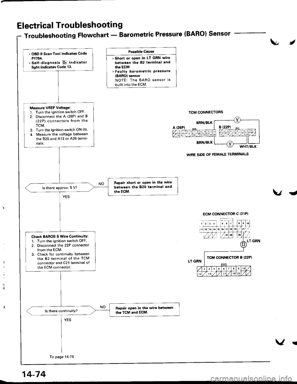
Electrical Troubleshooting
Troubleshooting Flowchart - Barometric Pressure (BARO) Sensor
t\l,
l
'|
. OBD ll Scan Tool lndicatos Code
P1794.. Self-diagnosis El indicator
light indicatos Code 13.
Check BAROS S Wire ContinuitY:1. Turn the ignition switch OFF.
2. Disconnect the 22P connedortrom the ECM.3. Check for continuity betweenthe 82 terminal ot the TCM
connector and C21 terminal of
the ECM connector.
PGsible cau3€
' Short ot oDen in LT GRN wite
betwoen the 82 lcrminal and
ihe ECM. Faulty baromotric PrelsureIBAROI ignsolNOTE: Tho BAFO sensor is
built into the ECM.
VqJ
WIRE SIDE OF FEMALE TERMINALS
Measure VREF Volttge:1. Turn the ignition switch OFF.
2. Disconnect the A (26P) and B(22 P) connectors from the
TCM.3. Turn the ignition switch ON {ll}.
4. Measure the voltage between
the 820 and 413 or 426 termi-
nals,
Repair shon or oPen in the wite
betwcon the 820 tsrminal and
tho EcM.ls there approx.5 V?
Repair open in the wiro betwoon
the TcM and ECM.ls there continuity?
To page 14-75
14-74
V!
Page 492 of 1680
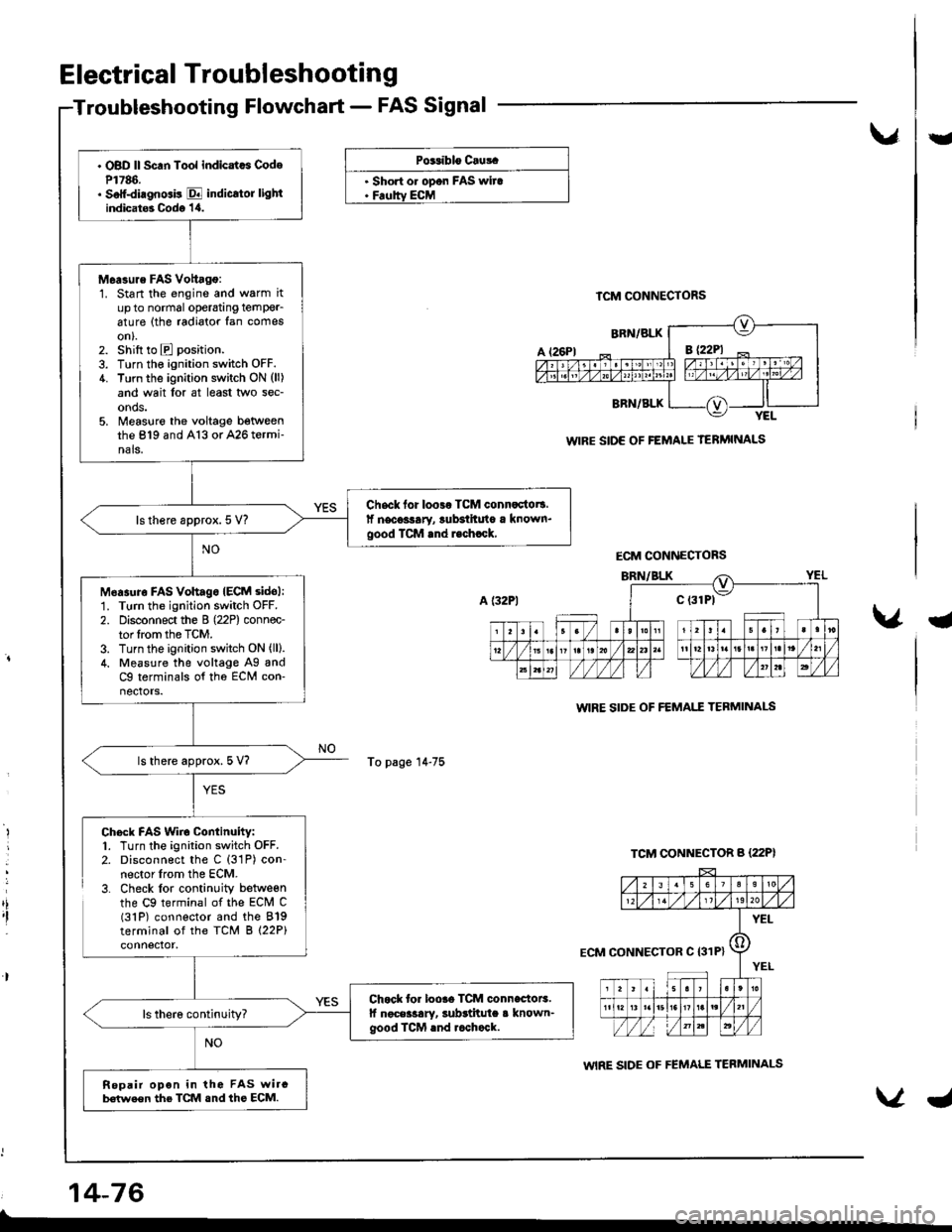
. OBD ll Scan Tool indicatcs CodeP1786.. Soff-diagnGis E indicrtor lightindicat6 Codo '1,0.
M6a3ure FAS Vottago:1. Start the engine and warm itup to normal operatang temPer_6ture (the radiator fan comeson).2. shift to E position.
3. Turn the ignition switch OFF.4. Turn the ignition switch ON (ll)
and wait lor at least two sec-onds.5. Measlre the voltage betweenthe 819 and A13 or A26 termi-nals.
Chsck for loo3r TCM connactot!.lf necoslary, lubsihuto a known.good TCM rnd r.chrck,ls there approx. 5 V?
M6asuro FAs vohagoIECM sidol:1. Turn the ignition switch OFF.
2. Disconnect the B (22P) connec-tor lrom the TCM.3. Turn the ignition switch ON (ll).
4. Measure the voltage Ag andC9 terminals of tho ECM con-nectors.
ls there approx. 5 V?
Chock for loore TCM connectoE.lf noceilary, subrtitula a known-good ICM rnd rcchock.
Repair opon in the FAS wircb€(we€n the TCM snd ths ECM.
Electrical Troubleshooting
Troubleshooting Flowchart - FAS Signal
vU
PG.iblo Cru!.
. Short o. opon FAS wira. Feoltv ECM
To page 14-75
TCM CONNECTORS
WIRE SIDE OF FEMALE TERMINALS
WIRE SIDE OF FEMAI.T TEBMINAI-S
WIRE SIDE OF FEMALE TERMINALS
a
,i,I
Chock FAS Wiro Continuity:1. Turn the ignition switch OFF.2. Disconnect the C (31P) con-nector lrom the ECM.3. Check lor continuity betweenthe C9 terminal of the ECM C(31P) connector and the 819terminal of the TCM B (22P)
14-76
ECM CONNECTORS
ECM CONNECTOR C I31P}
Page 494 of 1680
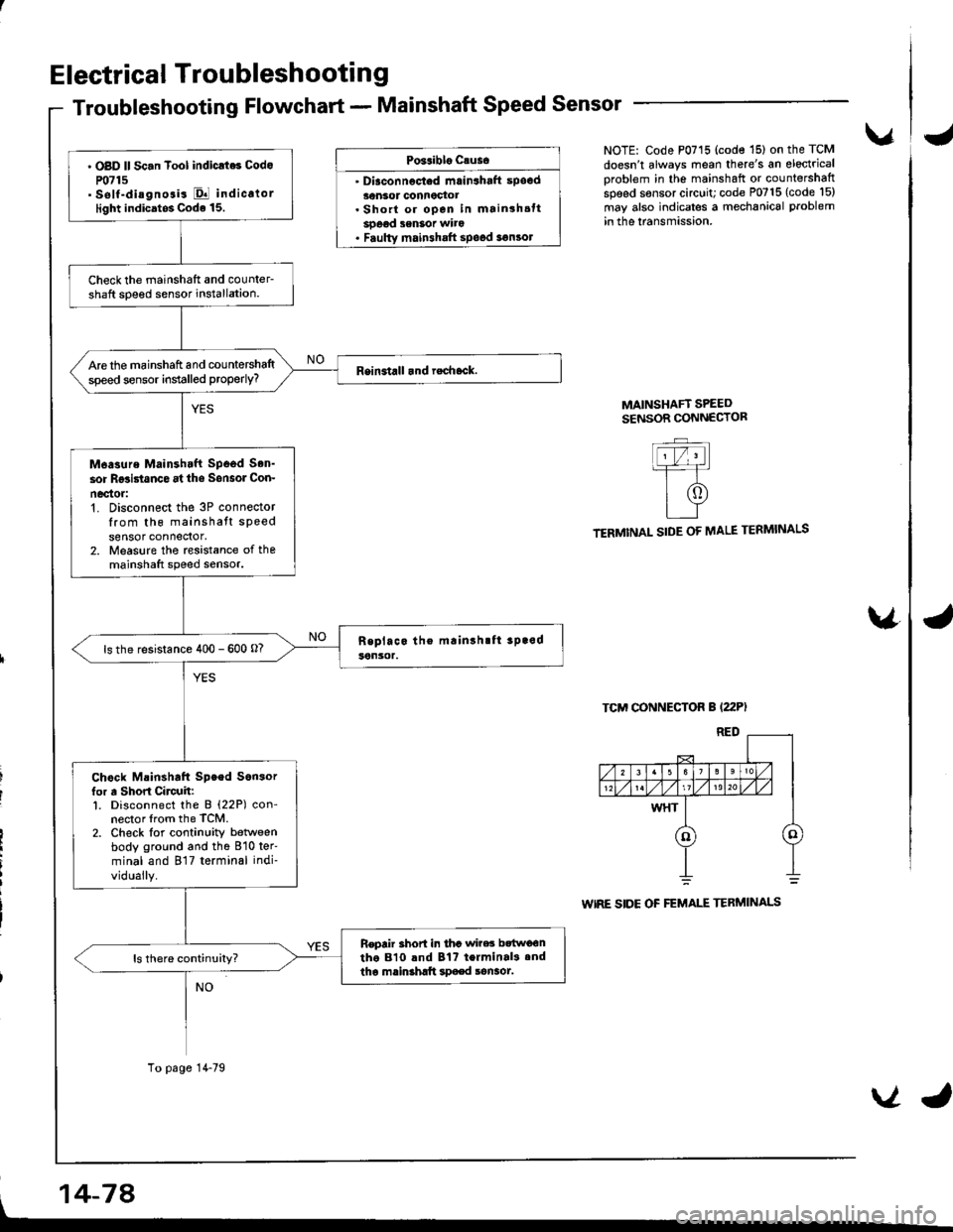
Electrical Troubleshootin g
Troubleshooting Flowchart - Mainshaft Speed Sensor
Po3aiblo causo
' Diaconnocted mrin3haft spocd30nsor connoctot. Short or open in mainshsttsoeod senSot wito. Faulty main3halt spood 3€n3ol
vNOTE: Code P0715 (code '15) on the TCM
doesn't always mean there's an electrical
oroblem in the mainshaft or countershaftspeed sensor circuit; code P0715 (code l5)
may also indicates a mechanical problem
in the lransmission.
MAINSHAFT SPEEDSENSOR CONNECTOR
TERMINAL SIDE OF MALE TERMINALS
TCM CONNECTOR B (22P)
WIRE SIDE OF FEMALE TERMINALS
\4
' OBD ll Sc.n Tool indicrt6 Codo
P0715' self-diagnosis El indicalorlight indicatos Code 15.
Check the mainshatt and counler-shaft soeed sensor installation.
Are the mainshaft and countershaltspeed sensor installed properly?
M6asure Mainshtft Spood Son'
sor Rgsi5tanco at ths Sonsol Con-
nec'tor:'t. Disconnect the 3P connectorIrom th6 mainshatt speedsensor connedor,2. Measure the rcsistance of themainshaft speed sensor.
ls the resistance 400 - 600 o?
Chock Mainshaft Speed Son3orfor a Short Circuh:l. Disconnect the B (22P) con-nector lrom the TCM.2. Check lor continuity betlveenbody ground and the 810 ter'
minal and 817 terminal indi-
vidually.
Repair 3hort in tha wi?es bttwo€ntho 810 lnd Bt? terminal3.ndtha mainshltt spaed sonaot.
To page 14-79
, 14-74
VJ
Page 496 of 1680
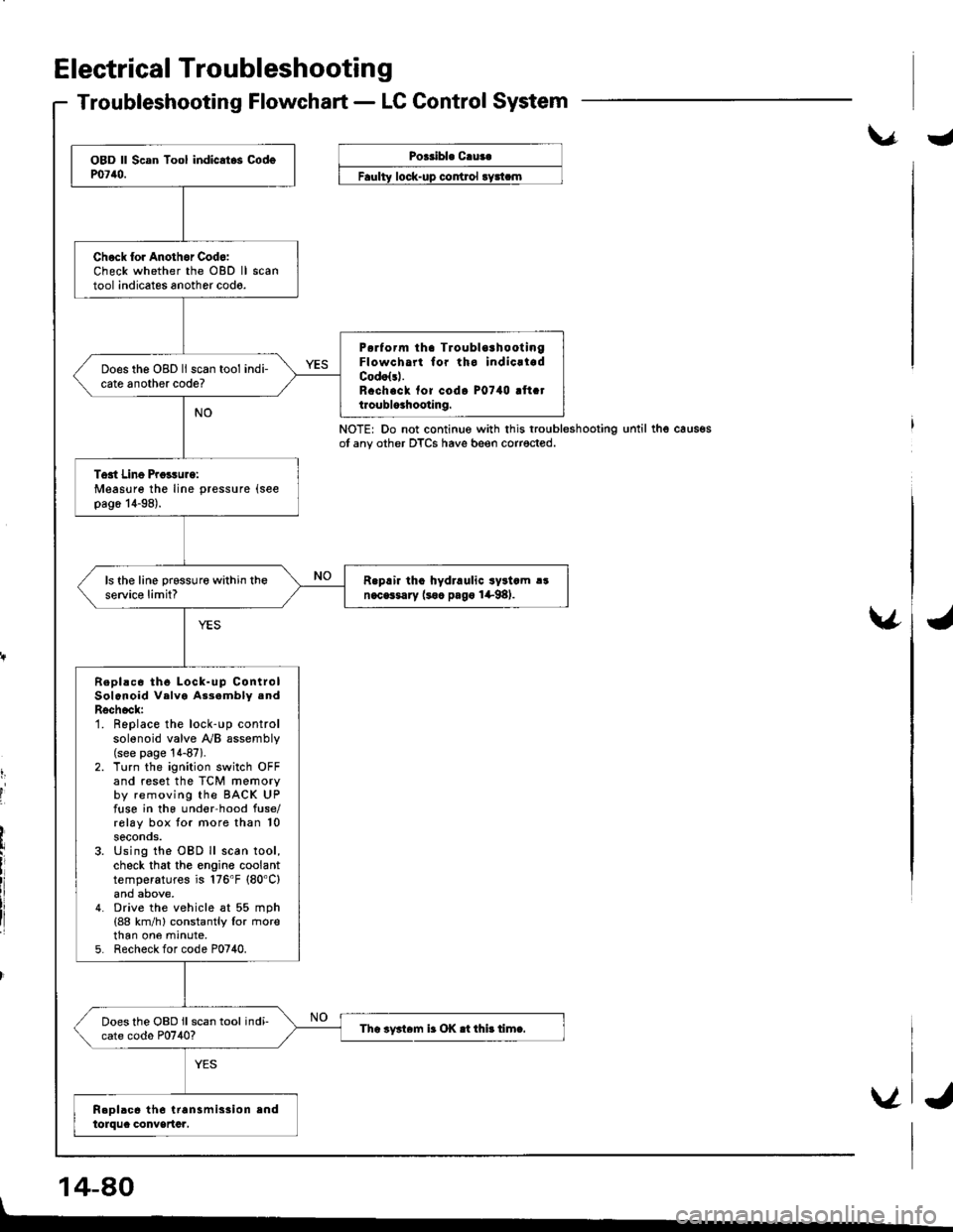
Electrical Troubleshootin g
Troubleshooting Flowchart - LC Control System
\.r.Poeribl. C.ua.
control
NOTE: Do not continue with this troubleshootingot any other DTCS have beeo corrected.until thg caus€s
v
t,
I
'I
14-80
Chock lor Anothor Cod6:Check whether the OBD lltool indicates another codo.
P6rform tha TroublorhootingFlowcha for tho indicrladCodolsl.R.ch.ck fof codo P0740 !ft.tt.oublo3hooting.
Does the OBD ll scan tool indi-cate another code?
Tost Line Proisurg:Measure the line pressure (see
pag6 14-98).
R.prir tho hydraulic syltcm !!n.cGsary (soc pago 1+98).ls the line prsssure within theservic€ limit?
Repl!c6 th6 Lock-up ControlSolenoid Velva As3ambly .ndRschock:1. Replace the lock-up controlsolenoid valve y'y'B assembly(see page '!4-87).
2. Turn the ignition switch OFFand reset the TCM memoryby removing the BACK UPfuse in the und€r-hood fuse/rolay box tor more than 10seconos.3. Using the OBD ll scan tool,check that the engine coolanttemperatures is 176'F (80'C)
4. Drive the vehicle at 55 mph(88 km/h) constantly lor rnorethan one mrnute,5. Recheck for code P0740.
Does the OBD ll scan tool indi-cate codo P0740?Tha iy3t6m ir OK .t thi! timc.
V
I
J
Page 498 of 1680
Electrical Troubleshooting
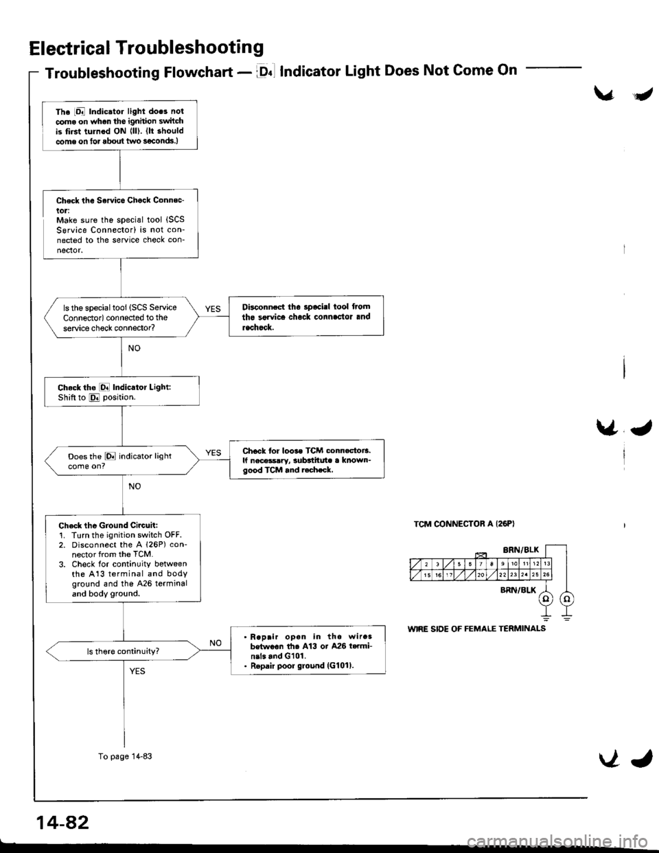
Troubleshooting Flowchart - lDnl IndicatorLight Does Not Come On
\/J
Check the Sowice Chock Connec-lol:Make sure the special tool {SCSSorvice Connector) is not con-nected to the service check con-
nector.
\/J
TCM CONNECTOR A I26PI
The iDal Indic.tor light does not
coma on whgn the ignhion switchis tirst tulnod ON {ll). (lt should
come on tor about two s€conds.)
Disconnect the 3pocisl tool from
tho sgrvice chock connlc'tor and
rachock.
ls the specialtool (SCS Service
Connedor) connected to the
service check connector?
Ch.ck tho [O! Indicator Light:Shiftto E position.
Chock tor loos. TCM conn.ctoi3.lf nece3s!ry, subttitute a known-good TCM and r.ch.ck,
Does the E indicator lightcome on?
Ch.ck the Ground Circuit:1. Turn the ignition switch OFF.2. Disconnect the A 126P) con-nector from the TCM.
3. Check lor continuity botweenthe A13 terminal and bodyground and tho 426 terminaland body ground.
Reprir opan in the wir.3betwoon th6 A13 or A26 t..mi-nil. and G101.Repair poor ground (G101).
To page 14-83VJ
14-a2
t-
Page 500 of 1680
Electrical Troubleshooting
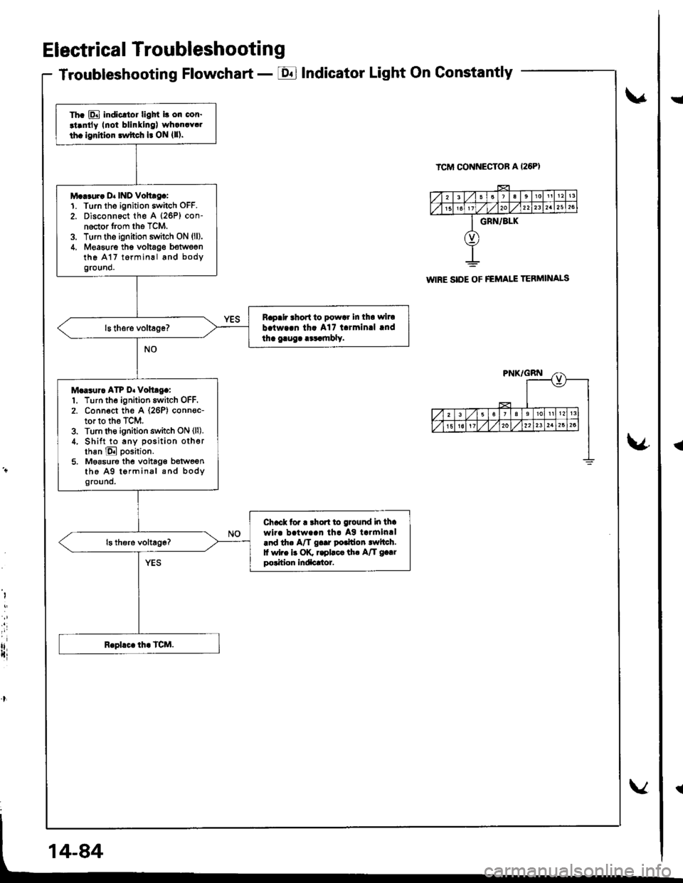
Troubleshooting Flowchart - EIndicator Light On Gonstantly
v
ICM CONNECTOR A I26PI
\4
I
i
rlIti
Th. E indicltor ligM i! on cor.
.t.ntly Inoi blinllng) wh.n.Y.l
th. lgrhior lwftch l. ON {ll).
M...ur. D. INO Vohtg.:1. Turn tho ignition switch OFF.
2. Disconnect th€ A (26P) con-noctor from the TCM.3. Turn the ignition switch ON (ll).
4. Measure thg voltag€ bstwegnthe A17 t6rminal and bodyground.
Rapalr ahort to powar In tha wiru
b.tw..n th. A17 l.rmin.l lnd
tha gaug. .cr.mbly.
M.a3ur. ATP D. voh.g.:1. Turn the ignition switch OFF.2. Conn€ct th€ A (26P) conn€c-tor to the TCM.3. Turn th€ ignition switch ON (ll).
4, Shift to any position otherthan E position.
5. Moasure the vohag€ b€tweenthe A9 tormin.l and bodyground.
Ch.ck tor r rhort to ground in thawir. b!tw..n th. Ag tarmin.l.nd th. A/T g..r potfion lwltch.f wi.e b OK r.pllca th. A/T g.|rpolition Indacrtor.
WIRE SIDE OF FEMAI.I TERMINALS
!
{
Page 649 of 1680
Steering
Componsnt Location
lndox
*Stooring Wheel
Removal ....
Disassombly/Ro8$.mbly
Disassombly ......
F08$€mbly
Powcr Stosring Gosrbox
R6moval
............................ 17-3
............. 17 -1
................ 17-16
............................. 17_25
17-30
17.31
.......17-21
Sy3tom DGcription
Fluid Flow Disgram
Steering Pump .............. 17-5
Stocring Goarbox ...17.8
Troublorhooting
Gonoral Troubleshooting .............................. 17.10
Noiso lnd Vibration ...... 17-1i[
Fluid Losk3
lnspoction
Installation
Powor Steering Hos6, Lino3
Roplacom€nt .................. 17.34
Powor Steoring Pump
RGplac6montlolpeqtion lnd Adiu3tm6nl
Stoo.ing Operation
Powor A$bi Chock
with v.hiclo Parked
Stcering Linkage 6nd Goarbox
Pump Bolt
17.18
17.18
17.19
17-20
17.35
t7-36
17 -37
r7-39
Inspoction
................... 17.41
Rack Guide Adiustmont ..........................-.-.-. 17 -21
Ffuid Rcplacemont ........17-21
Pump Prc&suro Chock ...,........................,..,..., 17 -22
Fluid Leakage Inrpection ............................... 17-23
Dissssembly
R€aEs€mbly
In3tallation........... 17_58
Ball Joint Boot Replacem.ni ........................ 17-61
17-U
17.49
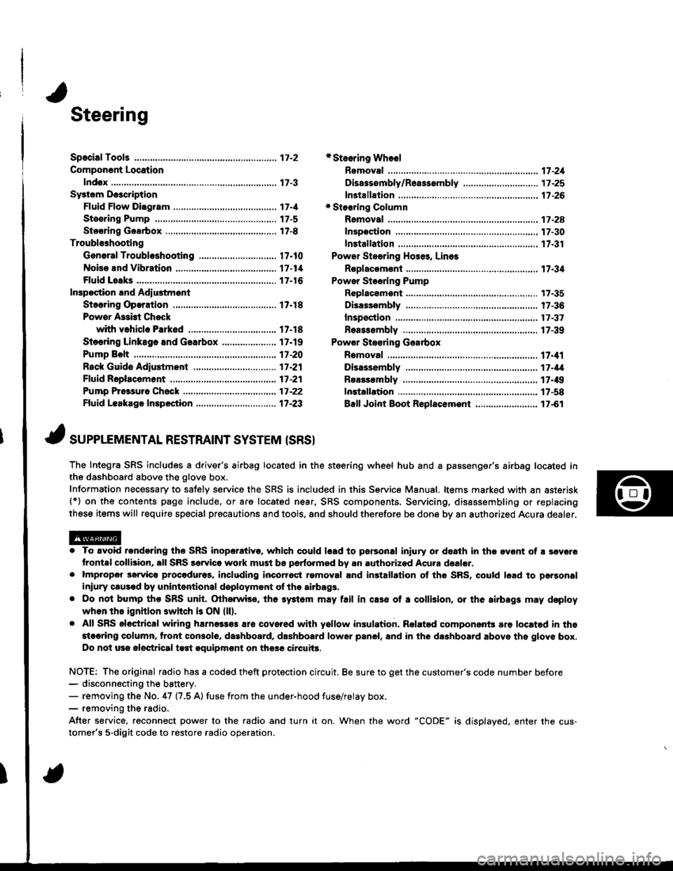
J ,urrar*TNTAL REsrRArNr sysrEM (sRsr
The Integra SRS includes a driver's airbag located in the steering wheel hub and a passenger's airbag located inthe dashboard above the glove box,
Information necessary to safely service the SRS is included in this Service Manual. ltems marked with an asterisk(*) on the contents page include, or are located near, SRS components. Servicing, dissssembling or replacing
these items will require special pr6cautions and tools, and should therefore be done by an authorized Acura dealer.
. To avoid rondoring ths SRS inoparstivo. which could |rad to parsonal iniury or doath in the ov€nt of ! sev6.o
trontal collision, all SRS sarvice work must be perto.med by an authorizod Acura dsalor.. lmpropor 3orvic€ procadures, including inco[6ql rgmoval and inrtallation of the SRS, could l6ad to pgrsonal
iniury clus€d by unintentional doployment of the airbags,. Do nol bump tho SRS unh, (Xherwise, th6 3ystom may fail in cas€ ol a collision, or the airbags may d€ploy
when ths ignition switch is ON {ll).. All SRS electrical wiring harness€s aro covered with yallow insulation. Related component3 are located in ths
stcaring column. tront con3ol6, dashboard, d.shbolrd lower panel, and in the dashboard above ths glove box.
Do not u3o electrical test oquipm€nt on the3e circuii3.
NOTE: The original radio has a coded theft protection circuit. Be sure to get the customer's code number before- disconn€cting the battery.- removing the No. 47 (7.5 A) fuse from the under-hood fuse/relay box,- removing the radio.
After service, reconnect power to the radio and turn it on. When the word "CODE" is displayed. enter the cus-
tomer's 5-digit code to restore radio operation.
Page 774 of 1680
Anti-lock Brake System {ABS}
Speciaf Tools ............... 19-24
Component Locations,...........,..,........... 19-25
Anti-lock Brake System (ABSI
Features/Construction ....................... 19-2G
Circuit Diagram ........... 19-30
ABS Control Unit Terminal
Arrangement ........... 19-32
Troubleshooting Precautions ................ 1g-35
Diagnostic Trouble Code (DTC)
DTC Indication (SCS Mode) ............... t9-37
DTC Erasure {MES Mode) .................. 19-38
b Troubleshooting Index ...................... 19-39- Troubleshooting
ABS Indicator Does Not
Come On .............. 19-40
ABS Indicator Does Not
Go Off .............. ..... 19-42
DTC 11, 13, 15. 17:
Wheel Sensor (Open/Short to Body
Ground/Short to Power) ............... l9-44
DTC 12. 14, 16, 18:
Wheel Sensor (Electrical Noise/
Intermittent Interruption) ..........,.. 19-45
DTC21 -24:
Pulser ...,.......... ..... 19-46
DTC 31 - 38:
Solenoid .............. 19-47
DTC 41 - 44:
Wheel Lock .......... 19-50
DTC 51:
Motor Lock .......... 19-51
DTC 52:
Motor Stuck OFF ...................,........ 19-52
DTC 53:
Motor Stuck ON ............................. 19-55
DTC 54:
Fail-safe Relay ................................ t9-57
DTC 61.62:
lgnition Voltage ............................. 19-59
DTC 71:
Different Diameter Tire .................. 1 9-60
DTC 81:
Gentral Processing
Unit {CPU} ............ 19-60
Modulator Unit
Bemoval/lnstallation ......................... 19-61
ABS Control Unit
Replacement ............ 19-62
Pulsers/Wheel Sensors
Inspection ................ 19-62
Wheel Sensors
Replacement .,.......... 19-63
Page 790 of 1680
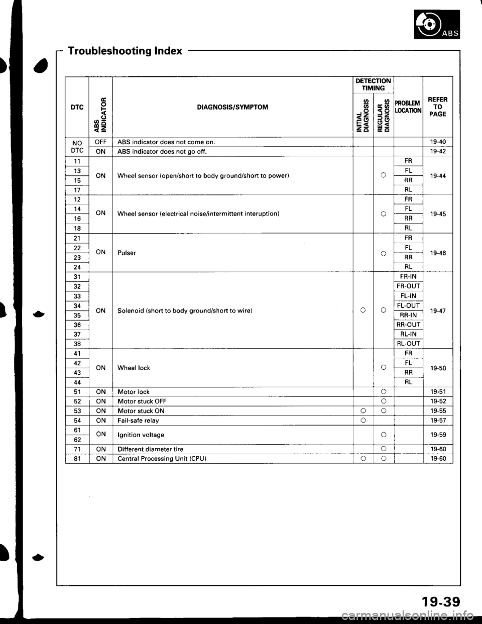
DTC
E
F
o^
e=
DIAGNOSIS/SYMPTOM
DETECTIONTIMING
PROBIEMLOCAIION
REFERTOPAGE
Io-<1
E
Y<
NODTC
OFFABS indicator does not come on.19-40
ONABS indicator does not go off.19-42
tl
ONWheel sensor (open/short to body ground/shon to power)o19-44t3FL
RR
17RL
12
ONWheel sensor (electrical noise/interminent interuption)o
FR
19-4514FL
16RR
18RL
ONPulsero
FR
19'4622
RR
24RL
ONSolenoid (short to body ground/shon to wire)oo
FR-IN
19-47
FR.OUT
33FL-IN
34FL-OUT
RR-IN
RR-OUT
37RL.IN
38RL-OUT
41
ONWheel locko19-5042FL
43RR
44RL
ONMotor locko19-51
52ONMotor stuck OFFo19-52
53ONMotor stuck ONoo19-55
54ONFailsafe relayo19-57
61ONlgnition voltageo19-59
71ONDifferent diameter tireo19-60
81ONCentral Processing Unit (CPU)oo19-60
Troubleshooting Index
19-39
Page 796 of 1680
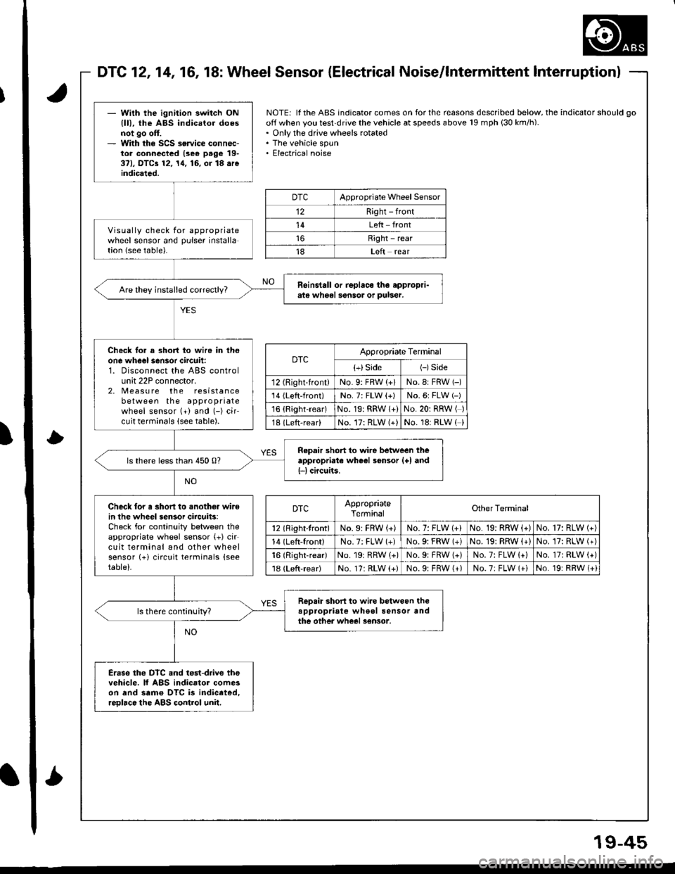
l
DTC121416, 18: Wheel Sensor {Electrical Noise/lntermittent lnterruptionl
- Wilh the ignition switch ONlll), the ABS indicator doesnot go off.- With the SCS service connec-tor connectcd (3e6 page 19-37), DTCa 12, 14, 16, or 18.reindicated.
Visually check for appropriatewheel sensor and pulser installation (see table).
Reinstall or replace th6 eppropri-ats wh6el sensor or puber.
Ch€ck lor a short to wire in thoone wheel s6nsor circuit:1. Disconnect the ABS controlunit 22P connector.2. Measu re the resistancebetween the appropriatewheel sensor (+) and (-) circuit terminals (see table).
Repair short to wire between theappropriate wheel sensor {+) and{-l circuits.ls there less than 450 0?
Check lor a short to .nother wirein lhe wheel sensor circuits:Check for continuity between theappropriate wheel sensor (+) circuit terminal and other wheelsensor (+i circuit terminals (see
table)-
R€psir short to wire between theappropriale wheol sensor andthe other wheel sensor.ls there continuity?
Eraso the DTC and test-drive thevehicle. lf ABS indicator comeson and same OTC is indiceted,reDlace the ABS control unil.
NOTE: ll the ABS indicator comes on for the reasons described below, the indicator should go
off when you test'drive the vehicle at speeds above 19 mph 130 km/h).. Only the drive wheels rotated. The vehicle spun. Electrical noise
DTCAppropriate Wheel Sensor
12Right - front
14Left front
Right - rear
18Left rear
DTCAppropriate Terminal
{+}Side(-)Side
12 (Right-front)No. 9: FRW (+)No.8: FRW (-)
'14 {Left-front)No. 7: FLW {+)No.6: FLW (-)'16 {Right-rear)No. 19: RRW 1+)No.20: RRW ( )
18 (Left-rear)No. 17: RLW (+)No. 18: RLW ( )
DTCAppropriateTerminalOther Terminal
12 (Right-tront)No.9: FBW (+)No. 7: FLW 1+)No. 19: RRW (+)No. 17: RLW (+)
14 (Left-front)No.7: FLW (+)No.9i FRW (+)No. 19: RRW (+)No. 17: RLW (+)
16 (Right-rear)No. 19r RRW {+)No.9: FRW (+)No. 7: FLW 1+)No.17: RLW (+)'18 (Left-rear)No. 17: RLW (+)No.9: FRW (+)No.7; FLW (+iNo. 19: RRW (+i
'
L
19-45