electrical ACURA INTEGRA 1998 Service Manual PDF
[x] Cancel search | Manufacturer: ACURA, Model Year: 1998, Model line: INTEGRA, Model: ACURA INTEGRA 1998Pages: 1680, PDF Size: 53.14 MB
Page 1539 of 1680
Power Windows (conrd)
- How the Circuit Works
CAUTION: You could iniure your arms, hands,
or fingers if you unintentionally switch the
driver's window to "automatic down,' while
working in that door with the power on. Discon-
nect the window switch connector or the battery
when working in the driver's door.
System Description
The operation of the power windows is controlled by
the main switch in the power window masler switch.
When the main switch is in OFF, only the driver's
door window can be opened or closed. With the main
switch ON, all windows can be opened or closed
either by switches in the master panel, or switches in
the doors. The driver's window switch also has an
automatic down mode which is tumed on by pushing
the switch down to its second position.
The power windows are driven by reversible motors.
Each motor is protected by a built-in circuit breaker.
lf the window switch is held on too long (with the
window obstructed, or after the window is fully up or
down), the circuit breaker opens the circuit. The
circuit breaker resels automaticallV as it cools.
Driver's Window
With the ignition switch in ON (tt), vottage isprovided to the coil ol the power window relay
through fuse 24. The contacts of the power window
relay close, and voltage is applied to the driver's
switch. When you push the power window master
switch to Uq voltage is applied to the driver's power
window motor. (The motor's ground path is backthrough the power window master switch.) The
driver's window motor then drives the window uo.
When you push the switch to DOWN, voltage ls
applied in the opposite direction and the motor
drives the window down.
Automatic Down (Driver's Window)
With the ignition switch in ON (tl), vottage is applied
to the coil of the power window relay. The contacts
of the power window relay close and voltage is
applied to the power window master switch. When
you push the driver's switch to the AUTO DOWN
position, voltage is applied through the drivels
switch to the driver's window motor. The control unit
receives pulses at the pulser input while the motor
is running. When the window is fully down, the
motor stops, and pulses are no longer generated by
the pulser. This is sensed by the control unit at thepulsBr input, and voltage is no longer applied to the
driver's window motor.
Passenger Windows
With the ignition switch in ON (tt), vottage is apptied
to the coil of the power window relay through fuse
24. The contacts of the power window relay then
close, applying voltage to the individual window
switches and the power window master switch. With
the master panel main switch ON, the passenger
windows can be operated from the individual
window switches or from the master Danel switches.
When you push the front passenger's window
switch to UR voltage is applied to the front
passenger's window motor. (The motor is grounded
through the contacts in the front passenger's window
switch and the power window master switch.) The
wndow moves up as long as you hold the switch in
lhe UP position. lf you push the switch to DOWN,
voltage is applied in the opposite direction io the
front passenger's window motor, and the window
moves down as long as you hold the switch in the
DOWN position. The window switches in the other
doors operate similarly.
When you push the front passenger's switch in the
master panel to UP, voltage is applied through the
front passengeas window switch contacts to the
front passenger's window motor (The motor is
grounded through the contacts in the front
passenger's window switch and the power window
master switch.) The window moves up as long asyou hold the switch in the UP position. lf you push
the switch to DOWN, voltage is applied in the
opposite direction to the front passenger's window
motor, and the window moves down as long as you
hold the switch in the DOWN position. The otherpassenger window switches in the master panel
operate similarly.
Refer to the Service Manual (Section 23, Electrical)
for specific tests or troubleshooting procedures.
120-6
Page 1541 of 1680
- How The Circuit Wo
With the ignition switch ON (ll), voltage is applied
through fuse 24 to the coil of the moonroof relay.
The moonroof relay energizes and voltage is
applied from fuse 49 through the closed contacts of
the moonroof relay to the moonroof switch.
Open Operation
When you push the moonroof switch to the OPEN
position, voltage is applied to the moonroof motor.
The moonroot motor is grounded through the
CLOSE contacts of the moonroof switch, and the
motor runs to open the moonroof
Close Operation
When you push moonroof switch to the CLOSE
position, voltage is applied to the moonroof motor.
The moontoof motor is grounded through the OPEN
contacts of the moonroof switch, and the motor runs
to close the moonroof.
Refer to the Service Manual (Section 23, Electrical)
for specific tests or troubleshooting procedures.
122-1
Page 1547 of 1680
- How the Circuit Works
The immobilizer system is designed to prevent the
car f rom being started without the owner's ignition
key. lf an attempt is made to start the car without
the correct key, the immobilizer system will disable
the car's fuel supply.
The immobilizer system consists of the ignition key,
immobilizer receiver unit, immobilizer indicator
light, PGM-FI main relay, fuel pump, and the PCM
or ECM.
With the ignition switch in ON (ll) or START (lll), the
immobilizer receiver unit and the PCM or ECM
receive an "ignition on" signal through fuse 44 and
the PGM-FI main relay. The PCM or ECM then
sends power to the ignition key transponder through
the immobilizer receiver unit. The transponder then
sends a coded signal back to the PCM or ECM
through the receiver unit. lf the signal is correct, the
PCM or ECM will energize the car's fuel supply
system by grounding the PGM-FI main relay. The
immobilizer indicator light flashes a code to indicate
that the correct key has been inserted. lf the
ignition key signal is not correct, the PCM or ECM
will not energize the car's fuel supply system by not
grounding the PGM-Fl main relay. The immobilizer
indicator light then flashes a code to indicate that an
incorrect key has been inserted.
Refer to the Service Manual (Section 23,
Body Electrical) for specific tests and
troubleshooting procedures.
132-1
Page 1557 of 1680
lnterlock System
- How the Circuit Works
Key Interlock
Battery voltage is supplied at all times through f use
33 to the key interlock switch. When the key is in
the ignition, battery voltage is supplied to the key
intedock solenoid and the key interlock circuit in the
interlock control unit. When the A/T gear position
switch is in PABK, ground is provided to the key
interlock circuit. This removes ground from the
interlock solenoid, the solenoid is deenergized, and
the key can be removed from the ignition.
Shift Position Interlock
Battery voltage is supplied at all times lrom fuse 52
to the brake switch. With the ignition in ON (ll) or
START (lll), battery voltage is supplied through luse
25 to the shift lock solenoid. When you push the
brake pedal, battery voltage is applied through the
GRN/VVHT wire to the transmission ('98-�99 models)
or powertrain ('00 model) control module (TCM or
PCM). lf, at the same time, you do not push the
accelerator pedal, a low voltage signal is sent
through the RED/BLK wire to the TCM or PCM. The
TCM or PCM then applies voltage through the
WHT/RED wire to the shift lock circuit in the
interlock control unit. lf the A,/T gear position switch
is in the PARK position, the shift lock circuit
provides ground to the shift lock solenoid. The
solenoid is then energized, and the shift lever can
be moved from the PARK Dosition.
Refer to the Service Manual (Section 23, Electrical)
for specific tests or troubleshooting procedures.
138-2
Page 1560 of 1680
Power Mirrors
- How the Gircuit Works
The two outside mirrors are controlled by the power
minor switch. Each mirror has two reversible
motors: one motor moves the mirror uo and down
and the other motor moves the mirror left and right.
The oower mirror switch contains three switches lo
control mirror direction, and two switches to select
the left or right mirror. With the ignition in ON (ll),
battery voltage is supplied to the power mirror
switch. The mirror selector switch directs voltage
from two of the direction switches to either the left
or the right minor. Each direction switch is used for
more than one function.
Mirror Up Operation
With the power mirror switch in the up position,
switch 1 is moved to the A oosition. Switch 1
applies battery voltage to both the left and right
power mirror up/down motors. lf the mirror selector
switch is in the left position, the left up/down motor
is grounded through the mirror selector switch and
switch 2 in the B position to G501 (Sedan) or G502
(Hatchback). lf the right mirror up/down motor is
selected il is also grounded through switch 2 in the
B position.
Mirror Down Operation
With the power mirror switch in the down position,
switches 2 and 3 are moved to the A position.
Switch 2 applies battery voltage to the left or right
power mirror up/down motor as determined by the
mirror selector switch. The selected mirror motor is
grounded through switch I in the B position to G501
(Sedan) or G502 (Hatchback). When switch 2 is
moved to position A, it also applies battery voltage
to the selected mirror lefyright motor. With switch 3
in the A position, battery voltage is supplied to both
sides of the leruright motor so it does not move.
Mirror Left Operation
With the power mirror switch in the left position,
switches 1 and ? ate moved to the A oosition.
Switch 2 applies battery voltage to the left or right
power mirror lefvright motor as determined by the
mirror selector switch. The selected mirror motor is
grounded through switch 3 in the B position to G501
(Sedan) or G502 (Hatchback). When switch 2 is
moved to position A, it also applies battery voltage
to the selected mirror up/down molor. With switch 1
in the A position, battery voltage is supplied to both
sides of the uD/down motor so it does not move.
Mirror Right Operation
With the power mirror switch in the right position,
switch 3 is moved to the A position. Switch 3
applies battery voltage through the mirror selector
switch to the left or right lefvright motor. The
motor is grounded through the mirror selector
switch and switch 2 in the B oosition to G501
(Sedan) or G502 (Hatchback).
Refer to the Service Manual (Section 23, Electrical)
for specific tests or troubleshooting procedures.
141-2
Page 1655 of 1680
ng
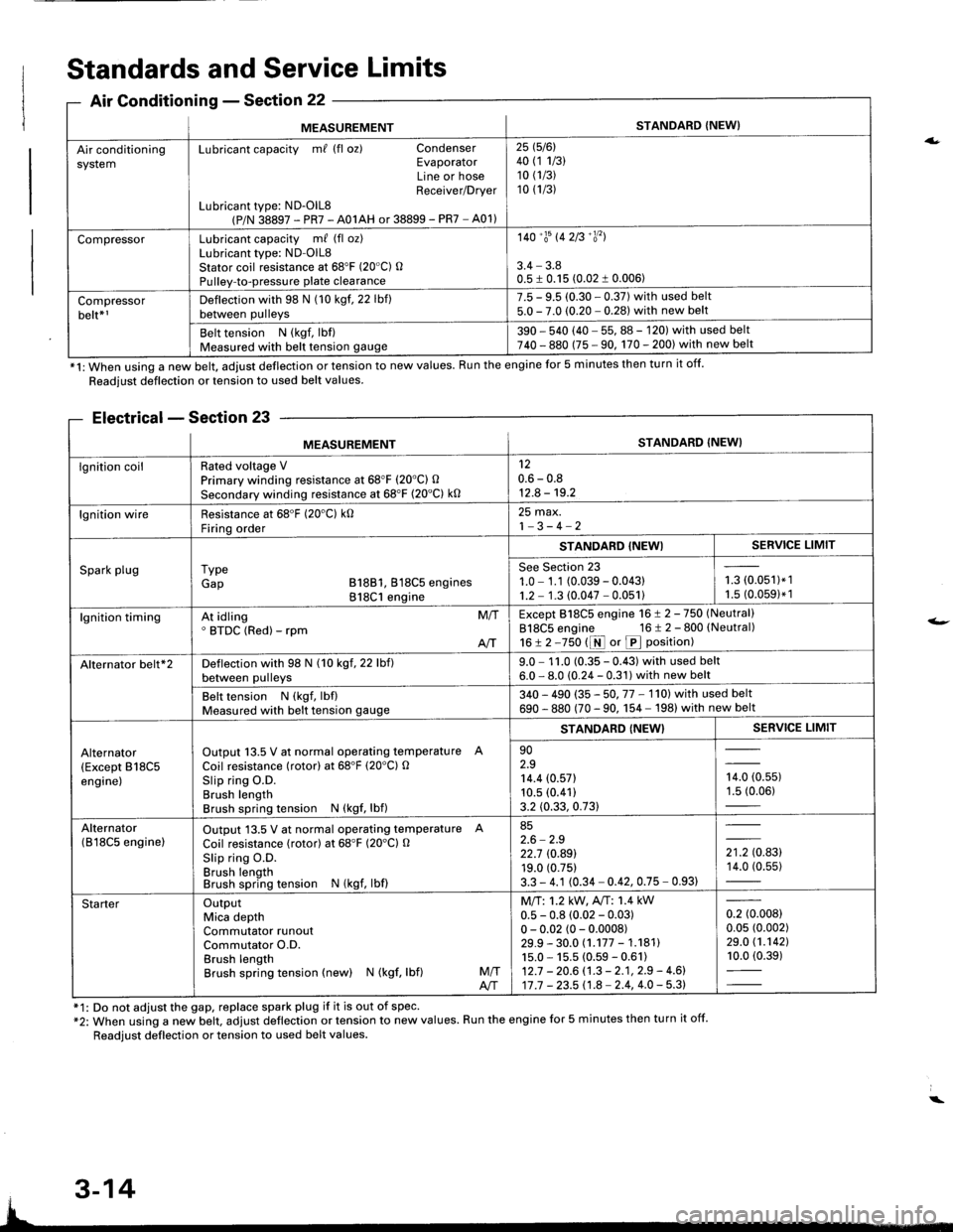
MEASUREMENTSTANDARD {NEW}
Air conditioningsystemLubricant capacity m/ (fl oz) CondenserEvaporatorLine or hoseReceiver/Drver
Lubricant type: ND-OlL8(P/N 38897 - PR7 - A01AH or 38899 - PR7 - A01)
25 1516l40 (1 1/3)10 (1/3)
10 (1/3)
CompressorLubricant capacity m/ (fl oz)Lubricant type: ND-OlL8Stator coil resistance at 68'F (20"C) OPulley-to-pressure plate clearance
140'�trs 142B'�y'�l
3.4 - 3.80.5 I 0.15 (0.02 1 0.006)
Compressorbelt*rDeflection with 98 N (10 kgf. 22 lbf)between pulleys
7.5 - 9.5 (0.30 - 0.37) with used belt5.0 - 7.0 (0.20 - 0.281 with new belt
Belt tension N (kgf, lbf)Measured with belt tension gauge390 - 540 (40 - 55, 88 - 120) with used belt740 - 880 (75 - 90, 170 - 200) with new belt
*1: When using a new belt, adjust deflection or tension to new values. Run the engine for 5 minutes then turn it off.
Standards and Service Limits
Air Conditionins - Section 22
Readjust deflection or tension to used belt values.
Electrical - Section 23
f1: Do not adjust the gap, replace spark plug if it is out of spec'*2: When using a new belt. adjust deflection or tension to new values. Run the engine for 5 minutes then turn it off.
Readjust deflection or tension to used belt values.
a.
t-
MEASUREMENTSTANDARD (NEW}
lgnition coilRated voltage VPrimary winding resistance at 68"F (20'C) O
Secondary winding resistance at 68'F (20"C) k0
120.6 - 0.812.8 - 19.2
lgnition wireResistance at 68'F (20'C) k0Firinq order
25 max.1-3-4-2
Spark plugI ypeGap B18B1, 818C5 engines818C1 engine
STANDABD {NEWISERVICE LIMIT
See Section 231.0 - 1.1 (0.039 - 0.04311.2 - 1.3 (0.047 - 0.051)i-= roru',t.',1.5 (0.0591* 1
lgnition timingAt idling' BTDC (Red) - rpmM/T
AIT
Except 818C5 engine 16 ! 2 -750 (Neutral)
818C5 engine 16 t 2 - 800 (Neutral)
16!2-750 t1r{ or p position)
Alternator belt*2Deflection with 98 N (10 kgf, 22 lbf)between pulleys9.0 - 1 1.0 (0.35 - 0.43) with used belt6.0 - 8.0 (0.24 - 0.31) with new belt
Belt tension N (kgf, lbflMeasured with belt tension gauge340 - 490 (35 - 50. 77 - 1'l0l with used belt
690 - 880 (70 - 90. 1 54 - 198) with new belt
Alternator(Except B18C5engine)
Output 13.5 V at normal operating temperature A
Coil resistance (rotor) at 68'F (20'C) OSlip ring O.D.Brush lengthBrush spring tension N (kgf, lbf)
STANDARD {NEW}SERVICE LIMIT
902.914.4 (0.571
10.5 (0.41)
3.2 (0.33, 0.73)
,0, to.uur1.5 (0.06)
Alternator(B l8C5 enginelOutput 13.5 V at normal operating temperature A
Coil resistance (rotor) at 68"F (20'Cl O
Slip ring O.D.Brush lengthBrush spring tension N (kgf, lbf)
852.6 - 2.922.7 rc.89119.0 (0.75)
3.3 - 4.1 (0.34 - 0.42, 0.75 - 0.93)
',to.tg14.0 (0.55)
StarterOutputMica depthCommutator runoutCommutator O.D.Brush lengthBrush spring tension (new) N (kgf, lbf)M/TA/T
Mll:1.2 kW, A"rT: 1.4 kW0.5 - 0.8 (0.02 - 0.03)0 - 0.02 (0 - 0.0008)29.9 - 30.0 (.177 - 1.18111s.0 - 15.5 (0.59 - 0.61)12.7 - 20.6 (.3 - 2.1, 2.9 - 4.6)17 .7 - 23.5 11.8 - 2.4, 4.0 - 5.3)
0.2 (0.008)
0.05 (0.002)
29.0 (1.1421
10.0 (0.39)
3-14
Page 1658 of 1680

:/
*1: RS*2: LS, GS, GS.R, TYPE R*3: RS+4: TYPE R*5: Except high mount brake light installed in rear spoirer.
ITEMMETRICENGLISHNOTES
WHEELALIGNMENTCamber Front TYPE RAll Except ryPE RRearCaster FrontTotal Toe FrontRear
-0"30'_0"10,_0"45'
1"10'omm I oinIn 2 mm I In 1/16 inBRAKE SYSTEMType Front
RearPad Surface Area FrontRearParking Brake Type
Power-assisted self-adjustingventilated discPower-assisted self-adlusting sol id disc50.0 cm2 x 2 | 7.75 sq in x 221.0 cm, x 2 | a.ZO sq in x 2Mechanical actuating, rear two wheel brakesTIRESize Front and rear
Spare Tire
P195/60R14 85H*1P195/55R15 84V*2T115t0D14*3T125/70D14*2T125n0D15*4
ELECTRICALBatteryStarterAlternatorFusesIn Under-dash Fuse/Relay BoxIn Under-hood Fuse/Relay Box
In Under-hood ABS Fuse/Relay BoxHeadlights
Front Side Marker LightsFront Turn Signal/Parking LightsRear Turn Signal LightsBrake/TaillightsHigh Mount Brake Light*5Rear Side Marker LightsBack-up LightsLicense Plate LightsCeiling LightsCargo Area Lights (3-door)Trunk Lights (4-door)SpotlightsGlove Box LightGauge LightsIndicator Lightslllumination and Pilot LightsHeater lllumination Lights
HighLow
12 V _ 36 AH/5 HR12V -1.2/'t.4kW
12V-90A/85A
7.5 A, 10 A, 15 A, 20 A, 30 A7.5 A. 10 A, 15 A, 20 A, 30 A, 40 A50A,100A10A,15A,20A,40A12V-60W(H83)12V -51 W (HB4)12V-3CP12V _3213 CP12V _32 CP12V-3213CP't2v -21 W12 V - 3 CP12V -32CP
12V_8W12V-5W12V-3.4W12V-3.4W12V_5W12V-3.4W12V-3.4W12 V - 0.84 W, 0.91 W, 1.12W, 1.4W, 3 W12 V - 0.84 W, 0.91 W, 1.4 W, LED12V-1.4W
SAE 168SAE 1157SAE 1156SAE 1157SAE 7440SAE 168SAE 1156
3-17
Page 1670 of 1680
Radiator
Engine Goolant Refilling and Bleeding
CAUTION: When pouring engine coolant, be sure to
shut the relay box lid and not to let coolant spill on the
electrical parts or the paint. lf any coolant spills, rinse it
off immediately.
1. Slide the heater temperature control lever to maxi-
mum heat.
Make sure the engine and radiator are cool to the
touch.
2. Remove the radiator caD.
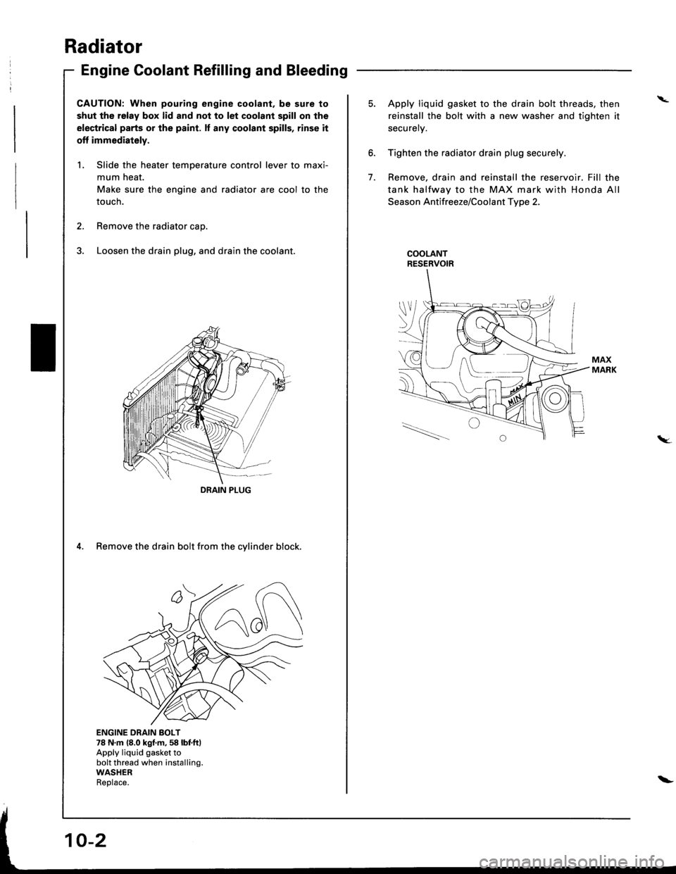
3. Loosen the drain plug, and drain the coolant.
4. Remove the drain bolt from the cylinder block.
ENGINE DRAIN BOLT78 N.m (8.0 kgf.m,58 lbf.ftlApply liquid gasket tobolt thread when installing.WASHERReolace.
DRAIN PIUG
I \.--
\_-l - I
\
6.
7.
5. Apply liquid gasket to the drain bolt threads, then
reinstall the bolt with a new washer and tighten it
securely.
Tighten the radiator drain plug securely.
Remove, drain and reinstall the reservoir. Fill the
tank halfway to the MAX mark with Honda All
Season Antifreeze/Coolant Type 2.
COOLANTRESERVOIR
tW.
\-