electrical ACURA INTEGRA 1998 Service User Guide
[x] Cancel search | Manufacturer: ACURA, Model Year: 1998, Model line: INTEGRA, Model: ACURA INTEGRA 1998Pages: 1680, PDF Size: 53.14 MB
Page 244 of 1680
I
t
h,,l,!
il
Troubleshooting
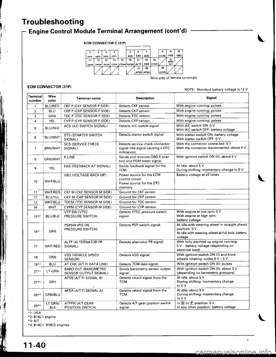
ECM CONNECTOR {31P)
Engine Control Module Terminal Arrangement (cont'd)
ECM CONNECTOR C {31P)
235srsscs1112t31515t71A19
2A
Wire side of lemale terminals
NOTE: Standard battery voltage is 12 V.
TerminalnumbercolorTerminal namoD6scriptionSignal
1BLU/REDCKF P (CKF SENSOR P SIDE)Detects CKF sensor.With engine running: pulses
28LUCKP P (CKP SENSOR P SIDE)Detects CKP sensor.With engine running: pulses
3GRNTDC P {TDC SENSOR P SIDE)Detects TDC sensor,With engine running: pulses
YELCYP P (CYP SENSOR P SIDE)Detects CYP sensor,With engine running: pulses
5BLU/REDACS (AJC SWITCH SIGNAL)Detects A,/C switch signal.With A,/C switch ON: 0 VWith A,/C switch OFF: battery voltage
6BLUA/VHTSTS (STARTEB SWITCHSIGNAL)
Detects starter switch signal.With staner switch ON: battery voltageWith starter switch OFF: 0 V
7BRN,AiVHTSCS (SERVICE CHECKSIGNAL)Detects service check connectorsignal (the signalcausing a DTC;ndication).
With the co n nector con nected: 0 VWath the connector disconnected: about 5 V
8GRNAVHTK LINESends and receives OBD ll scantool and PGM tester signal.With ignition switch ON (ll): about 5 V
9YELFAS lFEEDBACK AT SIGNAL)Sends feedback signal for theTCM,At idle: about 5 VDuring shifting: momenlary change to 0 V
10WHT/BLU
VBU (VOLTAGE BACK UP)Power source for the ECMcontrolcircuit,Power source for the DTC
Battery voltage at all times
t1WHT/REDCKF M (CKF SENSOR I\4 SIDE)Ground for CKF sensor.
12BLUI/E LCKP M (CKP SENSOR M SIDE)Ground for CKP sensor.
WHT/BLUTDCM (TDC SENSOR M SIDE)Ground tor TDC sensor.
14CYPM (CYP SENSOR M SIDE)Ground for CYP sensor.
15*.BLU/BLKVTP SW (VTEC
PRESSUFE SWITCH)Detects VTEC pressure switchsr9nal.
With engine at low rpm:0 VWith engine at high rpmlbattery voltaqe
161,GRN
PSPSW (P/S OILPRESSURE SWITCH)Derecls PSP switch signal.At idle with steering wheel in straight aheadpositioni 0 VAt idle with steering wheelat full lock: batteryvoltage
17WHT/REDALTF (ALTERNATOR FRSIGNAL)Detects alternator FR signal.With fully warmed up engine running:0 V battery voltage (depending onelectrical load)
18ORNVSS (VEHICLE SPEEDSENSORiDetects VSS signal.With ignition switch ON (ll) and lrontwheels rotating: cycles 0 V- 5 V
19*3BLUAT CHK (A/T FI DATA LINE)Detects TCM data signal.With ignition switch ON (ll)i pulses
21*LT GRNBARO OUT (SAROMETRIC
SENSOR OUTPUT S!GNAL)Sends barometric sensor outputsrgnal,With ignition switch ON (ll): about 3 V(depending on barometric pressure)
27 x3GRYAFSB (A"/T FI SIGNAL B)Detects retard signal from theTCM,At idle: about 5 VDuring shifting: momentary changeto0V
28+1GRN/8LUA+SA (A/T FI SIGNAL A)Detects retard signal from theTCM.At idle: about 5 VDuring shifting: momentarV changeto0V
29+3LT GRN/BLKATPPN (A/T GEARPOSITION SWITCH)Detects A,/T gear position switchsrgnal-In E orE positionr 0VIn anv other position: battery voltage
*1: USA*2:818C1 engine*3: A/T*4: 818C1, 818C5 engines
Page 248 of 1680
Troubleshooting
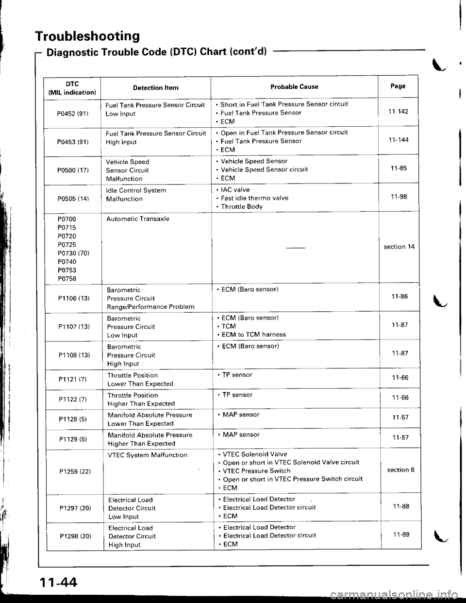
Diagnostic Trouble Code (DTCI Chart (cont'd)
L
DTC
(MlL indication)Detection ltemProbable CausePage
P0452 (91)FuelTank Pressure Sensor Circuit
Low lnput
Short in Fuel Tank Pressure Sensor circuit
Fuei Tank Pressure Sensor
ECM
11 142
P0453 (91)Fuel Tank Pressure Sensor Circuit
High Input
Open in Fuel Tank Pressure Sensor circuit
Fuel Tank Pressure Sensor
ECrVI
11-144
P0500 {17}
Vehicle Speed
Sensor Circuit
Malfunction
Vehicle Speed Sensor
Vehicle Speed Sensor circuit
ECM
11-85
P0505 (14)ldle Control System
Malfunction
IAC valve
Fast idle thermo valve
Th rottle Body
'11-98
P0700
P0715
P0120
P0125
P0730 (70)
P0740
P0753
P0758
Automatic Transaxle
section'14
Pl106 (13iBarometric
Pressure Circuit
Range/Performance Problem
. ECM (Baro sensor)1'l -86
P1107 ('�]3)Barometric
Pressure Circuit
Low lnput
ECM (Baro sensor)
TCM
ECM to TCM harness
11-87
P1'108 (13)Ba ro metric
Pressure Circuit
High Input
ECM (Baro sensor)11-41
P1121 \11Throttle Position
Lower Than Expected
. TP sensor
P112211JThrottle Position
H igher Than Expected
'TP sensor
P1 '�t 28 (5)Manifold Absolute Pressure
Lower Than Expected
. MAP sensor11,57
P1129 (5)Manilold Absolute Pressure
Higher Than Expected
. MAP sensor11-57
P1259 \22)
VTEC System MalfunctionVTEC Solenoid Valve
Open or short in VTEC Solenoid Valve circuit
VTEC Pressure Switch
Open or short in VTEC Pressure Switch circuit
ECM
section 6
P1297 (20)Electrical Load
Detector Circuit
Low Input
Electrical Load Detector
Electrical Load Detector circuit
ECM
11-88
P1298 (20)Electrical Load
Detector Circuit
Hig h Input
Electrical Load Delector
Electrical Load Detector circuit
ECM
11-89
-44
Page 251 of 1680
How to Read Flowcharts
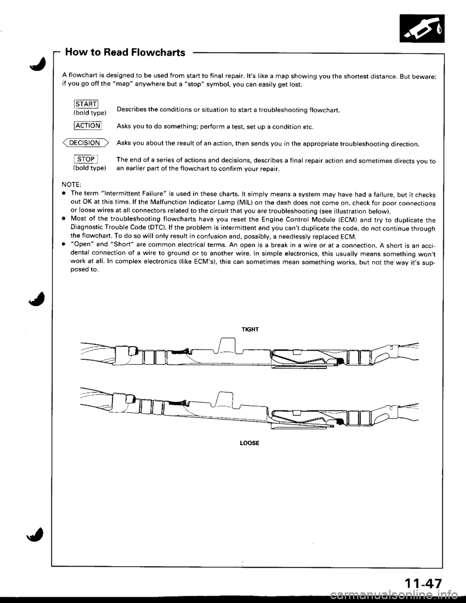
A flowchart is designed to be used from start to final repair. lt's like a map showing you the shone$ distance. But beware:if you go off the "map" anywhere but a "stop" symbol, you can easily get lost.
FTARN(bold type)
FcroNl
@>
sroFl
(bold type)
NOTE:
. The term "lntermittent Failure" is used in these chans. lt simply means a system may have had a failure, but it checksout OK at this time. lf the Malfunction lndicator Lamp (MlL) on the dash does not come on, check for poor connectionsor loose wires at all connectors related to the circuit that you are troubleshooting (see illustration below).. Most of the troubleshooting flowcharts have you reset the Engine Control Module (ECM) and try to duplicate theDiagnostic Trouble Code (DTC). lf the problem is intermittent and you can't duplicate the code, do not continue throughthe flowchart. To do so will only result in confusion and, possibly, a needlessly replaced ECM.. "Open" and "Short" are common electrical terms. An open is a break in a wire or at a connection. A short is an acci-dental connection of a wire to ground or to another wire. In simple electronics, this usually means something won,twork at all. In complex electronics (like ECM's), this can sometimes mean something works, but not the way rr s sup-posed 10.
Describes the conditions or situation to start a troubleshootinq flowchart
Asks you to do something; perform a test, set up a condition etc.
Asks you about the result of an action, then sends you in the appropriate troubleshooting direction.
The end of a series of actions and decisions, describes a final repair action and sometimes direcls you toan earlier part of the flowchart to confirm your repair.
11-47
Page 258 of 1680
J
i
'ilPGM-FI System
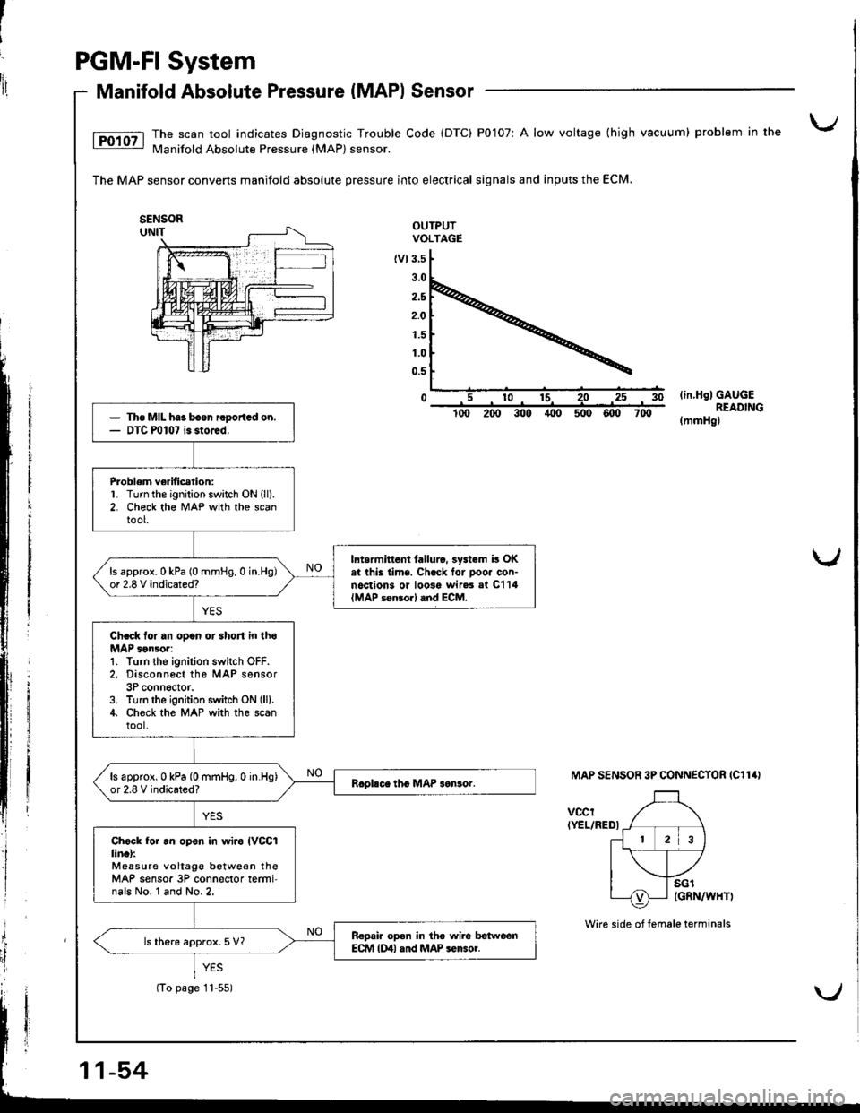
Manifold Absolute Pressure (MAPI Sensor
The scan tool indicates Diagnostic Trouble Code (DTC) P0107r A low voltage (high vacuum) problem in the
N4anifold Absolute Pressure (MAP) sensor.
The MAP sensor converts manifold absolute pressure into electrical signals and inputs the ECM.
OUTPUTVOLTAGE
(vt3.5
2.5
2.O
1.5
1.0
0.5
0lin.HglGAUGEREADING(mmHgl
MAP SENSOR 3P CONNECTOR IC114I
vccrIYEL/REDI
i
Ii
{
il
The MIL haa baen raportGd on.DTC P0107 is storcd,
Problem ve.ification:L Turn the ignition switch ON (ll).
2. Check th€ MAP with the scantool.
Intermittent tailulo. systam i! OKat thk lime. Chock tor pooa con-noctions or loosa wir.3 al C114{MAP s€n3orl dnd ECM.
ls approx.0 kPa (0 mmHg.0 in.Hg)or 2.8 V indicated?
Chcck lor an opan or 3hoJt in thoMAP 3on!or:1. Turn the ignition switch OFF.2, Disconn6ct th6 MAP sensor3P conn6ctor.3. Turn lhe ignition switch ON (lll.
4. Ch€ck the MAP with the scantool.
ls approx.0 kPa (0 mmHg,0 in.Hg)or 2.8 V indicated?
Ch6ck for .n op.n in wiro IVCCIlin.l:Measure vollage betwe€n theMAP sensor 3P conn€ctor termi'nals No. l and No.2,
R.pair op.n in thc wile lrotweenECM {Dll and MAP sensoi.ls there approx.5 V?
(To page 11-55)
Wire side of female terminals
Page 292 of 1680
PGM-FI System
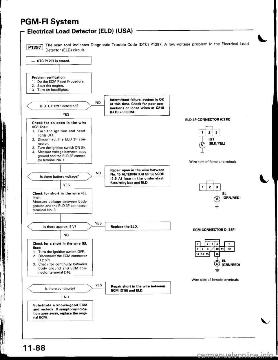
Electrical Load Detector (ELDI (USAI
The scan tool indicates Diagnostic Trouble Code (DTC) P1297: A low voltage problem in the Electrical Load
Detector (ELD) circuit.
ELD 3P CONNECTOR {C218)
Wire side of female termin€ls
Problem verification:1- Do the ECM Reset Procedure.2. Stan the engine.3. Turn on headlights.
Int€rmittont failure. swtom b OKat this time. Check tor poor con-neqtions or loose wi.es at C218IELDI and ECM-
ls DTC P1297 indicated?
Check for ao open in the wire
{lG1 linel:1. Turn the ignition and head-lights OFF.2. Disconnect the ELD 3P con-nector,3. Turn the ignition switch ON (ll).
4. Measure voltage betlveen bodyground and the ELD 3P connector te.minal No.'1.
Repair op6n in the wire baiwe€nNo. 15 ALTERNATOR SP SENSOR17.5 Al fus€ in the under-dashluse/relay box and ELD.
Chock lor short in the wire {ELline,:Measure voltage between bodyground and the ELD 3P connectorterminal No.3.
ls there approx. 5 Vl
Check for a short in the wire (EL
linel:1. Turn the ignition switch OFF.2. Disconnect the ECM connectorD (16P).
3. Check for continuity betweenbody ground and ECM con-nector terminal D16.
Sooair short in the wire betweenECM (D161 and ELD.
Substitut€ a known-9ood ECMand recheck. It symptom/indica-tion goes away, r€place the origi-nal ECM.
EL{GRN/REDI
ECM CONNECTOR D {16PI
Wire side oI Iemale tarminals
11-88
Page 293 of 1680
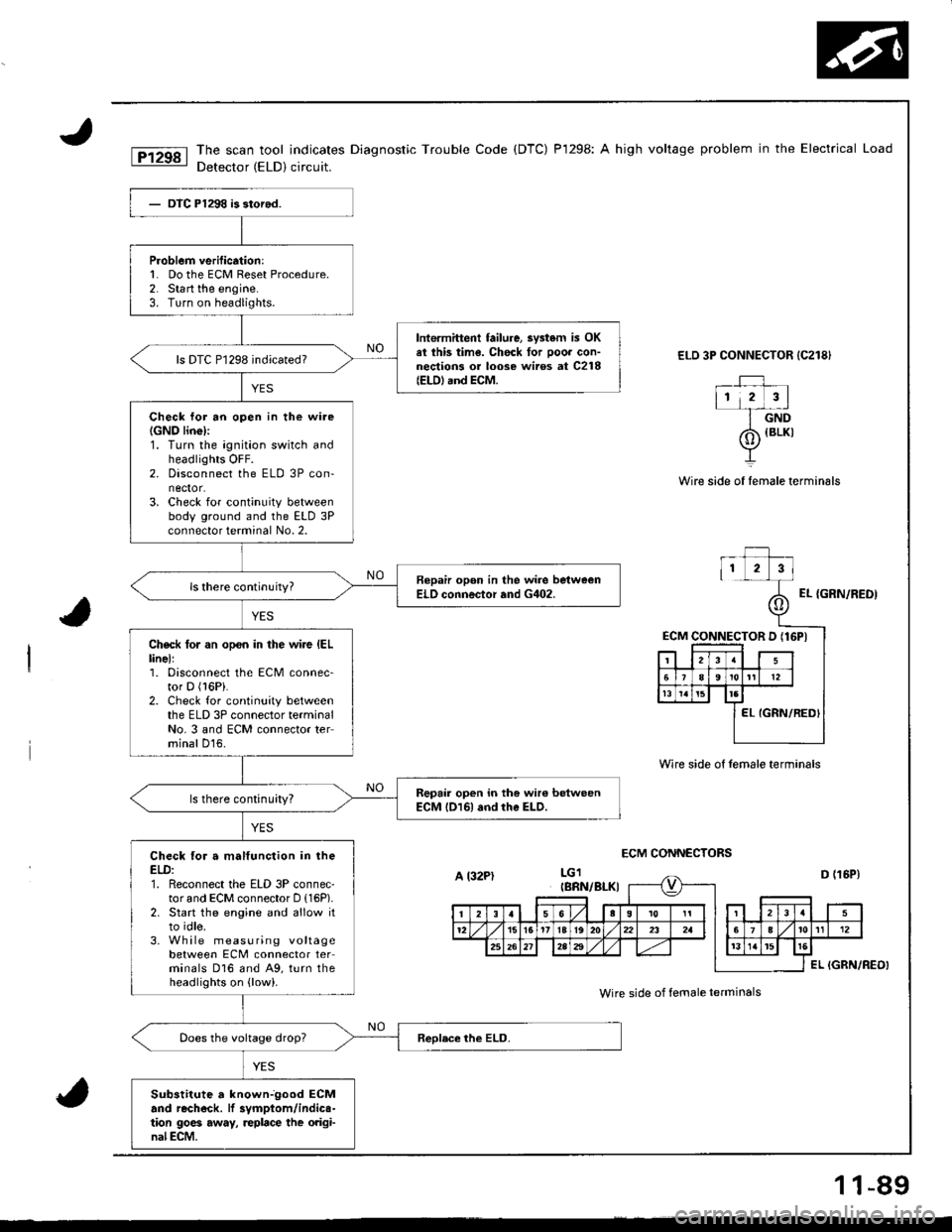
The scan tool indicates Diagnostic Trouble Code (DTC) P1298: A high voltage problem in the Electrical Load
Detector (ELD) circuit.
ELD 3P CONNECTOR {C218}
_rJ ,112 3l-f-dnD
Wire side of female terminals
ECM CONNECTORS
{BLKI
Wire side of female termin6ls
EL {GRN/REDI
ECM CONNECTOR D (16PI
P.oblem verification:l� Do the ECM Reset Procedure.2. Start the engine.3. Turn on headlights.
lntermittent failure, 3vstem is OKel ihis time. Chock for ooor con-nections or loose wiros at C218(EtD) and ECM.
ls DTC P1298 indicated?
Check lor an open in the wire(GNO linel:1. Turn the ignition switch andheadlights OFF.2. Disconnect the ELD 3P con-nector.3. Check for continuity betweenbody ground and the ELD 3Pconnector terminal No. 2.
Bepair opon in the wire bstweenELO connector and G402.
Check tor an opon in the wire IELlinell1. Disconnect the ECM connec-tor D (l6Pi.
2. Check for continuity betweenthe ELD 3P connector terminalNo. 3 and ECM connector terminal D16.
Repair open in the wir€ betweenECM l016l and rhe ELD.ls there continuity?
Check for a malfunction in theELD:1. Reconnect the ELD 3P connec-tor and ECM connector D (16P).
2. Start the engine and allow itto idle.3. Wh ile measuring voltagebetween ECM connector terminals D16 and A9, turn theheadlights on {low).
Sub3titute a knownjgood ECMand rechock. lf 3vmptom/indics-tion 9oe6 away, replace the original ECM.
A l32PtIBRN/BI-KI
Wire side of female ierminals
1 1-89
Page 346 of 1680
lT
Emission Control System
YES
{To page 11-143}
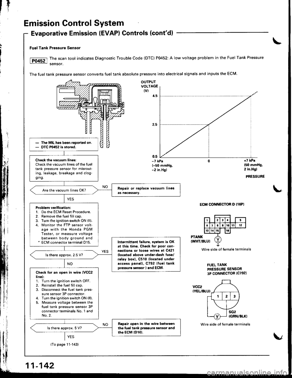
Fu€l Tank Pressure Sensor
The scan tool indicates Diagnostic Trouble Code (DTC) P0452: A low voltage problem in the Fuel Tank Pressure
sensor.
The fuel tank pressure sensor converts tuel tank absolute pressure into electrical signals and inputs the ECM.
Evaporative Emission (EVAP) Controls (cont'dl
OUTPUTVOLTAGE(vl
4.5
0.5-7 kPel-50 mmHg,-2 in.Hgl
+7 lPe
l5o mmHg,2 in.Hgl
PRESSURE
\*
Eclrl CONNECToR o {lEPl
PTANK(wltT/BLul
vcc2IYEL/BLU}
Wire side of lemale terminals
FUEL TANKPRESSURE SENSOR
3P CONNECTOR (C792)
The MIL ha3 beon roportod on.OTC F0452 i3 storad.
Chock the vscuum lines:Check the vacuum lines otthe fueltank pressure sensor for misrout-ing, leakage, breakage and clog-ging.
Are the vacuum lines OK?
Problgm verilication:1. Do the ECM Reset Procedure.2. Remove the fuel fill cap.3. Turn the ignition switch ON lll).4. Monitor the FTP sensor volt-age with the Honda PGMTester, or measure voltagebotween body ground and' ECM connector terminal D15.Int6rmittent tailure, 3ystem i3 OKat thb tirn6. Chock lor poor con-n.clions or loo3e wire3 ot C421{locltod rbovo under-d!.h fuso/r.lay boxl, C510 lloc.ted undo.rcc.rs panoll, C?92 Ituel trnko.6sura i€nior I lnd ECM.
ls there approx.2.5 V?
Check to. an opon in wi.a {VCC2line):1. Turn the ignition switch OFF.2. Reinstall the fuel fill cap.3. Disconnect the luel tank pres'su re sensor 3P connector.4. Turnthe ignition switch ON (ll).
5. Measure voltage between thetuel tank pressure sensor 3Pconnector terminals No, 1 andNo.2.
R.pai. opcn in thg wir6 bdtwoonthc fual tank pro$ure 3enlor andtho EcM lDlo).ls there approx. 5 V?
11-142
Wire side oI temale terminals
Page 417 of 1680
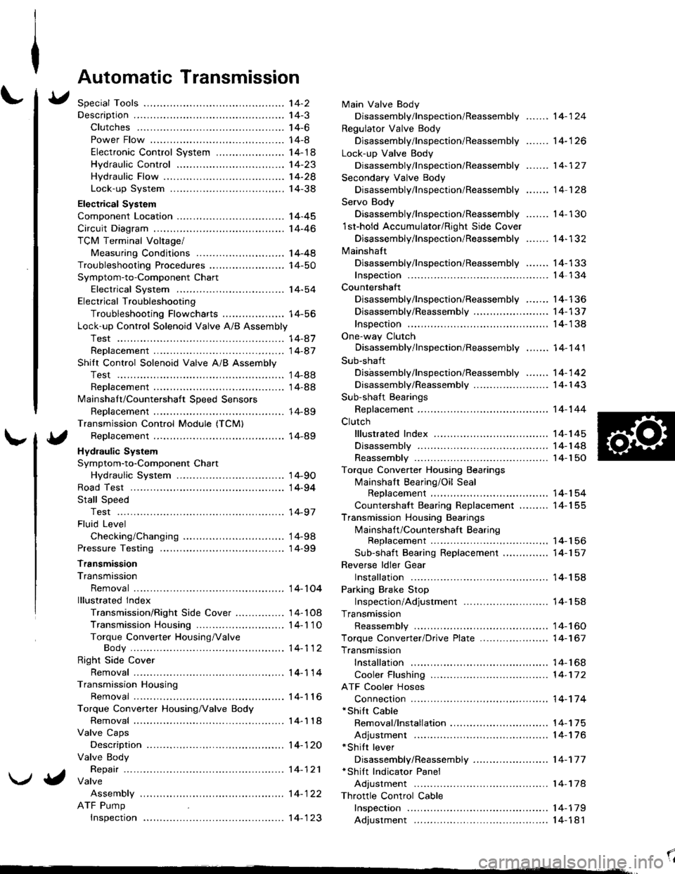
Automatic Transmission
Special Tools ................ '14-2
Descraption .................... 14-3
Clutches ............ ...... 14-6
Power Flow ..,........... 14-8
Electronic Control System ..................... 1 4-1 8
Hydraulic Control ...... 14-23
Hydraulic Flow .........- 14-28
Lock-up System ........ 14-38
Electrical System
Component Location -................................ 1 4-45
Circuit Diagram ............. 14-46
TCM Terminal Voltage/
Measuring Conditions ......,.................... 1 4-48
Troubleshooting Procedures .. . ... ........ ...... ... 14-50
Symptom-to-Component Chart
Electrical System ...... 14-54
Electrical Troubleshooting
Troubleshooting Flowcharts .......... ... ...,.. 14-56
Lock-up Control Solenoid Valve A/B Assembly
Test .................. ...... 14-A7
Replacement ............. 14-a7
Shilt Control Solenoid Valve A/B Assembly
Test .................. ...... '14-88
Replacement .,..,........ 14-88
lvlainshaf t/Countershaft Speed Sensors
Replacement ....-......,. 14-89
Transmission Control Module (TCM)
Replacement ............. 14-89
Hydraulic System
Symptom-to-Component Chart
Hydraulic System ...... 14-90
Road Test ,................... 14-94
Stall Speed
Test .................. ...... 14-97
Fluid Level
Checking/Changing .... 14-98
Pressure Testing ........... 14-99
Transmission
Transmission
Removal ............. ...... 14-10�4
lllustrated lndex
Transmission/Right Side Cover ............... 1 4-1 08
Transmission Housin9 ................,..,....... 1 4-1'1 O
Torque Converter Housing/ValveBody .................. .. 14-112
Right Side Cover
Removal ............. ...... 14-114
Transmission Housing
Removal ............. ...... 14-1 l6
Torque Converter Housing/Valve Body
Removal ............. ...... l4-1 18
Valve Caps
Description ...........-... 14-120
Valve Body
Repair ................ ...... 14-12'l
Valve
Assembly
ATF Pump
Inspeclton
Main Valve Body
Disassembly/lnspection/Reassembly
Regulator Valve Body
Disassembly/lnspection/Reassembly
Lock-up Valve Body
Disassembly/lnspection/Reassembly
Secondary Valve Body
Disassembly/lnspection/Reassembly
Servo Body
....... 14-124
....... 14-126
....... 14-127
....... 14 124
Disassembly/lnspection/Reassembly .......
1st-hold Accumulator/Right Side Cover
Disassembly/lnspection/Reassembly .......
Mainsha{t
14-130
14-132
Disassembly/lnspection/Reassembly ....... 14-133
Inspection ................. 14-134
Countershaft
Disassembly/lnspection/Reassembly,..,.., l4-136
Disassembly/Reassembly ..,...,..,.........,,.. 1 4-1 37
Inspection ......,...,..,... 14-138
One-way Clutch
Disassembly/lnspection/Reassembly ....,.. 14-141
Sub-shaft
Disassembly/lnspection/Reassembly ...,,..'14-142
Disassembly/Reassembly ....................... 1 4- l 43
Sub-shaft Bearings
Replacement ,..,,.,,..,.. 14-144
Clutch
lllustrated Index ................................... I 4-1 45
Disassembly ............. 14-144
Reassembly .............. 14-150
Torque Converter Housing Bearings
Mainshaft Bearing/Oil Seal
Replacement ......... 14-154
Countershaft Bearing Replacement ......... 1 4- 1 55
Transmission Housing Bearings
Mainshaft/Countershaft BearingReplacement ......,.. 14-'156
Sub-shaft Bearing Replacement .,............ 1 4-1 57
Reverse ldler Gear
Installation .........-..... 14-158
Parking Brake Stop
Inspection/Adjustment .......................... 1 4-1 58
Transmission
Reassembly .............. 14-160
Torque Converler/Drive Plate ..............,.,,.,, 1 4-1 67
Transmission
Installation ............... 14-168
Cooler Flushing ......... 14-172
ATF Cooler Hoses
Connection ,..,,,....,,.,, '14-'174
*shift cable
Removal/lnstallation . . .. .... ... .... ... .... .. . ... .. 14-'l75
Adjustment ,..,...,,,,.,, 14-'116*Shilt lever
Disassembly/Reassembly ....................... 1 4-'17 7'Shift Indicator Panel
Adjustment .............. 14-178
\l
)g
Page 466 of 1680
![ACURA INTEGRA 1998 Service User Guide Troubleshooting Procedures
Checking the Diagnostic Trouble Code (DTC)
with an OBD ll Scan Tool or th€ Honda PGM Tester
When the TCM senses an abnormality in the input or output systems, the lD,] ind ACURA INTEGRA 1998 Service User Guide Troubleshooting Procedures
Checking the Diagnostic Trouble Code (DTC)
with an OBD ll Scan Tool or th€ Honda PGM Tester
When the TCM senses an abnormality in the input or output systems, the lD,] ind](/img/32/56983/w960_56983-465.png)
Troubleshooting Procedures
Checking the Diagnostic Trouble Code (DTC)
with an OBD ll Scan Tool or th€ Honda PGM Tester
When the TCM senses an abnormality in the input or output systems, the lD,] indicator light in the gauge assembly will
blink. When the 16p Data Link Connector (DLC) (located under the dash on the passenger side) is connected to the OBD ll
Scan Tool or Honda PGM Taster as shown, the scan tool or tester will indicate the Diagnostic Trouble Code (DTC) when
the ignition switch is turned ON {ll}.
When the !r indicator light has been reported on, connect the OBD ll Scan Tool confirming to SAE J1978 or Honda PGM
Tester to the DLC (16P) behind the ashtray. Turn the ignition switch ON (ll) and observe the DTC on the screen ofthe OBD
ll Scan Tool or Honda PGM Tester. After determining the DTC, refer to the electrical system Symptom-to-Component
Chart on pages 14-54 and 14-55.
NOTE: SeetheOBDll ScanTool orHonda PGM Tester user's manual for specific instructions.
OBD-IlSCAN TOOL orHONDA PGM TESTER
Some PGM-Fl problems will also make the lol indicator light come on. After repairing the PGM-Fl system. disconnect the
BACK Up fuse (7.5 A) in the under-hood fuse/relay box for more than 10 seconds to reset the TCM memory, then recheck.
NOTE: Disconnecting the BACK UP fuse also cancels the radio anti-theft code, preset stations and the clock setting. Get
the customer's code number, and make note of the radio presets before removing the fuse so you can reset them
uJ trr
ulu
ai
14-50L
DATA LINK CONNECTOR (16P)
I
il
lt
rJq
Page 467 of 1680
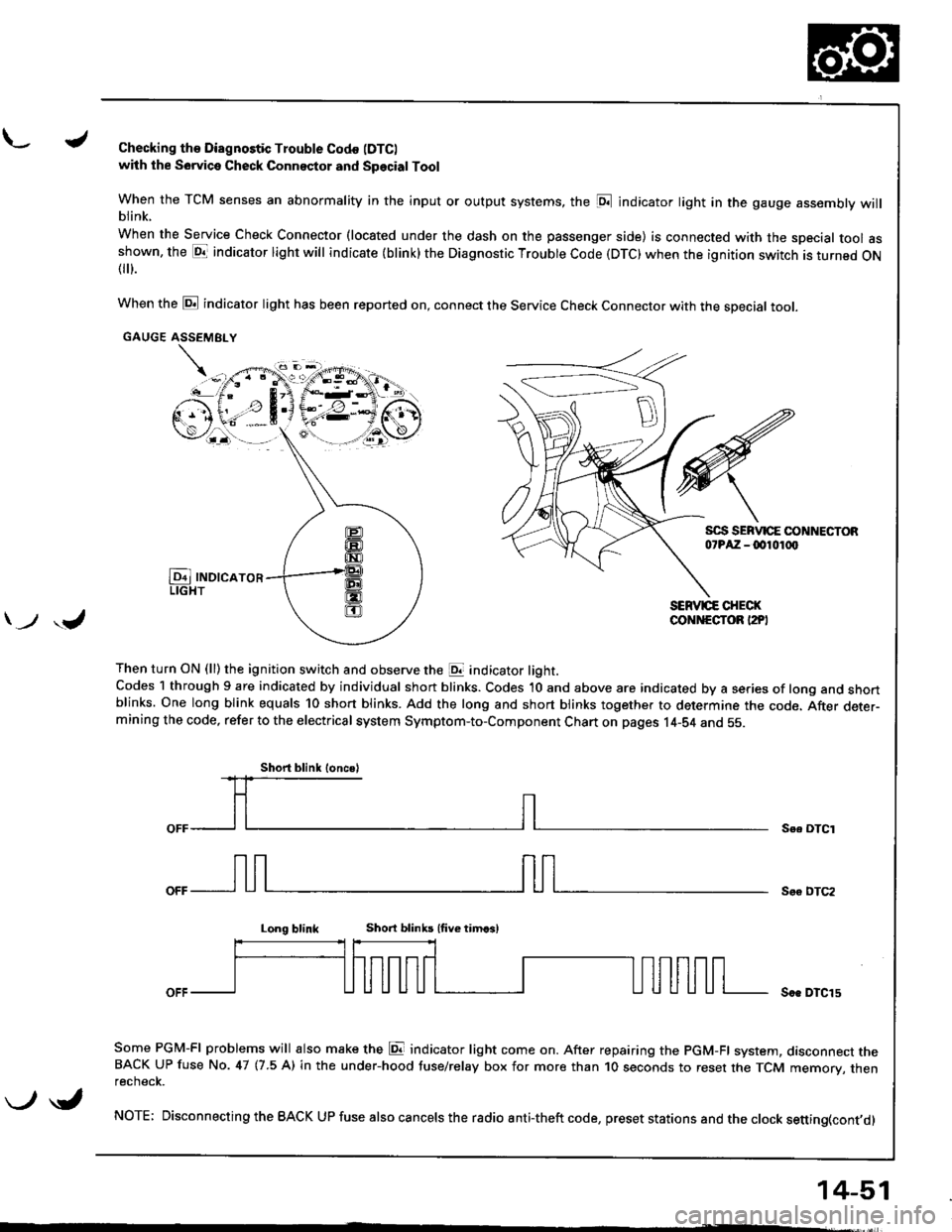
L./Checking th€ Diagnostic Trouble Codo (DTC)
with the Sowica Check Connector and Special Tool
When the TCM senses an abnormality in the input or output systems, the [D;l indicator light in the gauge assembly willblink.
When the Service Check Connector (located under the dash on the passenger side) is connected with the special tool asshown, the E1T indicator light will indicate (blink) the Diagnostic Troubte Code (DTC) when the ignition switch is turned ON{
}.
When the @ indicator light has been reported on, connect the Service Check Connector with the special toot.
GAUGE ASSEMEI.Y
Then turn ON (ll) the ignition switch and observe the E indicator light.Codes 1 through 9 are indicated by individual short blinks. Codes 1O and above are indicated by a series of long and shortblinks. One long blink equals 10 short blinks. Add the long and short blinks together to determine the code. After deter-mining the code, refer to the electrical system Symptom-to-Component Chart on pages 14-S4 and 55.
\-F;ii^r
) ,J
Se. OTCI
Soo DTC2
Long blinkShort blinb lfive timcsl
Soe DTCl5
Some PGM-FI problems will also make the E indicator light come on. After repairing the PGM-FI system, dasconnect theBACK UP fuse No. 47 (7.5 A) in the under-hood tuse/relay box for more than 1O seconds to reset the TCM memory, thenrecnecK.
NOTE; Disconnecting the BACK UP fuse also cancels the radio anti-theft code, preset stations and the clock setting(cont,d)
Short blink loncsl
\-/ \i,
14-51