sub ACURA INTEGRA 1998 Service Repair Manual
[x] Cancel search | Manufacturer: ACURA, Model Year: 1998, Model line: INTEGRA, Model: ACURA INTEGRA 1998Pages: 1680, PDF Size: 53.14 MB
Page 87 of 1680
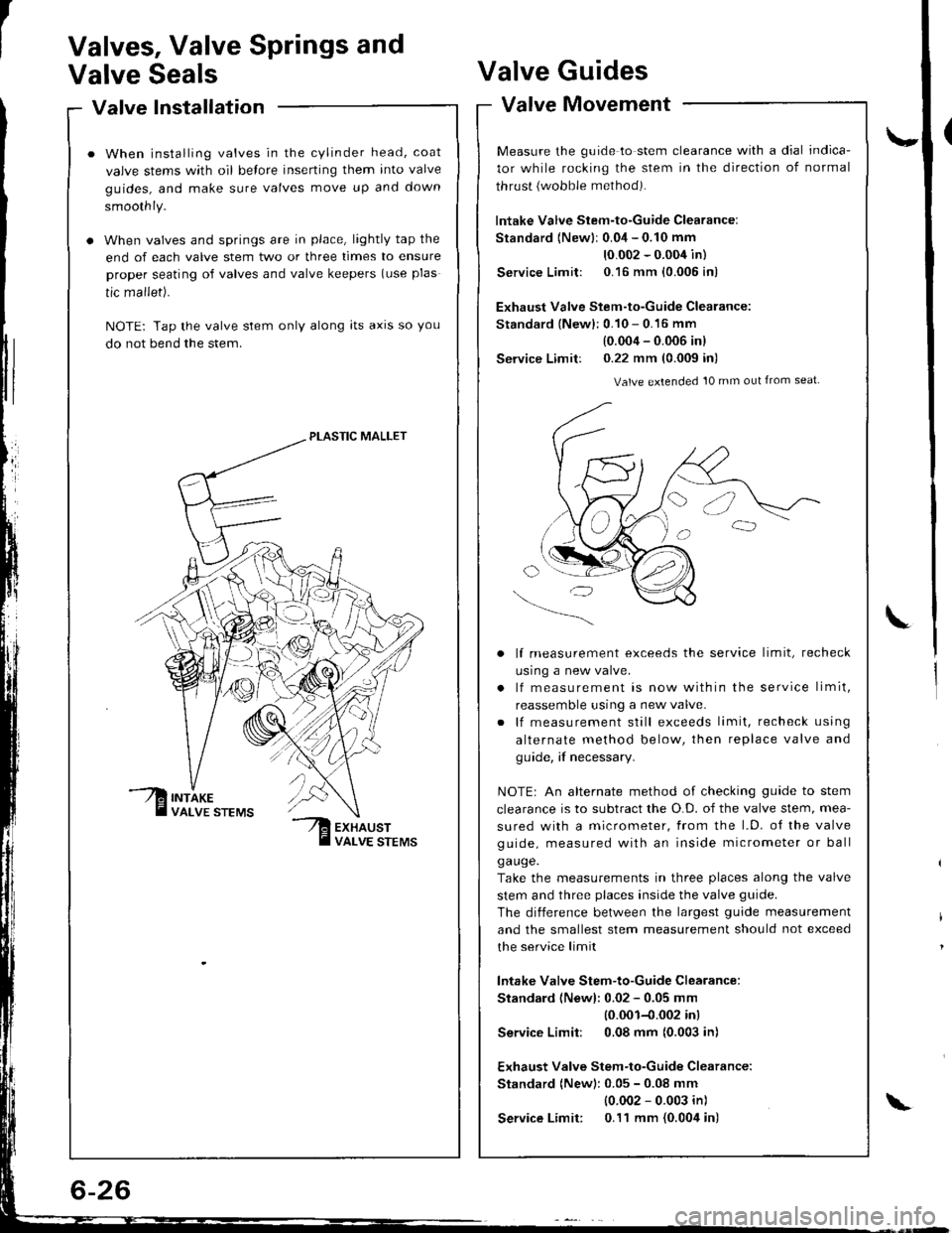
Valve Installation'alve Inslallauon -
When installing valves in the cylinder head, coat
valve stems with oil belore inserting them into valve
guides, and make sure valves move up and down
smoothly.
When valves and springs are in place, lightly tap the
end of each valve stem two or three times to ensure
proper seating of valves and valve keepers (use plas
tic mallet).
NOTE: Tap the valve stem only along lts axrs so you
do not bend the stem.
PLASTIC MALLET
Valves, Valve Springs and
Valve SealsValve
Valve
Guides
Movement
\-
L
valve tvtovemenr -
Measure the guide to stem clearance with a dial indica-
tor while rocking the stem in the direction of normal
thrust {wobble method).
lntake Valve Stem-to-Guide Clearance:
Standard {Newlr 0.04 - 0.10 mm
10.002 - 0.004 in)
Service Limit: 0.16 mm {0.005 in)
Exhaust Valve Stem-to-Guide Clearance:
Standard {New}: 0.10 - 0.16 mm
(0.004 - 0.006 inl
Service Limit: 0.22 mm (0.009 in)
Valve extended 10 mm out from seat
lf measurement exceeds the service limit, recheck
usrng a new valve.
lf measurement is now within the service limit,
reassemble using a new valve.
lf measurement still exceeds limit, recheck using
alternate method below, then replace valve and
guide, if necessary.
NOTEr An alternate method of checking guide to stem
clearance is to subtract the O.D. of the valve stem, mea-
sured with a micrometer, from the l.D. o{ the valve
guide, measured with an inside micrometer or ball
ga uge.
Take the measurements in three places along the valve
stem and three places inside the valve guide.
The diiference between the largest guide measurement
and the smallest stem measurement should not exceed
the service limit
lntake Valve Stem-to-Guide Clearance:
Standard (Newl: 0.02 - 0.05 mm
10.001-{.002 inl
Service Limit: 0,08 mm (0.003 in)
Exhaust Valve Stem-to-Guide Clearance:
Standard (New): 0.05 - 0.08 mm
{0.002 - 0.003 in)
Service Limit: 0.11 mm {0.004 in)\
Page 176 of 1680
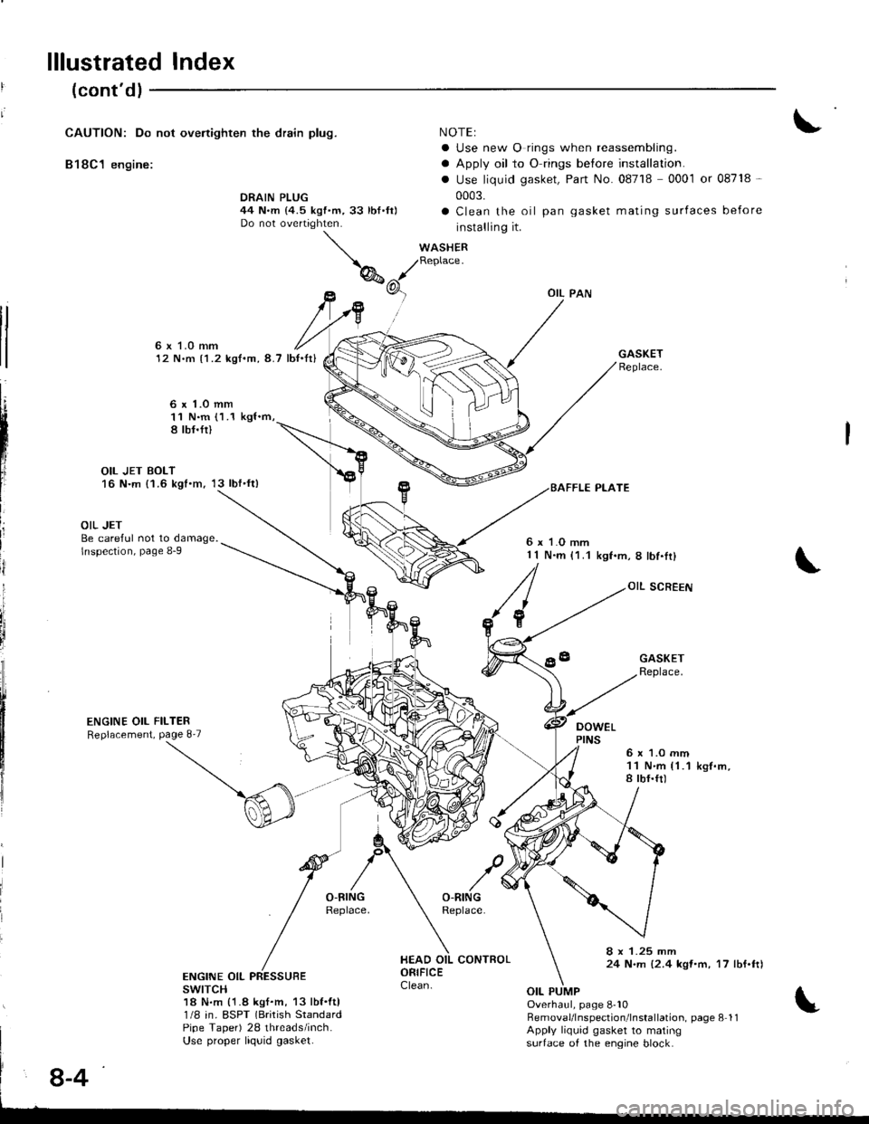
lllustrated Index
(cont'dl
CAUTION: Do not ovenighten the drain plug.
B18C1 engine:
NOTEI
a Use new O rings when reassembling.
a Apply oil to O rings before installation.
. Use liquid gasket, Part No. 08718 0001 or 08718 -
0003.
a Clean the oil pan gasket mating surfaces before
installing it.
WASHERReplace.
DRAIN PLUG44 N.m {4.5 kgf.m,33 lbf.ft)Do not overtighten.
tl
tl
6x LO mm12 N.m {1.2 kgf.m, 8.7 lb{.It}
6 x 1.o mm11 N.m (1.1 kgl.m,8 tbf.fi)
OIL JET BOLT16 N.m {1.6 kgt.m, 13 lbf'ft)
L
III
ij
i
OIL JETBe careful not to damage.lnspection, page 8-9
ENGINE OIL FILTERReplacement, Page 8'7
6 x 1.O mm1 1 N.m (1.1kgf.m,8lbf.Ir)
OIL SCREEN
DOWEL
GASKETReplace.
6x 1.O mm11 N.m {1.1a tbf.ft)k9f.m,
8 x 1.25 mm24 N.m {2.4 kqt'm, 17 lbf.ftlENGINE OIL PRESSUBEswrTcH18 N.m {1.8 kgf.m, 13 lbf.ftl1/8 in. ESPT (Brirish StandardPipe Taper) 28 threads/inch.Use proper liquid gasket.
Overhaul, page 8-10RemovaUlnspection'lnstallation. page 8 11Apply liquid gasket to matingsurtace of the engine block.
8-4
Page 216 of 1680
![ACURA INTEGRA 1998 Service Repair Manual System Description
Vacuum Connections (contdl
Bl8Cl engine:
rl
llj
lli;r
Fil
ryl
xr
flti
li
tl
I
lr; I
,l{9^h;L-r
-1] PRIMARY HEATED OXYGEN SENSOR IPRIMARY HO2SItsENsoR 1l
O SECONDARY HEATED OXYGE ACURA INTEGRA 1998 Service Repair Manual System Description
Vacuum Connections (contdl
Bl8Cl engine:
rl
llj
lli;r
Fil
ryl
xr
flti
li
tl
I
lr; I
,l{9^h;L-r
-1] PRIMARY HEATED OXYGEN SENSOR IPRIMARY HO2SItsENsoR 1l
O SECONDARY HEATED OXYGE](/img/32/56983/w960_56983-215.png)
System Description
Vacuum Connections (cont'dl
Bl8Cl engine:
rl
llj
lli;r
Fil
ryl
xr
flti
li
tl
I
lr; I
,l'{9^h;'L-r
'-1] PRIMARY HEATED OXYGEN SENSOR IPRIMARY HO2SItsENsoR 1l
O SECONDARY HEATED OXYGEN SENSOR (SECONDARY
HO2SI ISENSOR 2)
.3) MANIFOLD ABSOLUTE PRESSUBE {MAPI SENSORii ENGINE COOLANT TEMPERATURE (ECT} SENSORii INTAKE AIR TEMPERATURE IIAT) SENSORi6-- CRANKSHAFT SPEEO FLUCTUATION ICKF} SENSOR
a7) KNocK sENsoR lKslO IDLE AIR CONTROL IIAC) VALVE
i' FUEL INJECTOR
@ FUEL FILTER
O FUEL PRESSURE REGULATOR
[4 FUEL PUMP {FP}@ FUEL TANKI.13 FUEL TANK EVAPORATIVE EMISSION (EVAP) VALVE
.19 FUEL PULSATION DAMPER{!9 AIR CLEANER
O RESONATOR
I t-az
I: Vacuum hose No.
iio INTAKE AIR BYPASS IIAE) CONTROL DIAPHRAGM VALVE(!9) INTAKE AIR BYPASS {IABI CONTROL SOLENOID VALVE
6I INTAKE AIR BYPASS (IAB) VACUUM TANK
CI INTAKE AIR BYPASS {IABI CHECK VALVE
€9 THREE WAY CATALYTIC CONVEFTER (TWC)
2jI POSITIVE CRANKCASE VENTILATION (PCV} VALVE
€! EVAPORATIVE EMISSION (EVAPI CONTROL CANISTER
?9 EVAPORATIVE EMISSION {€VAPI PURGE CONTNOLSOLENOID VALVE0d EVAPORATIVE EMISSION (EVAP}TWO WAY VALVE
iii) EVAPORANVE EMISSION {EVAP) BYPASS SOLENOID VALVE,3 EVAPORAIVE EMTSSTON {EVAP} CONTROL CANISTER VENTSHUT VALVE?9 FUEL TANK PRESSUR€ SENSORi3O] EVAPORATIVE EMISSION IEVAP} THREE WAY VALVE
Page 254 of 1680

I
I
It:
PGM-FI System
Engine Control Module {ECMI
,i
I
{
ili
NOTE: lf this svmotom is intermittent, check for a loose fuse No. 25 METER (7.5A) in the under_
dash fuse/relay box, a ooor connection at ECM terminal A18, or an intermittent open in the
GRN/ORN wire between the ECM (A18) and the gauge assembly.
Wire side of female terminals
I
The Mellunction Indicator Lamp(MlLl never com€3 on leven foltwo secondsl alter ignition islurn6d ON lll).
Turn the ignition switch ON (lli.
- Repair short or open in th€wire betwe€n No. 25 METER{7.5 A}fuse and gauge assem-bty.- ReDlaco No.25 METER 17.5 A)fuse.
ls the low oil pressure light on?
Try to start the engine,
Check for an open in ih6 wires
IPG lines):1. Turnthe ignition switch ON (ll).
2. Measure voltage betweenbody ground and ECM connec-tor terminals A10 and A23 indi-vidually.
Chock for an open in the wire orbulb:1. Turn the ignition sw;tch OFF.2. Connectthe ECM connector terminal 418 to body ground with
3. Turn the ignition switch ON (ll).
Repair open in the wire(slbetween ECM and G101 (located
at thermostat housingl that hadmore than 1.0 V.
ls there less than 1.0 V?
Substitute . known-good ECMand .echeck, lf symptom/indica-tion goes away, replace the origi-nalECM.
- R€pair open in the wiresb€tweon ECM {A18land gaug€
ess€mbly.- Replace the MIL bulb.
ls the MIL on?
Substitute a known-9ood ECMand rech6ck. It symptom/indica-tion goes away, repbce the origi-nal ECM.
ECM CONNECTOR A {32P)
15 16 17 18 19
r 2 3 al 15 Ga910 11
12 ,, t5 16 1tt920/22 23 2a
25 26 211184tt-MILJUMPER(GRN/ORN) I WIRE
Page 256 of 1680

PGM.FISystem
Gontrol Module (ECMI (cont'dlEngine
\
L
(From page 11-51)
Choc* tol s short in tho wir6 lMlLlino):1. Turn the ignition switch OFF.2. Disconn€ct the ECM conn6c-tor A (32P).
3. Turn the ignition switch ON (ll).
Repair 3hon to body ground in
rhe wire bstw.on tho ECM (A181
and MlL.
Substituto s known-good ECMend rechock. H 3ymptom/indica-tion goes awry, replacc tho origi-nelECM,
{From page 11-51)
Inspect Fl E/M (15 A) fuse in theunder-hood Iuse/relay box.
- Ropsir short in tha wircbotw.on Fl E/M {'15 Al tu3c'rnd PGM-FI m.in t.lry.- Rool.c. Fl E/M l15A)tu!€.
Inspect No. 13 FUEL PUMP (SRS
UNIT) ('l5A) fuse in the undeFdash fuse/relay box.
- Reo.ir sholt in th. wirobotw..n No. 13 FUEL PUMP
{SRs UNIT) (15 Al fur..ndFGM-FI m.in rclay.- Repl.co No. 13 FUEL PUMP(SRS UNIT) {15 Alturr.
Ch6ck for . shon in a son3or1. Turn the ignition switch ON (ll).
2. Disconnect the 3P connectorfrom oach sensor one at time:. MAP sensor. TP sensor. Fueltank pressure sensor
Rapl.cc tha 3onaor thrt cauaadihe light to 9o out.Does the MIL go OFF?
1-52
(To page 11-53)
Page 257 of 1680
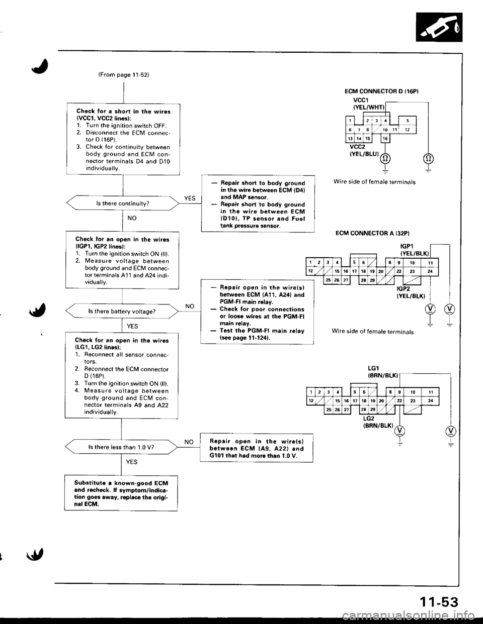
{From page 11 52)
Chock lor a shon in lhe wi.asiVCC1. VCC2lin$l:1. Turn the ignition switch OFF-2. Disconnect the ECM connec,tor D (16P).
3. Check lor continuity betweenbody ground and ECM con-nector terminals D4 and D10individually.
- Repair short to body groundin tho wire between ECM {D4land MAP 3enso..- Rep.ir short to body groundin the wire between ECMlD10l, TP sensor and Fueltank pa6ssure sanso..
Chock lor an op€n in the wire3{lGP1.lGP2lines):1. Turn the ignition switch ON (ll).2, Measure voltage betweenbody ground and ECM connec-torterminals A'11 and A24 indi-vadually.- R6pe;r open in the wire{slbetween ECM 1A11, A24l andPGM-FI main .elay.- Check for poor connectionsor loose wi.es at the PGM-FImain relay.- Test tho PGM-FI main ral.v(see page 11-124).Check for an open in the wires(LG1, LG2line3l:1. Reconnect all sensor connec-tors.2. Reconnect the ECM connectorD (16P).
3. Turn the ignition switch ON (ll).4- M easu re voltage betweenbody ground and ECM connector terminals A9 and A22individually.
Repai. open in the wir€ls)bctween ECM {A9, A22l .ndG101 ihet had more then 1.0 V.
ls there lessthan 1.0 V?
Substitute , known-good ECMand rechock. f symptom/indica-tion goes away, roplac6 the odgi-n3l ECM.
Wire side of female terminals
ECM CONNECTOR A I32P)
a,
Wire side of female terminals
LGl
1 1-53
Page 259 of 1680
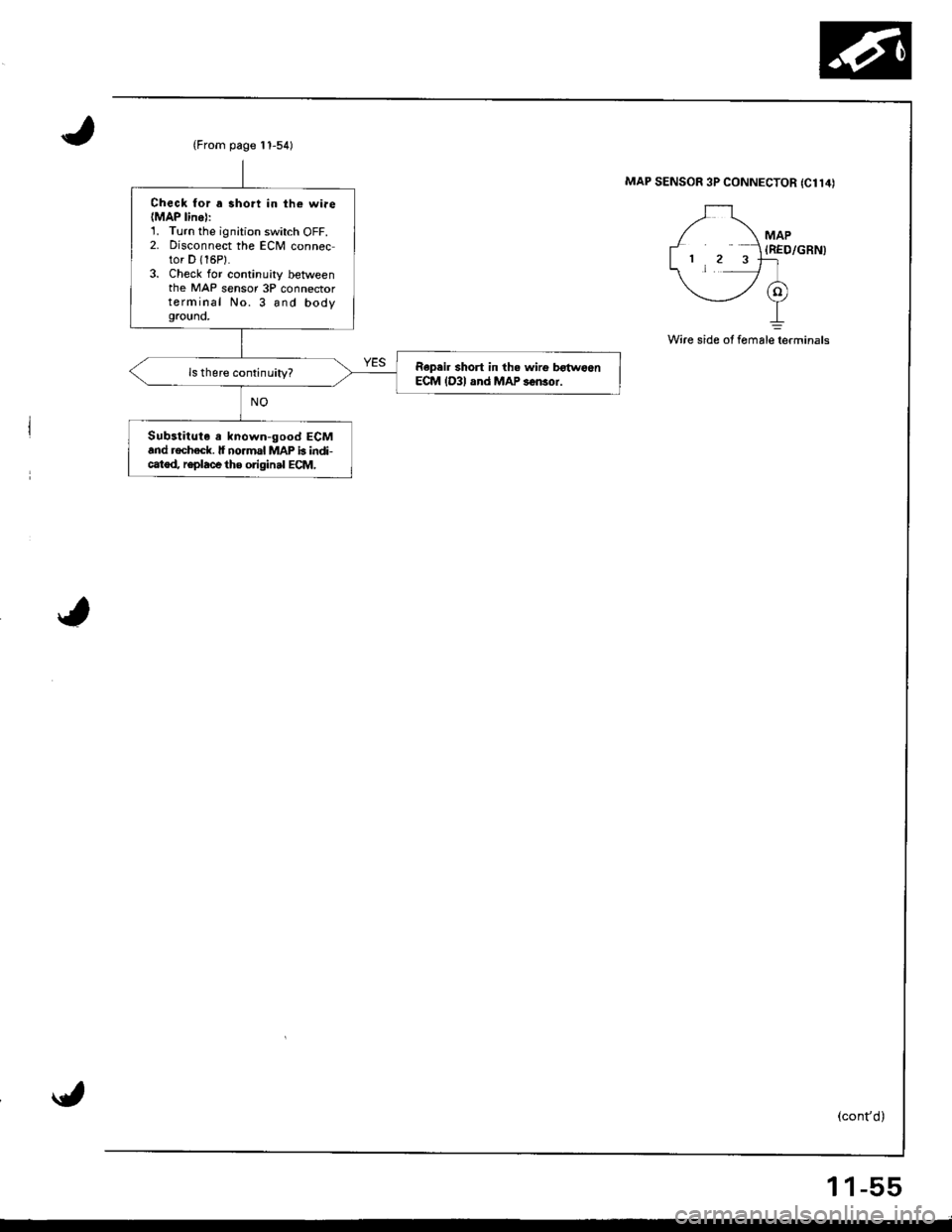
(From page t 1-54)
Check for a 3hort in th€ wiae(MAP linel:1. Turn the ignition switch OFF.2. Disconnect the ECM connector D {16P}.3. Check for continuity betweenthe MAP sensor 3P connectorterminal No. 3 and bodygrouno,
Repeir short in th. wirg b€{woenECM lD3l and MAP s6n3or.
Substitute a known-good ECMand rochack. lf no.mal MAP b indi-catod, r€place the original ECM,
MAP SENSOR 3P CONNECTOR {C114)
MAP(RED/GRN)
Wire side of fomalelerminals
1 1-55
Page 260 of 1680
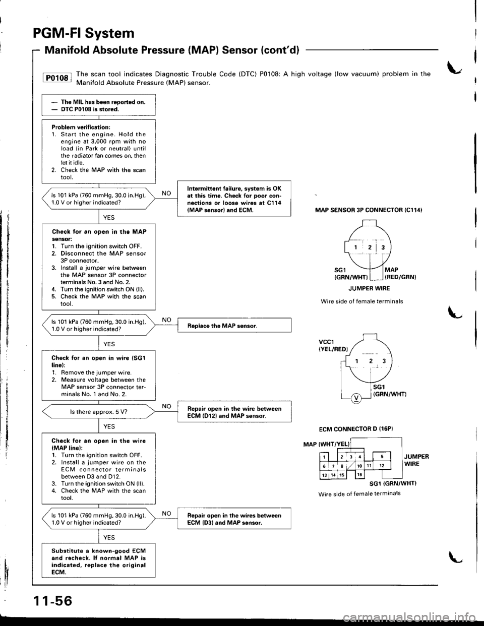
PGM-FI System
Manifold Absolute Pressure (MAPI Sensor (cont'dl
tF'r'sl li:"J:ilfi::il***:ilHi""k:"
code (Drc) P0108' A hish vo*ase (row vacuum) probrem in the
Thc MIL has b6en reoortod on.OTC P0108 is stored.
Problem veritication:1. Start the engine. Hold theengine at 3,000 rpm with noload (in Park or neutral) untilthe radiator fan comes on, thenlet it idle.2. Check the MAP wlth the scantool,
Intermittent f.ilure, svstem is OKal this time. Check lor Door con-nections or loose wires at C114{MAP sensor} and ECM.
ls 101 kPa (760 mmHg,30.0 in.l-lg),1.0 V or higher indicated?
Chock tor an opcn in th. MAPs€nsoa:1. Turn the ignition switch OFF.2. Disconnect the MAP sensor3P connector.3. Install 6 jumper wire betweenthe MAP sensor 3P connectorterminals No.3 and No.2.4. Turn the ignition switch ON (ll).
5. Ch€ck the MAP with the scantool.
ls 101 kPa (760 mmHg,30.0 in.Hg),1.0 V or higher indicated?
Check tor an open in wire (SG1
linel:1. Remove the jumper wire.2, Measure voltage between theMAP sensor 3P connector teFminals No. I and No.2.
Repair open in the wire betweenECM l012l and MAP s€nsor.ls there approx.5 V?
Check for an open in the wire{MAP line):1. Turn the ignition switch OFF.2. Install a jumper wire on theECM co n nector terminalsbetween D3 and Dl2.3. Turn the ignition switch ON lll).4. Check the MAP with the scantool,
ls 101 kPa (760 mmHg,30.0 in.Hg),1.0 V or higher indicated?Repair open in the wires betweenECM {D3, and MAP s6Gor.
Substitut€ a known-good ECMand recheck. It normal MAP isindicaied, rgplace the originalECM.
MAP SENSOR 3P CONNECTOR {C114}
Wire side of female terminals
L
vccr{YEL/RED)
MAP IWHT
JUMPERWIRE
SG1 (GRN/WHT}
Wire side of female terminals
1 1-56
{GRN/WHT)I ] {RED/GRN)
ECM CONNECTOR D {16P}
L
Page 262 of 1680
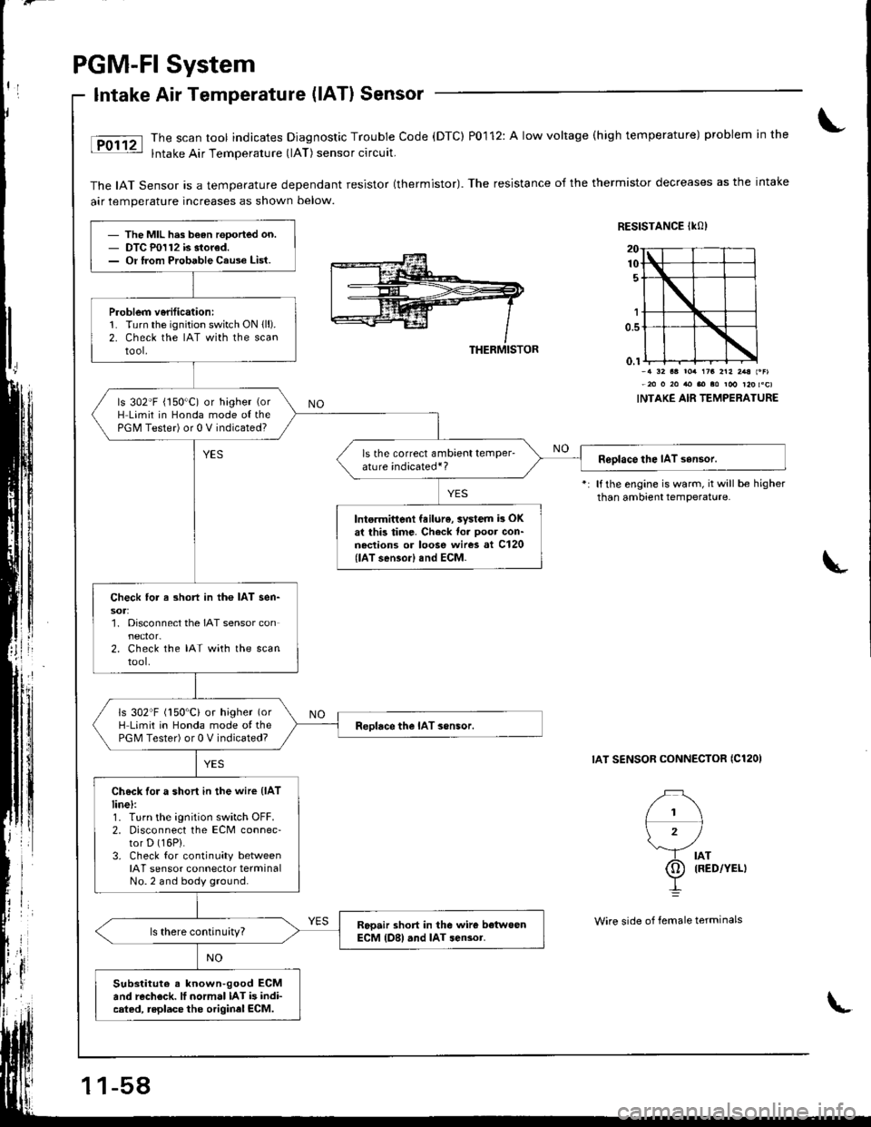
PGM-FI System
Intake Air Temperatute (lATl Sensor
The scan tool indicates Diagnostic Trouble Code (DTC) P0112: A low voltage (high temperature) problem in the
lntake Air Temperature (lAT) sensor circuit.
The IAT Sensor is a temperature dependant resistor (thermistor). The resistance of the thermistor decreases as the intake
air temperature increases as shown below.
RESISTANCE IKO)
THERMISTOR
l1\
\'/
rb lllo,'.u
I
1r3 2r2 2.a l.Flm roo r20 toc)
INTAKE AIR TEMPERATURE
lf the engine is warm, it will be higherthan ambient temperature.
IAT SENSOR CONNECTOR ICl2OI
- The MIL h.s b€an rooorted on.- DTC P0112 is stored.- Or lrom Probable Cau3e List.
P.oblem v6rificationi1. Turn the ignition switch ON lll).2. Check the IAT wirh the scantool.
ls 302'F (150"C) or higher (or
H Limit in Honda mode o{ thePGM Tester) or 0 V indicated?
ls the correct ambient temPerature indicated*?Roolace the IAT sensor.
Into.mittent feilur6, aystem h OKat this timc. Check to. Doot con-nections or loose wires at Cl20{lAT sensor) snd ECM.
Check tor a 3hort in the IAT sen-
1. Disconnect the IAT sensor con
2. Check the IAT with the scantool.
ls 302"F (150'C) or higher (or
H Limit in Honda mode of thePGM Tester) or 0 V indicated?Reolace the IAT sonsor.
Check for a short in the wire (lAT
line):1. Turn the ignition switch OFF.2. Disconnect the ECM connec-tor D (16P).
3. Check for continuity betweenIAT sensor connector terminalNo.2 and body ground.
Rooair short in the wirc botwoenECM {D8) .nd IAT sen3or.ls there continuity?
Substitut€ s known-good ECMand rccheck. lI normal IAT is indi-cated, replace the originel ECM.
1 1-58
Wire side of lemale terminals
L
Page 263 of 1680
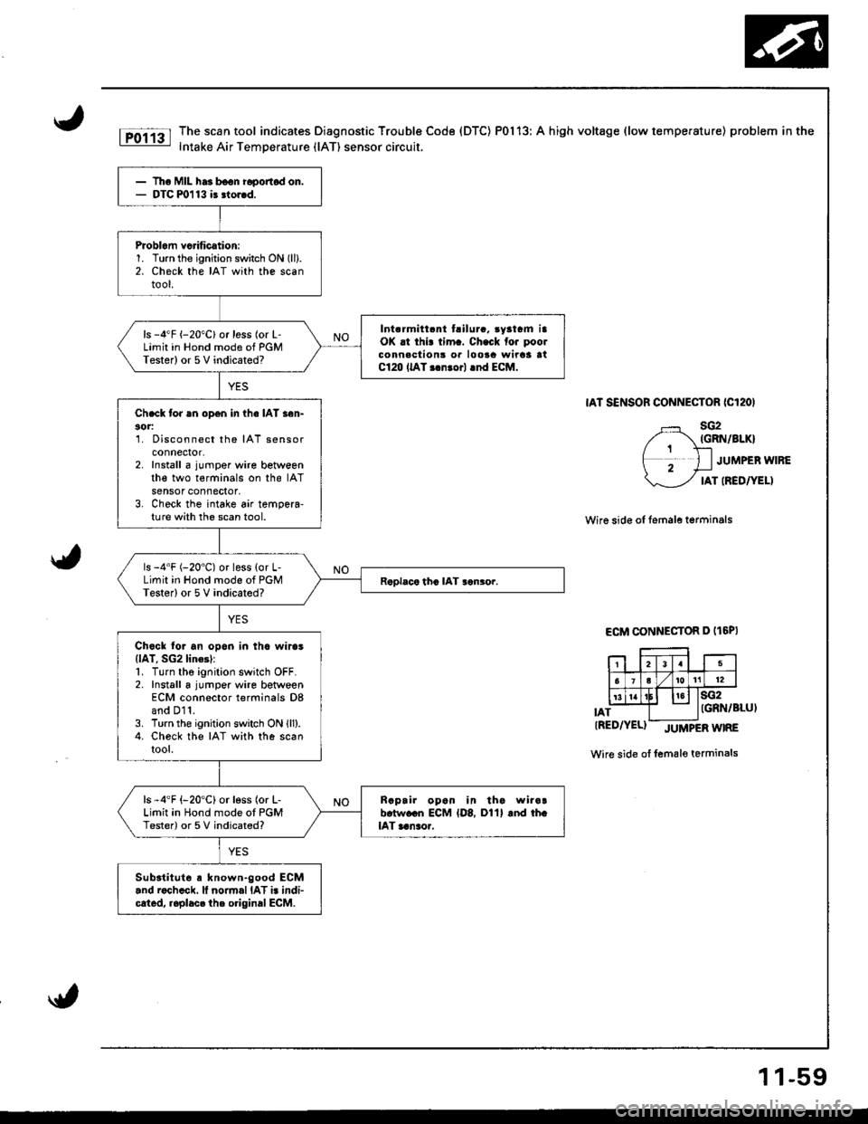
The scan tool indicates Diagnostic Trouble Code (DTC) P0113: A high voltage (low temperature) problem in the
Intake Air Temperature (lAT) sensor circuit.
IAT SENSOR CONNECTOR ICl2OI
sG2IGRN/BIKI
JUMPEB WIRE
IAT IREDTYELI
Wire side of temale terminals
ECM CONNECTOR D (t6PI
IAT
sG2IGRN/BLUI
tRED/YEL)-JUtvtPERWTRE
Wire side of female terminals
Tho MIL ha3 b€on i6ponod on.DTC m113 i3 3lor.d.
Problom vcrification:1. Turn the ignition switch ON (ll).
2. Check the IAT with the scantool.
Int.rmitt.nt t.ilura. .yatrm iaOK .t thi! tim.. Ch.ck fo. poolconnaclion3 or loota wirca atC120 llAT r.nrorl .nd ECM.
ls -4"F {-20"C}or less (or L-Limit in Hond mode of PGMTester) or 5V indicated?
Ch.ck tor an open in ihe IAT s6n-30r:1. Disconnect the IAT sensorconnectot,2. Install a jumper wire betweenthe two terminals on the IATsensor connector,3. Check the intake air tempera-ture with the scan tool.
ls -4'F (-20"C) or less {or L-Limit in Hond mode of PGMTester) or 5 V indicated?
Chock to. an opon in thc wiros(lAT, SG2 lin6l:1. Turn the ignition switch OFF.2. Install a jumper wire betweenECM connector terminals D8and D11.3. Turn the ignition switch ON lll).4. Check the IAT with the scantool.
ls -4'F {-20'C} or less (or L-Limit in Hond mode ot PGMTester) or 5 V indicated?
Raprir opan in tha wira!b.tw.cn ECM {D8, D11} and th.lAT aanao.,
Subatitut6 a known.good ECM.nd roch.ck. ll normal IAT i. indi-cated, roplacc the o.iginal ECM.
1 1-59