boot ACURA NSX 1991 Service Owner's Manual
[x] Cancel search | Manufacturer: ACURA, Model Year: 1991, Model line: NSX, Model: ACURA NSX 1991Pages: 1640, PDF Size: 60.48 MB
Page 484 of 1640
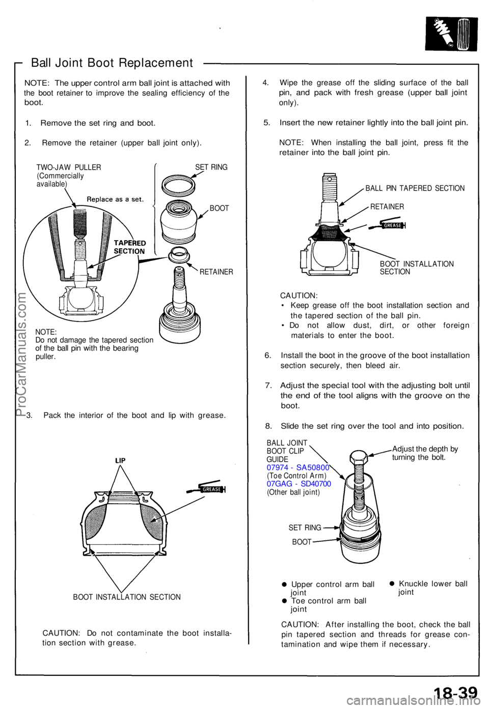
Ball Join t Boo t Replacemen t
NOTE: Th e uppe r contro l ar m bal l join t i s attache d wit h
the boo t retaine r t o improv e th e sealin g efficienc y o f th e
boot .
1. Remov e th e se t rin g an d boot .
2. Remov e th e retaine r (uppe r bal l join t only) .
TWO-JA W PULLE R(Commerciall yavailable)
SET RIN G
BOO T
RETAINE R
NOTE:Do no t damag e th e tapere d sectio nof th e bal l pi n wit h th e bearin gpuller.
3. Pack the interio r o f th e boo t an d li p wit h grease .
BOOT INSTALLATIO N SECTIO N
CAUTION : D o no t contaminat e th e boo t installa -
tio n sectio n wit h grease . 4
. Wip e th e greas e of f th e slidin g surfac e of the bal l
pin, an d pac k wit h fres h greas e (uppe r bal l join t
only) .
5. Inser t th e ne w retaine r lightl y int o th e bal l join t pin .
NOTE : Whe n installin g th e bal l joint , pres s fi t th e
retaine r int o th e bal l join t pin .
BAL L PI N TAPERE D SECTIO N
RETAINE R
BOOT INSTALLATIO NSECTION
CAUTION :
• Kee p greas e of f th e boo t installatio n sectio n an d
th e tapere d sectio n o f th e bal l pin .
• D o no t allo w dust , dirt , o r othe r foreig n
material s t o ente r th e boot .
6. Instal l th e boo t i n th e groov e o f th e boo t installatio n
section securely , the n blee d air .
7. Adjus t th e specia l too l wit h th e adjustin g bol t unti l
the en d o f th e too l align s wit h th e groov e o n th e
boot .
8. Slid e th e se t rin g ove r th e too l an d int o position .
BALL JOIN TBOOT CLI PGUID E07974 - SA5080 0(Toe Contro l Arm )07GA G - SD4070 0(Other bal l joint )
SET RIN G
BOO T
Uppe r contro l ar m bal l
join t
To e contro l ar m bal l
joint
Adjus t th e dept h b y
turnin g th e bolt .
Knuckl e lowe r bal l
join t
CAUTION : Afte r installin g th e boot , chec k th e bal l
pi n tapere d sectio n an d thread s fo r greas e con -
taminatio n an d wip e the m if necessary .
ProCarManuals.com
Page 497 of 1640
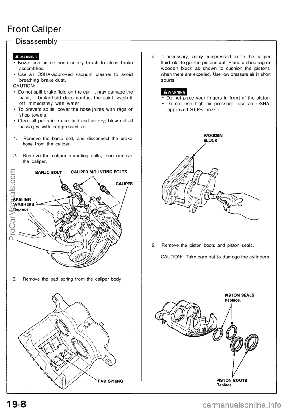
Front Calipe r
Disassembl y
• Neve r us e a n ai r hos e o r dr y brus h t o clea n brak e
assemblies .
• Us e a n OSHA-approve d vacuu m cleane r t o avoi d
breathin g brak e dust .
CAUTION :
• D o no t spil l brak e flui d o n th e car ; i t ma y damag e th e
paint ; i f brak e flui d doe s contac t th e paint , was h i t
of f immediatel y wit h water .
• T o preven t spills , cove r th e hos e joint s wit h rag s o r
sho p towels .
• Clea n al l part s i n brak e flui d an d ai r dry ; blo w ou t al l
passage s wit h compresse d air .
1 . Remov e th e banj o bolt , an d disconnec t th e brak e
hos e fro m th e caliper .
2. Remov e th e calipe r mountin g bolts , the n remov e
the caliper .
3 . Remov e th e pa d sprin g fro m th e calipe r body . 4
. I f necessary , appl y compresse d ai r t o th e calipe r
fluid inle t t o ge t th e piston s out . Plac e a sho p ra g o r
woode n bloc k a s show n t o cushio n th e piston s
when ther e ar e expelled . Us e lo w pressur e ai r i n shor t
spurts .
• D o no t plac e you r finger s i n fron t o f th e piston .
• D o no t us e hig h ai r pressure ; us e a n OSHA -
approve d 3 0 PS I nozzle .
5 . Remov e th e pisto n boot s an d pisto n seals .
CAUTION : Tak e car e no t t o damag e th e cylinders .
ProCarManuals.com
Page 498 of 1640
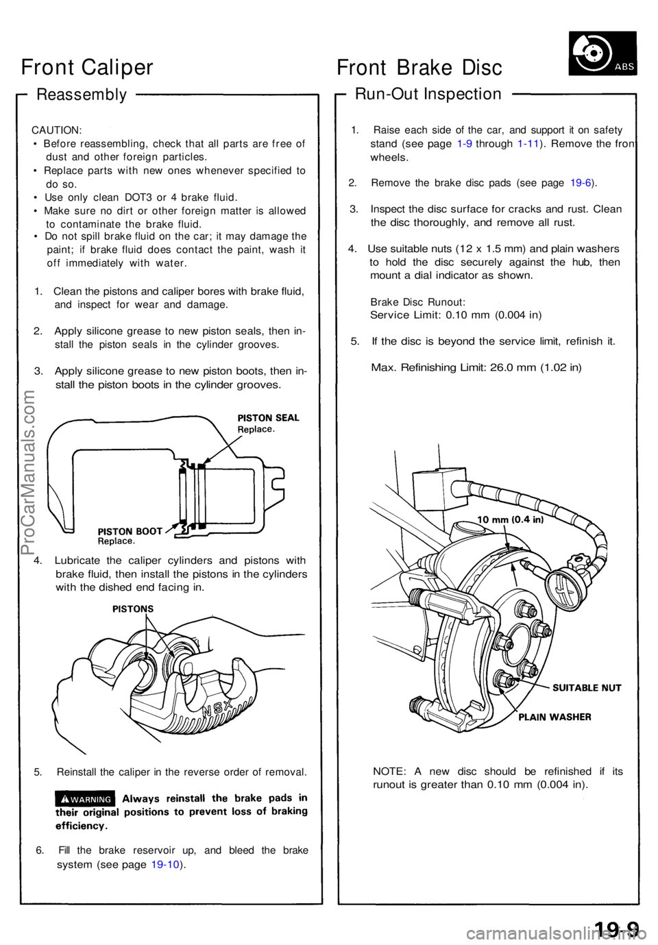
Reassembly
CAUTION:
• Befor e reassembling , chec k tha t al l part s ar e fre e o f
dus t an d othe r foreig n particles .
• Replac e part s wit h ne w one s wheneve r specifie d t o
do so .
• Us e onl y clea n DOT 3 o r 4 brak e fluid .
• Mak e sur e n o dir t o r othe r foreig n matte r i s allowe d
t o contaminat e th e brak e fluid .
• D o no t spil l brak e flui d o n th e car ; i t ma y damag e th e
paint ; i f brak e flui d doe s contac t th e paint , was h i t
of f immediatel y wit h water .
1. Clea n th e piston s an d calipe r bore s wit h brak e fluid ,
and inspec t fo r wea r an d damage .
2. Appl y silicon e greas e t o ne w pisto n seals , the n in -
stal l th e pisto n seal s i n th e cylinde r grooves .
3. Appl y silicon e greas e t o ne w pisto n boots , the n in -
stal l th e pisto n boot s in th e cylinde r grooves .
4. Lubricat e th e calipe r cylinder s an d piston s wit h
brak e fluid , the n instal l th e piston s i n th e cylinder s
with th e dishe d en d facin g in .
5. Reinstal l th e calipe r i n th e revers e orde r o f removal .
6 . Fil l th e brak e reservoi r up , an d blee d th e brak e
system (se e pag e 19-10 ).
NOTE : A ne w dis c shoul d b e refinishe d i f it s
runou t i s greate r tha n 0.1 0 m m (0.00 4 in) .
Fron t Brak e Dis c
Run-Ou t Inspectio n
1. Rais e eac h sid e o f th e car , an d suppor t i t o n safet y
stand (se e pag e 1-9 throug h 1-11 ). Remov e th e fron t
wheels .
2. Remov e th e brak e dis c pad s (se e pag e 19-6 ).
3 . Inspec t th e dis c surfac e fo r crack s an d rust . Clea n
the dis c thoroughly , an d remov e al l rust .
4. Us e suitabl e nut s (1 2 x 1. 5 mm ) an d plai n washer s
to hol d th e dis c securel y agains t th e hub , the n
moun t a dia l indicato r a s shown .
Brake Dis c Runout :
Service Limit : 0.1 0 m m (0.00 4 in )
5. I f th e dis c i s beyon d th e servic e limit , refinis h it .
Max . Refinishin g Limit : 26. 0 m m (1.0 2 in )
Front Caliper
ProCarManuals.com
Page 506 of 1640
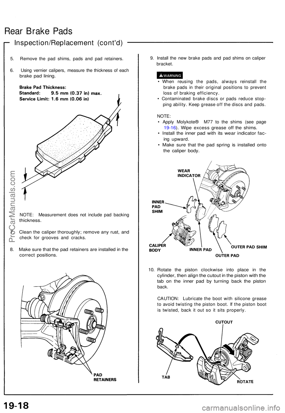
Rear Brak e Pad s
Inspection/Replacemen t (cont'd )
5. Remov e th e pa d shims , pad s an d pa d retainers .
6 . Usin g vernie r calipers , measur e th e thicknes s o f eac h
brak e pa d lining .
NOTE : Measuremen t doe s no t includ e pa d backin g
thickness .
7. Clea n th e calipe r thoroughly ; remov e an y rust , an d
chec k fo r groove s an d cracks .
8. Mak e sur e tha t th e pa d retainer s ar e installe d in th e
correc t positions .
9. Instal l th e ne w brak e pad s an d pa d shim s o n calipe r
bracket .
• Whe n reusin g th e pads , alway s reinstal l th e
brak e pad s i n thei r origina l position s t o preven t
los s o f brakin g efficiency .
• Contaminate d brak e disc s o r pad s reduc e stop -
pin g ability . Kee p greas e of f th e disc s an d pads .
NOTE :
• Appl y Molykote ® M7 7 t o th e shim s (se e pag e
19-16 ). Wip e exces s greas e of f th e shims .
• Instal l th e inne r pa d wit h it s wea r indicato r fac -
ing upward .
• Mak e sur e tha t th e pa d sprin g i s installe d ont o
the calipe r body .
10. Rotat e th e pisto n clockwis e int o plac e i n th e
cylinder , the n alig n th e cutou t i n th e pisto n wit h th e
tab o n th e inne r pa d b y turnin g bac k th e pisto n
back.
CAUTION : Lubricat e th e boo t wit h silicon e greas e
t o avoi d twistin g th e pisto n boot . I f th e pisto n boo t
i s twisted , bac k i t ou t s o i t sit s properly .
ProCarManuals.com
Page 511 of 1640

Rear Calipe r
Disassembl y (cont'd )
12. Remov e th e adjustin g bolt .
13. Remov e th e sprin g cover , adjustin g sprin g B ,
spacer , bearin g A an d cu p fro m th e adjustin g bolt .
14. Remov e th e sleev e piston , an d remov e th e pi n fro m
the cam .
1 5 . Remov e th e retur n spring .
16. Remov e th e parkin g leve r an d ca m a s a n assembl y
from th e calipe r body .
CAUTION : D o no t loose n th e parkin g nu t wit h th e
ca m installe d i n th e calipe r body . I f th e leve r an d
shaf t mus t b e separated , hol d th e leve r i n a vis e
an d loose n th e parkin g nut .
17. Remov e th e ca m boot .
ProCarManuals.com
Page 514 of 1640
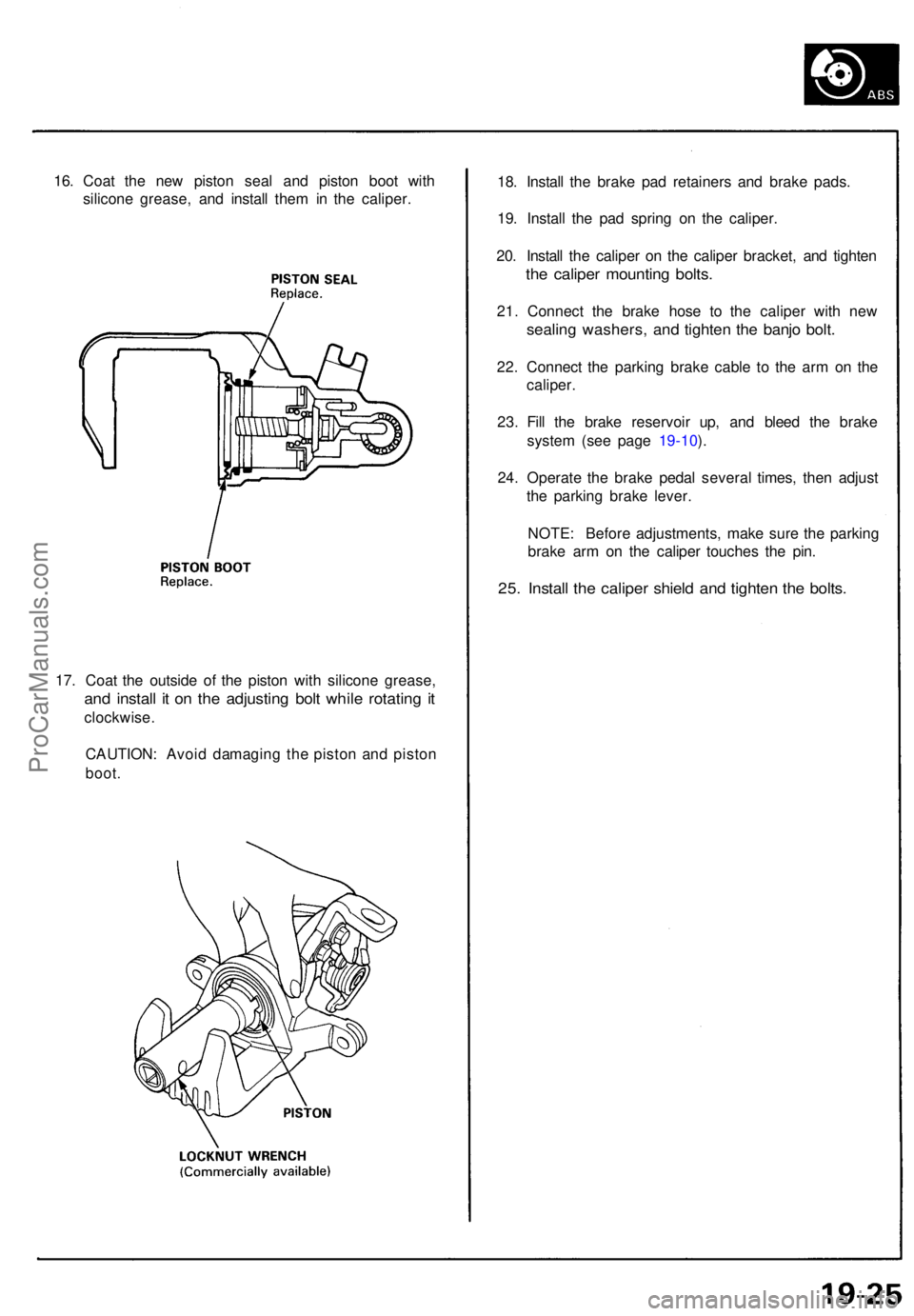
16. Coa t th e ne w pisto n sea l an d pisto n boo t wit h
silicon e grease , an d instal l the m in th e caliper .
17 . Coa t th e outsid e of the pisto n wit h silicon e grease ,
and instal l i t o n th e adjustin g bol t whil e rotatin g i t
clockwise .
CAUTION : Avoi d damagin g th e pisto n an d pisto n
boot.
18. Instal l th e brak e pa d retainer s an d brak e pads .
19 . Instal l th e pa d sprin g o n th e caliper .
20 . Instal l th e calipe r o n th e calipe r bracket , an d tighte n
the calipe r mountin g bolts .
21. Connec t th e brak e hos e t o th e calipe r wit h ne w
sealin g washers , an d tighte n th e banj o bolt .
22. Connec t th e parkin g brak e cabl e t o th e ar m o n th e
caliper .
23 . Fil l th e brak e reservoi r up , an d blee d th e brak e
syste m (se e pag e 19-10 ).
24 . Operat e th e brak e peda l severa l times , the n adjus t
th e parkin g brak e lever .
NOTE : Befor e adjustments , mak e sur e th e parkin g
brak e ar m o n th e calipe r touche s th e pin .
25. Instal l th e calipe r shiel d an d tighte n th e bolts .
ProCarManuals.com
Page 973 of 1640
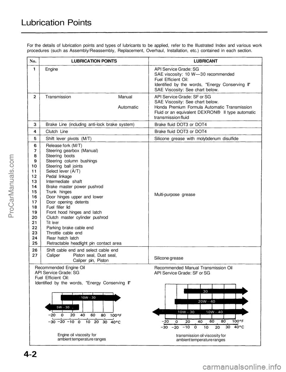
Lubrication Points
For the details of lubrication points and types of lubricants to be applied, refer to the Illustrated Index and various workprocedures (such as Assembly/Reassembly, Replacement, Overhaul, Installation, etc.) contained in each section.
No.
LUBRICATION POINTS
LUBRICANT
Engine
Transmission
Manual
Automatic
Brake Line (including anti-lock brake system)
Clutch Line Shift lever pivots (M/T)Release fork (M/T)Steering gearbox (Manual)
Steering boots Steering column bushings
Steering ball jointsSelect lever (A/T)
Pedal linkage Intermediate shaft
Brake master power pushrod
Trunk hinges Door hinges upper and lower
Door opening detents
Fuel filler lid
Front hood hinges and latch
Clutch master cylinder pushrod
Tilt lever
Parking brake cable end
Throttle cable end Rear hatch latchRetractable headlight pin contact area
Shift cable end and select cable end
Caliper Piston seal, Dust seal, Caliper pin, Piston
Recommended Engine Oil
API Service Grade: SG Fuel Efficient Oil:
Identified by the words, "Energy Conserving II" API Service Grade: SG
SAE viscosity: 10 W—30 recommended
Fuel Efficient Oil:
Identified by the words, "Energy Conserving II"
SAE Viscosity: See chart below.
API Service Grade: SF or SG SAE Viscosity: See chart below.
Honda Premium Formula Automatic Transmission
Fluid or an equivalent DEXRON® II type automatic
transmission fluid
Brake fluid DOT3 or DOT4
Brake fluid DOT3 or DOT4
Silicone grease with molybdenum disulfide
Multi-purpose grease
Silicone grease Recommended Manual Transmission Oil
API Service Grade: SF or SG
transmission oil viscosity forambient temperature ranges
Engine oil viscosity for
ambient temperature rangesProCarManuals.com
Page 1294 of 1640
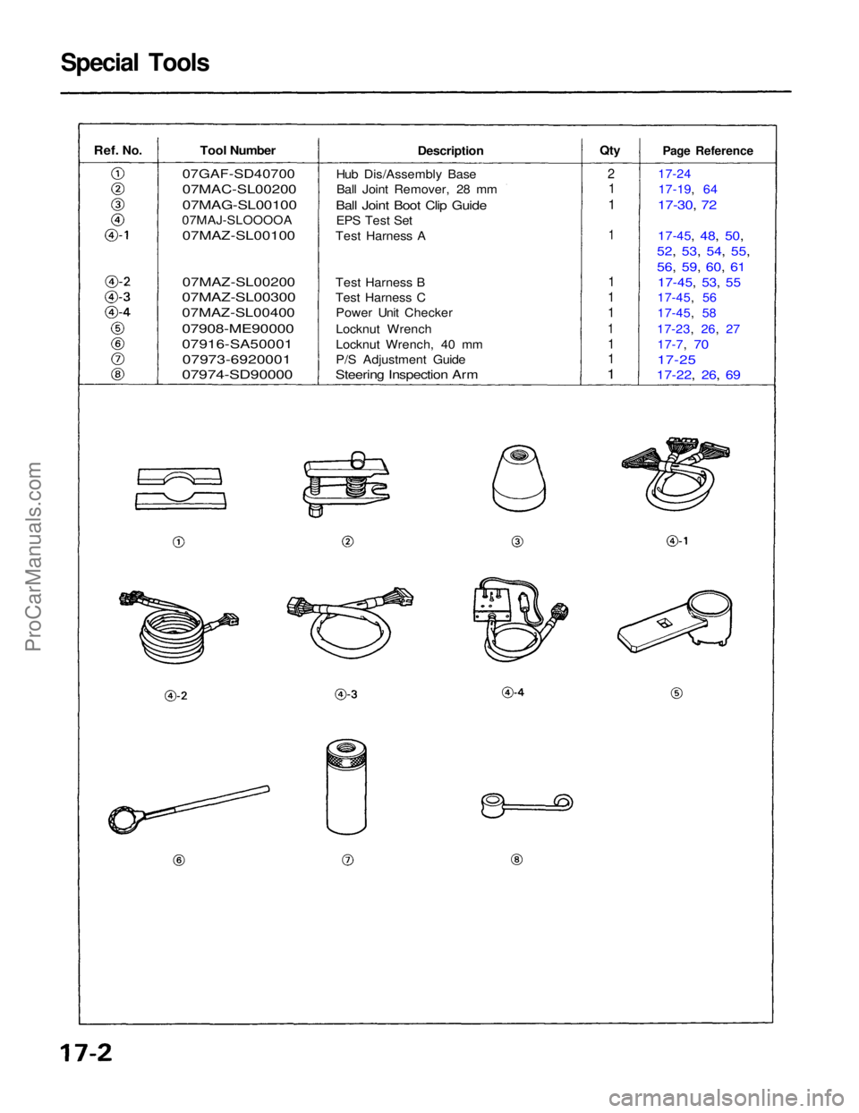
Special Tools
Ref.
No.
Tool Number
07GAF-SD40700
07MAC-SL00200
07MAG-SL00100
07MAJ-SLOOOOA
07MAZ-SL00100
07MAZ-SL00200
07MAZ-SL00300
07MAZ-SL00400
07908-ME90000
07916-SA50001
07973-6920001
07974-SD90000
Description
Hub Dis/Assembly Base Ball Joint Remover, 28 mm
Ball Joint Boot Clip Guide
EPS Test Set
Test Harness A
Test Harness B
Test Harness C Power Unit Checker
Locknut Wrench
Locknut Wrench, 40 mm
P/S Adjustment Guide
Steering Inspection Arm
Qty
2
1
1
1
1
1
1
1
1
1
1
Page Reference
17-24 17-19, 64
17-30, 72
1
7-45,
48, 50,
52, 53, 54, 55,
56, 59, 60, 61
17-45, 53, 55
17-45, 56
17-45, 58
17-23, 26, 27 17-7,
70
17-25
17-22, 26, 69ProCarManuals.com
Page 1312 of 1640
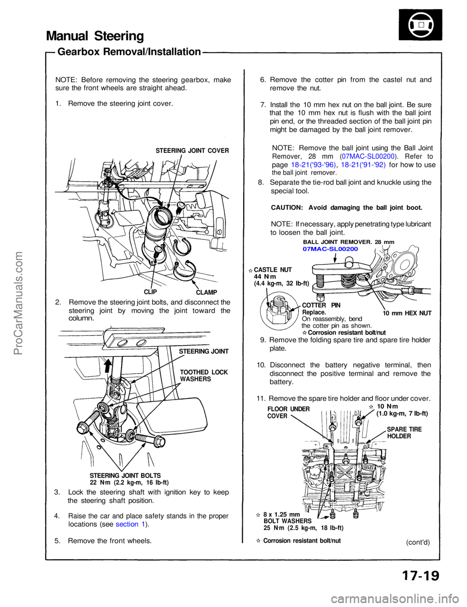
Manual Steering
Gearbox Removal/Installation
NOTE: Before removing the steering gearbox, make
sure the front wheels are straight ahead.
1. Remove the steering joint cover.
STEERING JOINT COVER
CLAMP
CLIP
2. Remove the steering joint bolts, and disconnect the steering joint by moving the joint toward the
column.
STEERING JOINT
STEERING JOINT BOLTS
22 N .
m (2.2 kg-m, 16 Ib-ft)
3. Lock the steering shaft with ignition key to keep the steering shaft position.
4. Raise the car and place safety stands in the proper
locations (see section 1).
5. Remove the front wheels.
8 x
1.25
mm
BOLT WASHERS
25 N .
m (2.5 kg-m, 18 Ib-ft)
Corrosion resistant bolt/nut
FLOOR UNDER
COVER
9. Remove the folding spare tire and spare tire holder
plate.
10. Disconnect the battery negative terminal, then disconnect the positive terminal and remove the
battery.
11. Remove the spare tire holder and floor under cover.
10 N·
m
(1.0 kg-m, 7 Ib-ft)
SPARE TIRE
HOLDER
(cont'd)
COTTER PIN
Replace.
On reassembly, bend
the cotter pin as shown.
Corrosion resistant bolt/nut
CASTLE NUT
44 N
·
m
(4.4 kg-m, 32 Ib-ft)
10 mm HEX NUT
NOTE: If necessary, apply penetrating type lubricant
to loosen the ball joint.
BALL JOINT REMOVER. 28 mm
07MAC-SL00200
6. Remove the cotter pin from the castel nut and
remove the nut.
7. Install the 10 mm hex nut on the ball joint. Be sure that the 10 mm hex nut is flush with the ball joint
pin end, or the threaded section of the ball joint pin
might be damaged by the ball joint remover.
NOTE: Remove the ball joint using the Ball Joint
Remover, 28 mm (07MAC-SL00200). Refer to
page 18-21('93-'96), 18-21('91-'92) for how to use
8. Separate the tie-rod ball joint and knuckle using the special tool.
CAUTION: Avoid damaging the ball joint boot.
TOOTHED LOCK
WASHERSProCarManuals.com
Page 1314 of 1640
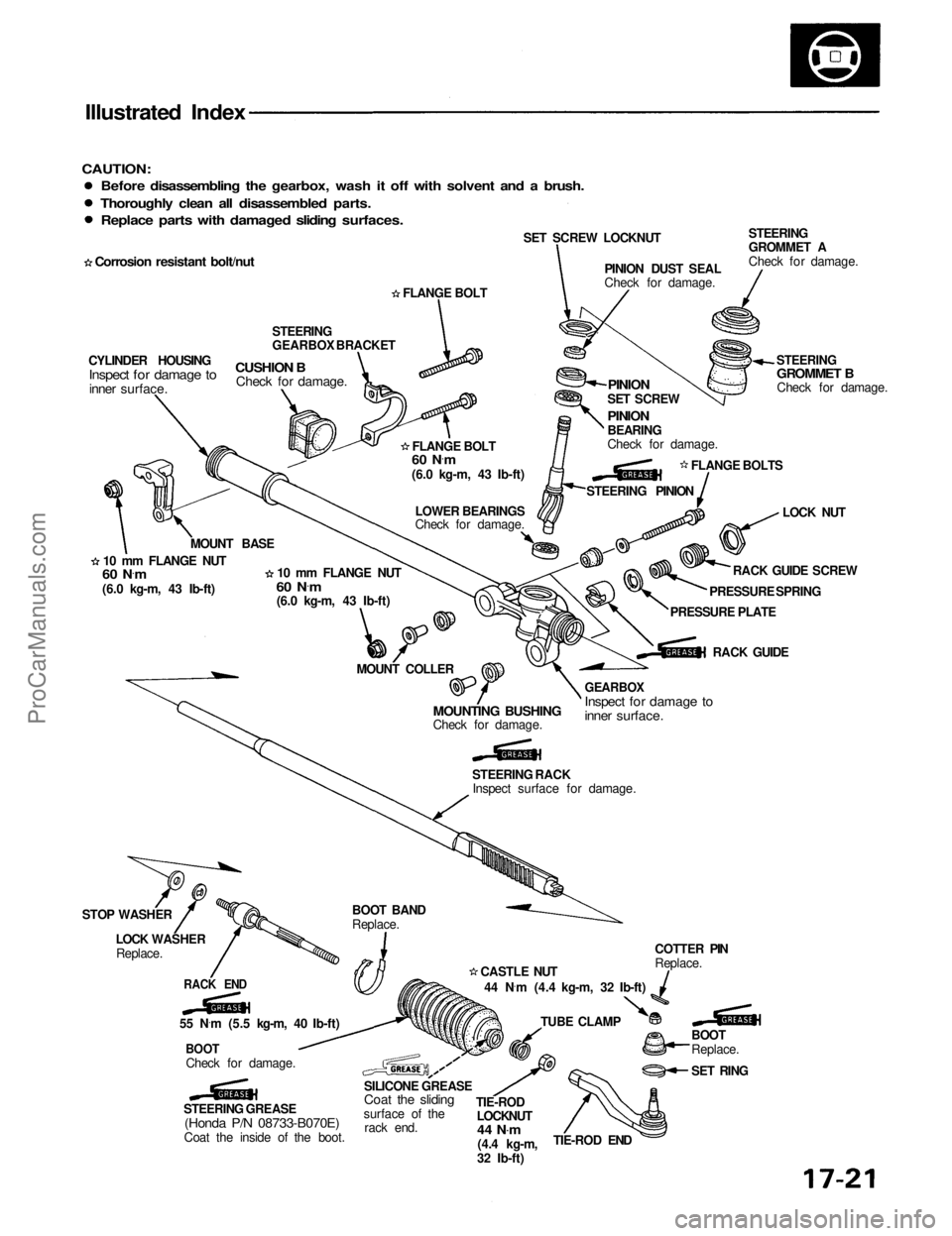
Illustrated Index
CAUTION:
Before disassembling the gearbox, wash it off with solvent and a brush.
Thoroughly clean all disassembled parts.
Replace parts with damaged sliding surfaces.
SET SCREW LOCKNUT
FLANGE BOLT PINION DUST SEAL
Check for damage.STEERING
GROMMET A
Check for damage.
STEERING
GROMMET B
Check for damage.
PINION
SET SCREW
PINION
BEARING
Check for damage.
FLANGE BOLTS
Corrosion resistant bolt/nut
CYLINDER HOUSING
Inspect for damage to
inner surface.
STEERING
GEARBOX BRACKET
CUSHION B
Check for damage.
FLANGE BOLT
60 N ·
m
(6.0 kg-m, 43 Ib-ft)
10 mm FLANGE NUT
60 N ·
m
(6.0 kg-m, 43 Ib-ft) MOUNT BASE
10 mm FLANGE NUT
60 N ·
m
(6.0 kg-m, 43 Ib-ft) LOWER BEARINGS
Check for damage.
STEERING PINION
LOCK NUT
RACK GUIDE SCREW
PRESSURE SPRING
PRESSURE PLATE
RACK GUIDE
GEARBOX
Inspect for damage to
inner surface.
MOUNT COLLER
MOUNTING BUSHING
Check for damage.
STEERING RACKInspect surface for damage.
BOOT BAND
Replace.
STOP WASHER
LOCK WASHERReplace.
RACK END
55 N ·
m (5.5 kg-m, 40 Ib-ft)
BOOT
Check for damage.
STEERING GREASE
(Honda P/N 08733-B070E)
Coat the inside of the boot. SILICONE GREASE
Coat the sliding
surface of the rack end. TIE-ROD
LOCKNUT
44 N .
m
(4.4 kg-m,
32 Ib-ft) TIE-ROD END BOOT
Replace.
SET RING
TUBE CLAMP COTTER PIN
Replace.
CASTLE NUT
44 N ·
m (4.4 kg-m, 32 Ib-ft)ProCarManuals.com