oil level ACURA NSX 1991 Service Repair Manual
[x] Cancel search | Manufacturer: ACURA, Model Year: 1991, Model line: NSX, Model: ACURA NSX 1991Pages: 1640, PDF Size: 60.48 MB
Page 33 of 1640
Maintenance
Transmissio n Oi l
NOTE : Chec k th e oi l a t norma l operatin g temperatur e
(the coolin g fa n come s on) , engin e OFF , an d th e ca r o n
leve l ground .
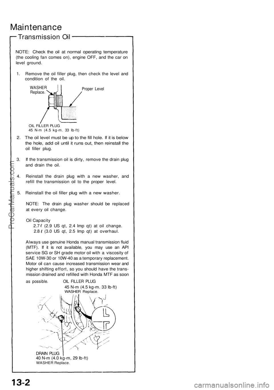
1 . Remov e th e oi l fille r plug , the n chec k th e leve l an d
conditio n o f th e oil .
WASHE RReplace .Proper Leve l
OIL FILLE R PLU G45 N- m (4. 5 kg-m . 3 3 Ib-ft )
2. Th e oi l leve l mus t b e u p to th e fil l hole . I f i t i s belo w
the hole , ad d oi l unti l i t run s out , the n reinstal l th e
oil fille r plug .
3 . I f th e transmissio n oi l i s dirty , remov e th e drai n plu g
an d drai n th e oil .
4 . Reinstal l th e drai n plu g wit h a ne w washer , an d
refil l th e transmissio n oi l t o th e prope r level .
5. Reinstal l th e oi l fille r plu g wit h a ne w washer .
NOTE: Th e drai n plu g washe r shoul d b e replace d
a t ever y oi l change .
Oi l Capacit y
2. 7 ( 2.9 U S qt , 2. 4 Im p qt ) a t oi l change .
2.8 (3. 0 U S qt , 2. 5 Im p qt ) a t overhaul .
Alway s us e genuin e Hond a manua l transmissio n flui d
(MTF) . I f i t i s no t available , yo u ma y us e a n AP I
servic e S G o r S H grad e moto r oi l wit h a viscosit y o f
SA E 10W-3 0 o r 10W-4 0 a s a temporar y replacement .
Moto r oi l ca n caus e increase d transmissio n wea r an d
highe r shiftin g effort , s o yo u shoul d hav e th e trans -
missio n draine d an d refille d wit h Hond a MT F a s soo n
as possible . OIL FILLE R PLU G
45 N- m (4. 5 kg-m . 3 3 Ib-ft )WASHE R Replace .
DRAIN PLU G40 N- m (4. 0 kg-m , 2 9 Ib-ft )WASHE R Replac e
ProCarManuals.com
Page 125 of 1640
Camshafts
Installation
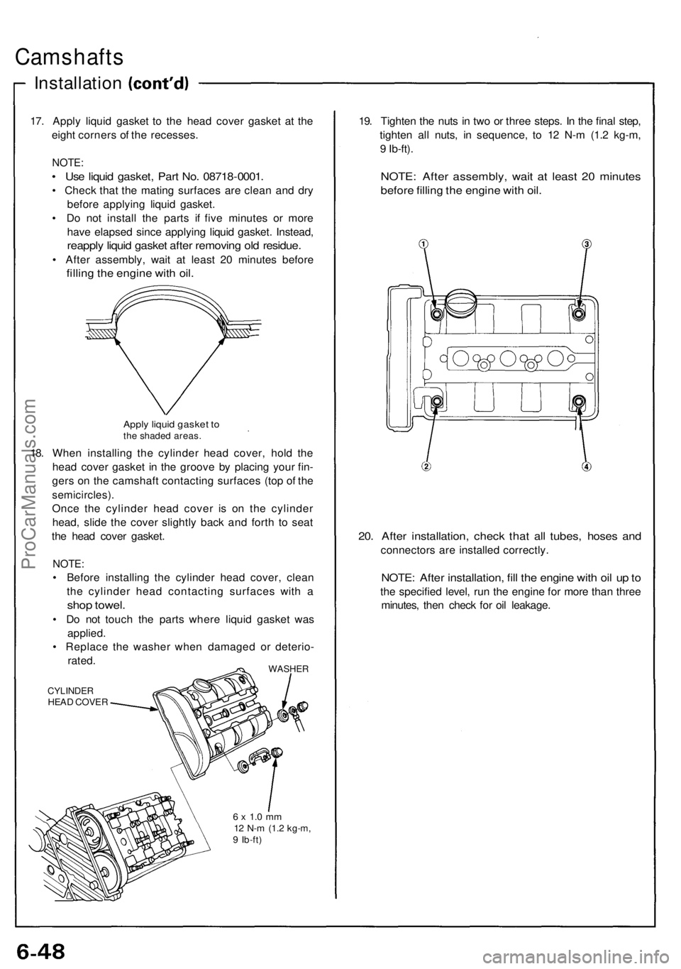
17. Appl y liqui d gaske t t o th e hea d cove r gaske t a t th e
eigh t corner s o f th e recesses .
NOTE:
• Us e liqui d gasket , Par t No . 0871 8-0001 .
• Chec k tha t th e matin g surface s ar e clea n an d dr y
befor e applyin g liqui d gasket .
• D o no t instal l th e part s i f fiv e minute s o r mor e
hav e elapse d sinc e applyin g liqui d gasket . Instead ,
reapply liqui d gaske t afte r removin g ol d residue .
• Afte r assembly , wai t a t leas t 2 0 minute s befor e
filling th e engin e wit h oil .
Appl y liqui d gaske t t oth e shade d areas .
18. Whe n installin g th e cylinde r hea d cover , hol d th e
hea d cove r gaske t i n th e groov e b y placin g you r fin -
ger s o n th e camshaf t contactin g surface s (to p o f th e
semicircles) .
Once th e cylinde r hea d cove r i s o n th e cylinde r
head , slid e th e cove r slightl y bac k an d fort h t o sea t
th e hea d cove r gasket .
NOTE:
• Befor e installin g th e cylinde r hea d cover , clea n
th e cylinde r hea d contactin g surface s wit h a
sho p towel .
• D o no t touc h th e part s wher e liqui d gaske t wa s
applied .
• Replac e th e washe r whe n damage d o r deterio -
rated .
WASHE R
CYLINDE RHEAD COVE R
6 x 1. 0 m m12 N- m (1. 2 kg-m ,9 Ib-ft )
19. Tighte n th e nut s i n tw o o r thre e steps . I n th e fina l step ,
tighte n al l nuts , i n sequence , t o 1 2 N- m (1. 2 kg-m ,
9 Ib-ft) .
NOTE : Afte r assembly , wai t a t leas t 2 0 minute s
before fillin g th e engin e wit h oil .
20. Afte r installation , chec k tha t al l tubes , hose s an d
connector s ar e installe d correctly .
NOTE: Afte r installation , fil l th e engin e wit h oi l u p to
th e specifie d level , ru n th e engin e fo r mor e tha n thre e
minutes , the n chec k fo r oi l leakage .
ProCarManuals.com
Page 149 of 1640
Engine Oil
Inspection
1. Check engine oil with the engine off and the car
parked on level ground.
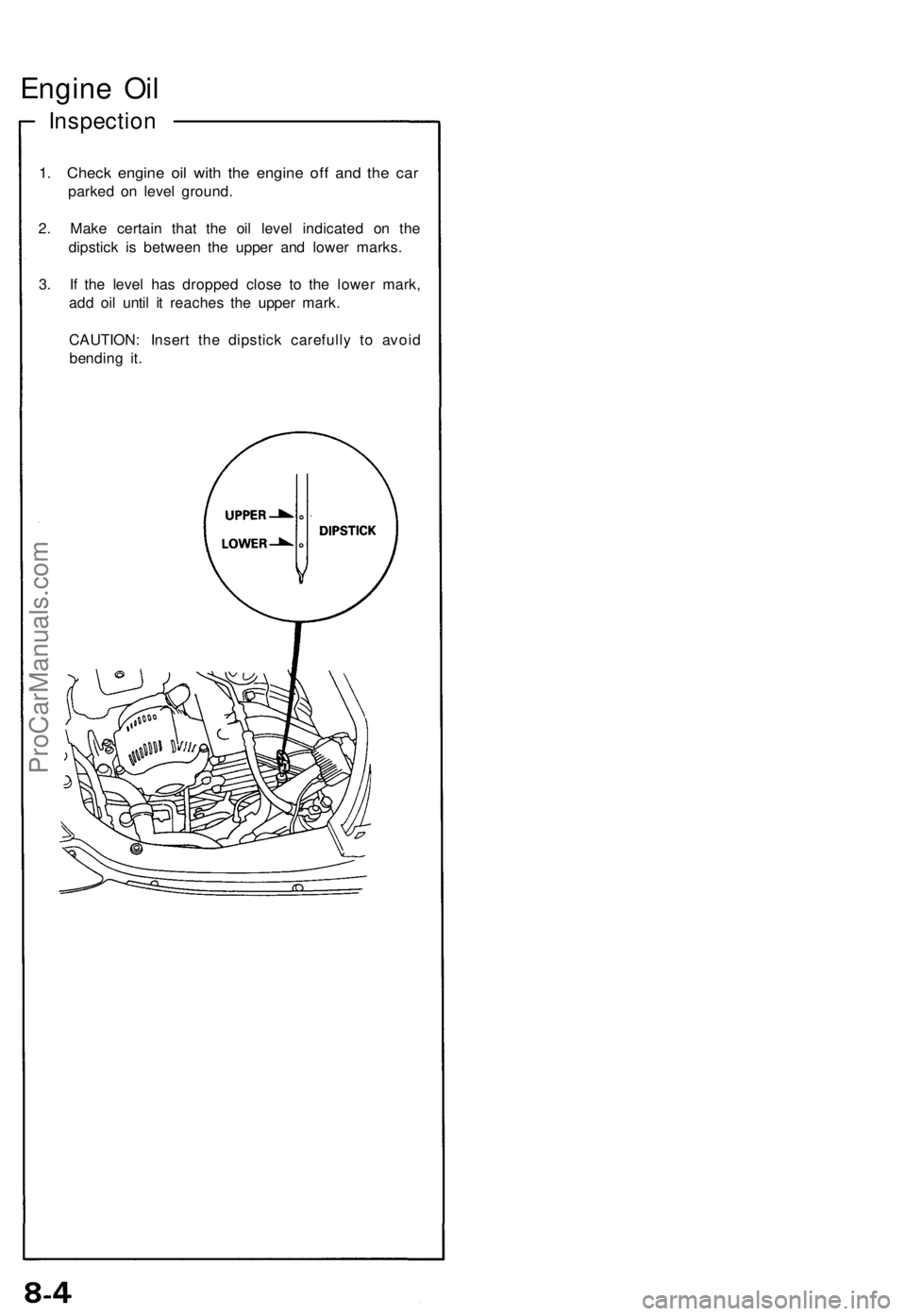
2. Make certain that the oil level indicated on the
dipstick is between the upper and lower marks.
3. If the level has dropped close to the lower mark,
add oil until it reaches the upper mark.
CAUTION: Insert the dipstick carefully to avoid
bending it.ProCarManuals.com
Page 151 of 1640
Oil Pressur e
Testing
If th e oi l pressur e warnin g ligh t stay s o n wit h th e engin e
running , chec k th e engin e oi l level . I f th e oi l leve l i s
correct :
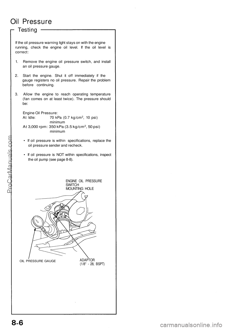
1 . Remov e th e engin e oi l pressur e switch , an d instal l
a n oi l pressur e gauge .
2. Star t th e engine . Shu t i t of f immediatel y i f th e
gaug e register s n o oi l pressure . Repai r th e proble m
befor e continuing .
3 . Allo w th e engin e t o reac h operatin g temperatur e
(fa n come s o n a t leas t twice) . Th e pressur e shoul d
be:
Engin e Oi l Pressure :
A t Idle : 7 0 kP a (0. 7 kg/cm2, 1 0 psi )
minimu m
At 3,00 0 rpm : 35 0 kP a (3. 5 kg/cm2, 5 0 psi )
minimu m
• I f oi l pressur e i s
within specifications , replac e th e
oi l pressur e sende r an d recheck .
• I f oi l pressur e i s NO T withi n specifications , inspec t
th e oi l pum p (se e pag e 8-8) .
ENGIN E OI L PRESSUR ESWITCHMOUNTIN G HOL E
OIL PRESSUR E GAUG E ADAPTO R
(1/8 " - 28 , BSPT )
ProCarManuals.com
Page 301 of 1640
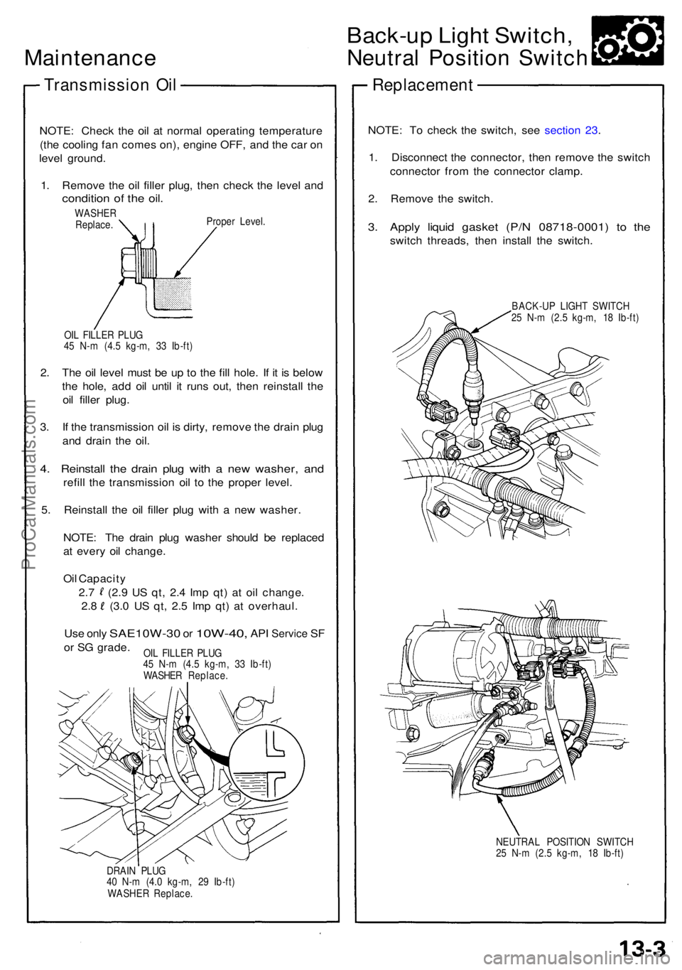
Maintenance
Transmissio n Oi l
NOTE : Chec k th e oi l a t norma l operatin g temperatur e
(th e coolin g fa n come s on) , engin e OFF , an d th e ca r o n
leve l ground .
1 . Remov e th e oi l fille r plug , the n chec k th e leve l an d
conditio n o f th e oil .
WASHE R
Replace . Prope
r Level .
OI L FILLE R PLU G
4 5 N- m (4. 5 kg-m , 3 3 Ib-ft )
2. Th e oi l leve l mus t b e u p t o th e fill hole . I f i t i s belo w
th e hole , ad d oi l unti l i t run s out , the n reinstal l th e
oi l fille r plug .
3 . I f th e transmissio n oi l i s dirty , remov e th e drai n plu g
an d drai n th e oil .
4. Reinstal l th e drai n plu g wit h a ne w washer , an d
refil l th e transmissio n oi l t o th e prope r level .
5 . Reinstal l th e oi l fille r plu g wit h a ne w washer .
NOTE : Th e drai n plu g washe r shoul d b e replace d
a t ever y oi l change .
Oi l Capacity
2. 7 (2. 9 U S qt , 2. 4 Im p qt ) a t oi l change .
2.8 (3. 0 U S qt , 2. 5 Im p qt ) a t overhaul .
Use onl y SAE10W-3 0 or 10W-40 , API Servic e SF
or S G grade .
DRAIN PLU G
4 0 N- m (4. 0 kg-m , 2 9 Ib-ft )
WASHE R Replace .
Back-up Ligh t Switch ,
Neutral Positio n Switc h
Replacemen t
NOTE: T o chec k th e switch , se e sectio n 23 .
1 . Disconnec t th e connector , the n remov e th e switc h
connecto r fro m th e connecto r clamp .
2 . Remov e th e switch .
3. Appl y liqui d gaske t (P/ N 08718-0001 ) t o th e
switc h threads , the n instal l th e switch .
BACK-U P LIGH T SWITC H
2 5 N- m (2. 5 kg-m , 1 8 Ib-ft )
NEUTRA L POSITIO N SWITC H
2 5 N- m (2. 5 kg-m , 1 8 Ib-ft )
OI
L FILLE R PLU G
4 5 N- m (4. 5 kg-m , 3 3 Ib-ft )
WASHE R Replace .
ProCarManuals.com
Page 966 of 1640
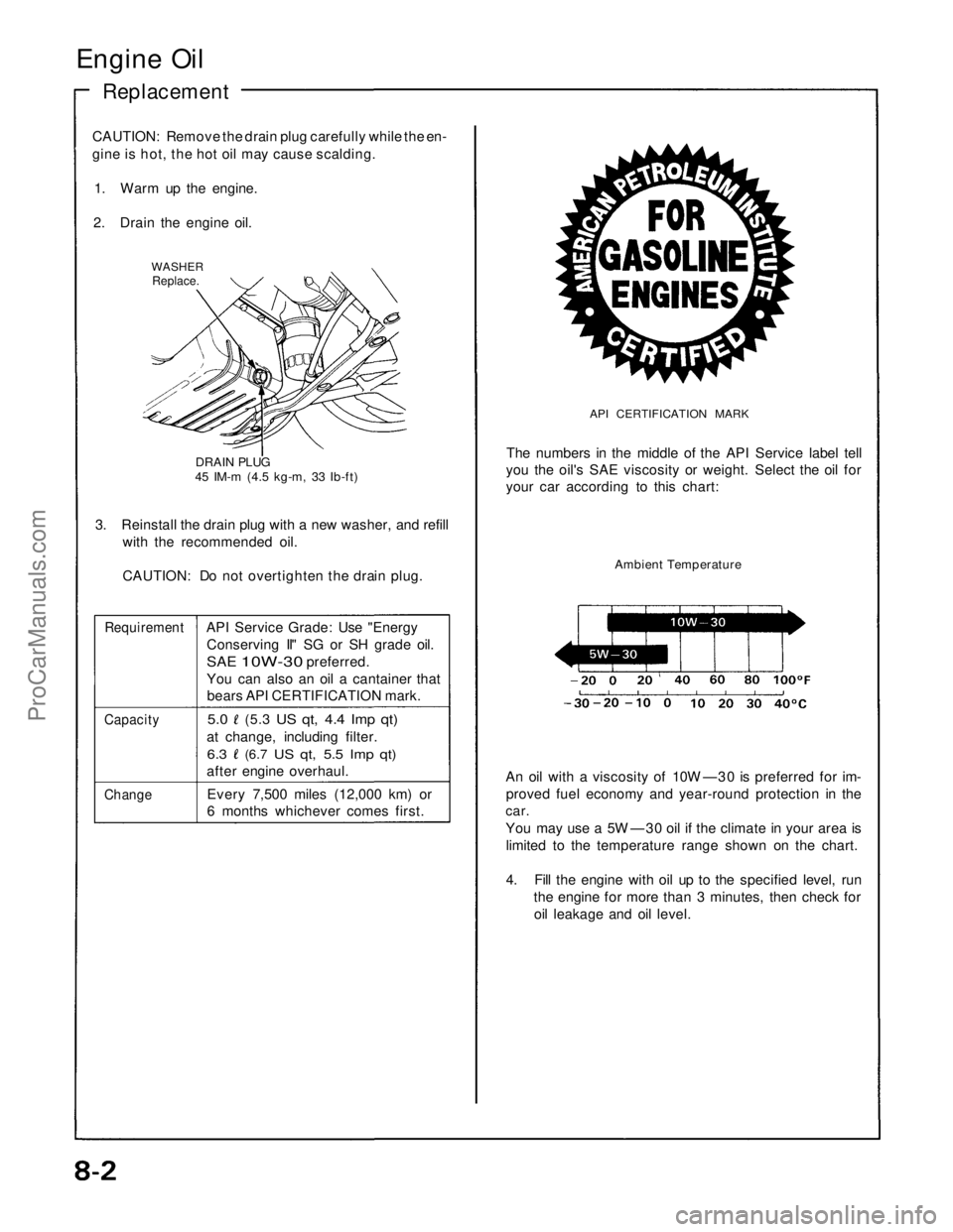
Engine Oil
Replacement
CAUTION: Remove the drain plug carefully while the en-
gine is hot, the hot oil may cause scalding.
1. Warm up the engine.
2. Drain the engine oil.
WASHER
Replace.
DRAIN PLUG
45 IM-m (4.5 kg-m, 33 Ib-ft)
3. Reinstall the drain plug with a new washer, and refill
with the recommended oil.
CAUTION: Do not overtighten the drain plug.
Requirement
API Service Grade: Use "Energy
Conserving II" SG or SH grade oil.
SAE
10W-30
preferred.
You can also an oil a cantainer that
bears API CERTIFICATION mark.
Capacity
5.0
(5.3
US qt, 4.4 Imp qt)
at change, including filter.
6.3
(6.7
US qt, 5.5 Imp qt)
after engine overhaul.
Change
Every 7,500 miles (12,000 km) or
6 months whichever comes first.
API CERTIFICATION MARK
The numbers in the middle of the API Service label tell
you the oil's SAE viscosity or weight. Select the oil for
your car according to this chart:
Ambient Temperature
An oil with a viscosity of 10W —30 is preferred for im-
proved fuel economy and year-round protection in the
car.
You may use a 5W —30 oil if the climate in your area is
limited to the temperature range shown on the chart.
4. Fill the engine with oil up to the specified level, run
the engine for more than 3 minutes, then check for
oil leakage and oil level.ProCarManuals.com
Page 975 of 1640
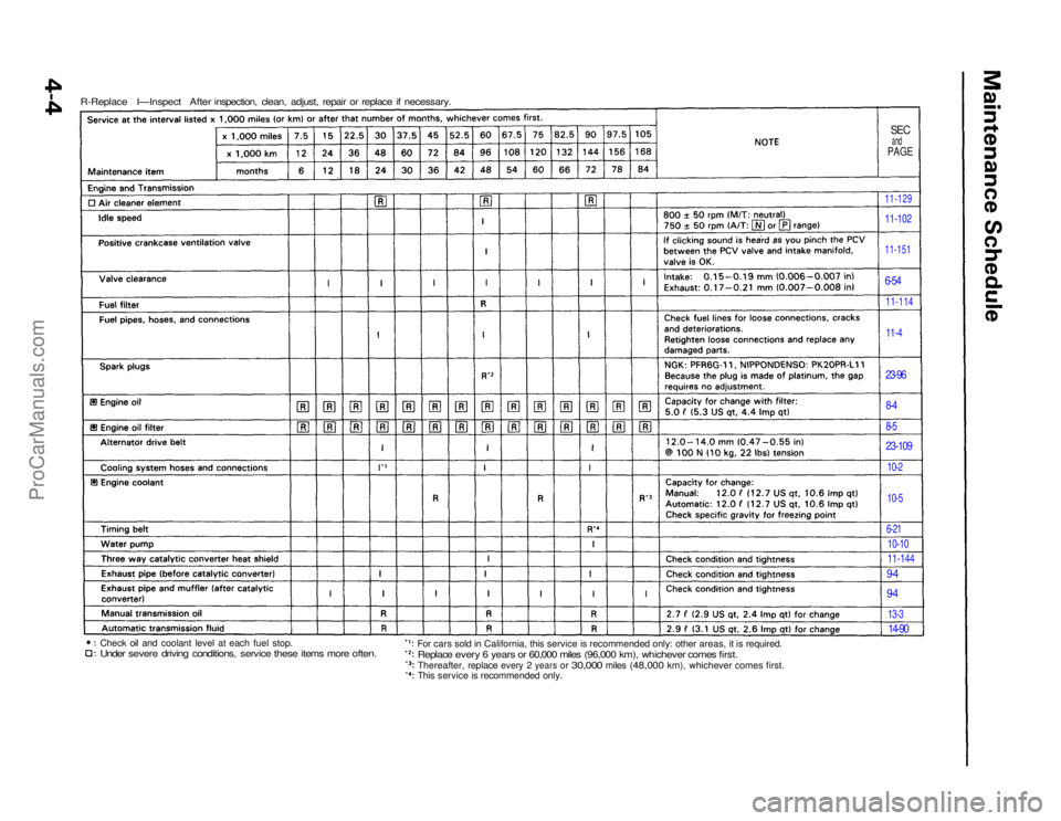
R-Replace I—Inspect After inspection, clean, adjust, repair or replace if necessary.
SEC
and
PAGE
11-129
11-102
11-151
6-54
11-114
11-4
23-96
8-4
8-5
23-109
10-2
10-5
6-21
10-10
11-144
9-4
9-4
13-3
14-90
For cars sold in California, this service is recommended only: other areas, it is required.
Replace every 6 years or 60,000 miles (96,000 km), whichever comes first.
Thereafter, replace
every
2
years
or
30,000
miles
(48,000
km), whichever comes first.
This service is recommended only.
Check oil and coolant level at each fuel stop.
Under severe driving conditions, service these items more often.ProCarManuals.com
Page 1002 of 1640
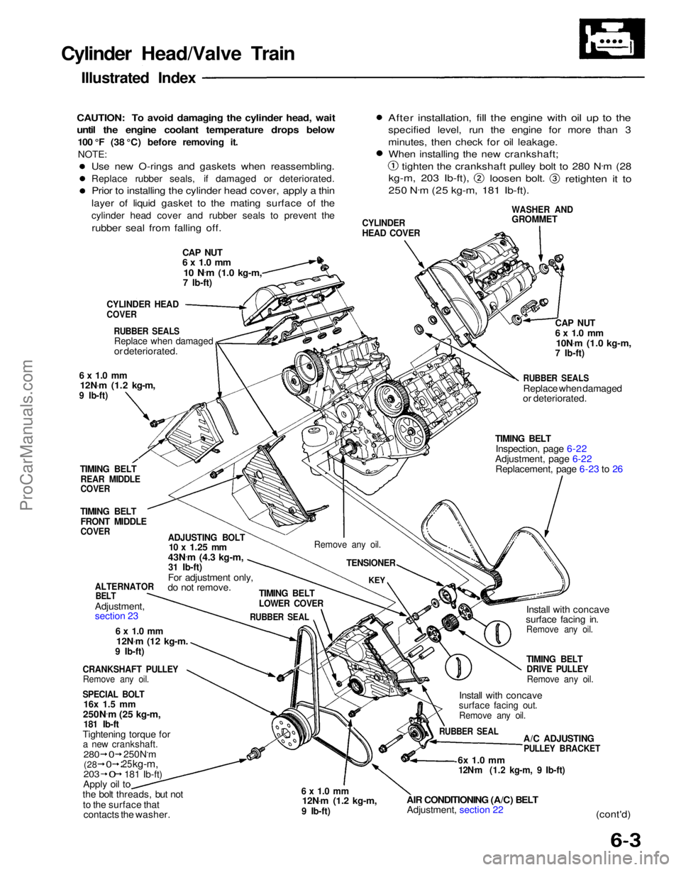
Cylinder Head/Valve Train
Illustrated Index
CAUTION: To avoid damaging the cylinder head, wait
until the engine coolant temperature drops below
100 °F (38 °C) before removing it.NOTE:
CAP NUT
6 x 1.0 mm
10 N .
m
(1.0 kg-m,
7 Ib-ft)
CYLINDER
HEAD COVER
WASHER AND
GROMMET
After installation, fill the engine with oil up to the
specified level, run the engine for more than 3
minutes, then check for oil leakage.
When installing the new crankshaft;
tighten the crankshaft pulley bolt to 280 N .
m (28
kg-m, 203 Ib-ft),
loosen bolt.
retighten it to
250 N .
m (25 kg-m, 181 Ib-ft).
CYLINDER HEAD
COVER
RUBBER SEALS
Replace when damaged
or deteriorated.
6 x 1.0 mm
12N .
m (1.2 kg-m,
9 Ib-ft)
TIMING BELT
REAR MIDDLE
COVER
TIMING BELT
FRONT MIDDLE
COVER
ADJUSTING BOLT
10 x
1.25
mm
43N .
m (4.3 kg-m,
31 Ib-ft)
For adjustment only,
do not remove.
ALTERNATOR
BELT
Adjustment,
section 23
6 x 1.0 mm
12N .
m
(12
kg-m.
9 Ib-ft)
CRANKSHAFT PULLEY
Remove any oil.
SPECIAL BOLT
16x 1.5 mm
250N .
m (25 kg-m,
181 Ib-ft
Tightening torque for
a new crankshaft.
203
Apply oil to
the bolt threads, but not
to the surface that contacts the washer.
6 x 1.0 mm
12N .
m (1.2 kg-m,
9 Ib-ft)
AIR CONDITIONING (A/C) BELT
Adjustment, section 22
6x 1.0 mm
12N .
m (1.2 kg-m, 9 Ib-ft)
(cont'd)
A/C ADJUSTING
PULLEY BRACKET
RUBBER SEAL
Install with concave
surface facing out.
Remove any oil.
TIMING BELT
DRIVE PULLEY
Remove any oil.
Install with concave
surface facing in.
Remove any oil.
TIMING BELT
Inspection, page 6-22
Adjustment, page 6-22 Replacement, page 6-23 to 26
RUBBER SEALS
Replace when damaged
or deteriorated.
CAP NUT
6 x 1.0 mm
10N .
m (1.0 kg-m,
7 Ib-ft)
TIMING BELT
LOWER COVER
RUBBER SEAL
KEY
Remove any oil.
TENSIONER
280
250N.m
25
kg-m,
181 Ib-ft)
(28
0
0
0
Use new O-rings and gaskets when reassembling.
Replace rubber seals, if damaged or deteriorated.
Prior to installing the cylinder head cover, apply a thin
layer of liquid gasket to the mating surface of the
cylinder head cover and rubber seals to prevent the
rubber seal from falling off.ProCarManuals.com
Page 1007 of 1640
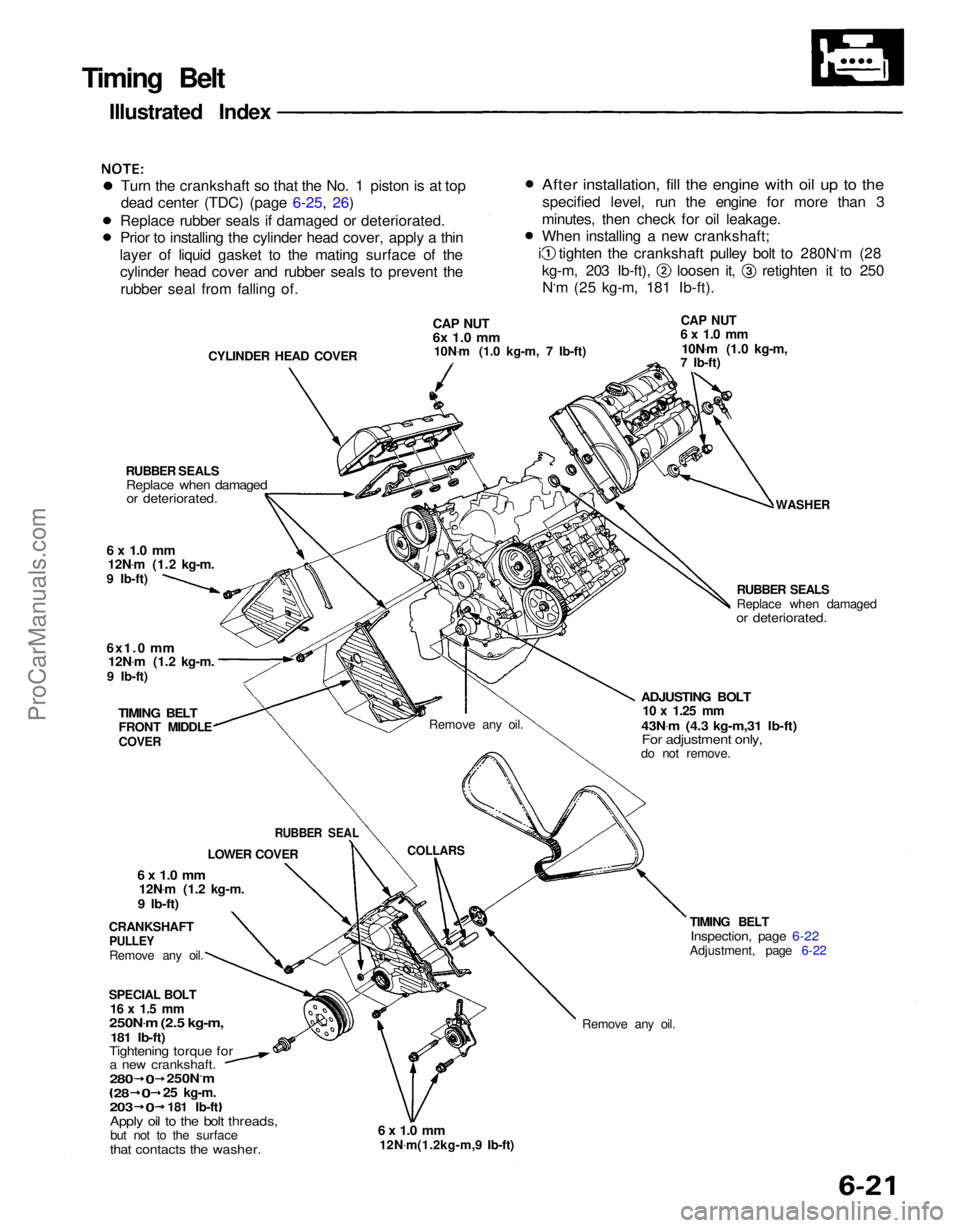
Remove any oil.
TIMING BELT
Inspection, page 6-22
Adjustment, page 6-22
6 x 1.0 mm
12N .
m(1.2kg-m,9 Ib-ft)
Timing Belt
Illustrated Index
Turn the crankshaft so that the No. 1 piston is at top
dead center (TDC) (page 6-25, 26)
Replace rubber seals if damaged or deteriorated.
Prior to installing the cylinder head cover, apply a thin
layer of liquid gasket to the mating surface of the cylinder head cover and rubber seals to prevent the
rubber seal from falling of.
CYLINDER HEAD COVER
CAP NUT
6x 1.0 mm
10N .
m (1.0 kg-m, 7 Ib-ft)
CAP NUT
6 x 1.0 mm
10N .
m (1.0 kg-m,
7 Ib-ft)
WASHER
RUBBER SEALS
Replace when damaged
or deteriorated.
ADJUSTING BOLT
10 x
1.25
mm
43N .
m (4.3 kg-m,31 Ib-ft)
For adjustment only,
do not remove.
Remove any oil.
COLLARS
RUBBER SEALS
Replace when damaged
or deteriorated.
6 x 1.0 mm
12N .
m (1.2 kg-m.
9 Ib-ft)
6x1.0
mm
12N .
m (1.2 kg-m.
9 Ib-ft)
TIMING BELT
FRONT MIDDLE
COVER
CRANKSHAFT
PULLEY
Remove any oil.
6 x 1.0 mm
12N .
m (1.2 kg-m.
9 Ib-ft)
SPECIAL BOLT
16 x 1.5 mm
250N .
m (2.5 kg-m,
181 Ib-ft)
Tightening torque for
a new crankshaft.
Apply oil to the bolt threads,
but not to the surface
that contacts the washer.
280
0
250N.m
28
0
25
kg-m.
203
0
181 Ib-ft LOWER COVER
RUBBER SEAL
After installation, fill the engine with oil up to the
specified level, run the engine for more than 3
minutes, then check for oil leakage.
When installing a new crankshaft; i tighten the crankshaft pulley bolt to 280N.m (28
kg-m, 203 Ib-ft), loosen it, retighten it to 250
N.m (25 kg-m, 181 Ib-ft).ProCarManuals.com
Page 1012 of 1640
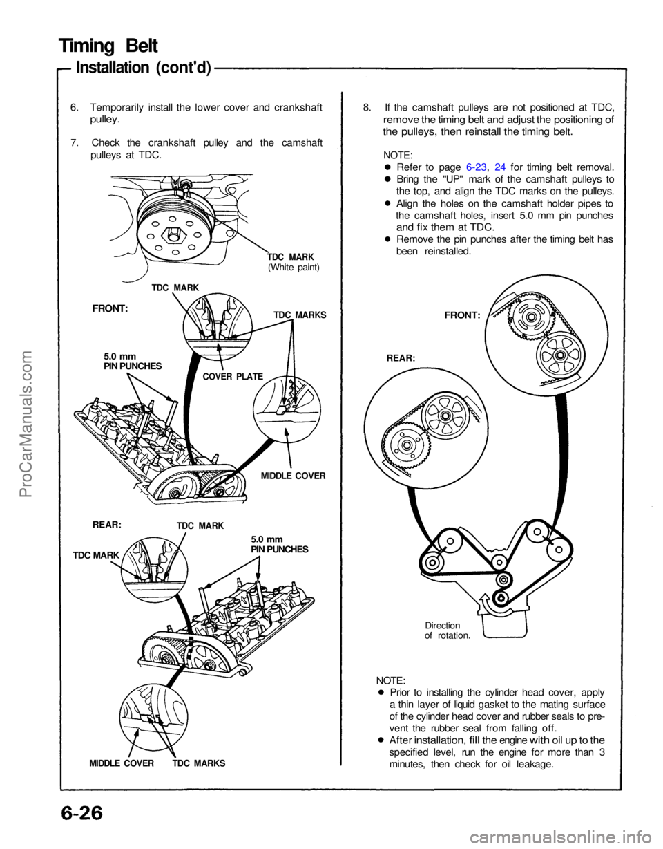
Prior to installing the cylinder head cover, apply
a thin layer of liquid gasket to the mating surface
of the cylinder head cover and rubber seals to pre-
vent the rubber seal from falling off.
After
installation,
fill
the
engine
with
oil up to the
specified level, run the engine for more than 3 minutes, then check for oil leakage.
8. If the camshaft pulleys are not positioned at TDC,
remove the timing belt and adjust the positioning of
the pulleys, then reinstall the timing belt.
6. Temporarily install the lower cover and crankshaft
pulley.
7. Check the crankshaft pulley and the camshaft pulleys at TDC.
FRONT:
5.0 mm
PIN PUNCHES
MIDDLE COVER
REAR:
TDC MARK
5.0 mm
PIN PUNCHES
Direction
of rotation.
FRONT:
REAR:
TDC MARK
TDC MARK
(White paint)
TDC MARKS
COVER PLATE
TDC MARK
MIDDLE COVER TDC MARKS
Timing Belt
Installation (cont'd)
Refer to page 6-23, 24 for timing belt removal.
Bring the "UP" mark of the camshaft pulleys to
the top, and align the TDC marks on the pulleys.
Align the holes on the camshaft holder pipes to
the camshaft holes, insert 5.0 mm pin punches
and fix them at TDC.
Remove the pin punches after the timing belt has
been reinstalled.
NOTE:
NOTE:ProCarManuals.com