fuse ACURA NSX 1991 Service Owner's Manual
[x] Cancel search | Manufacturer: ACURA, Model Year: 1991, Model line: NSX, Model: ACURA NSX 1991Pages: 1640, PDF Size: 60.48 MB
Page 546 of 1640
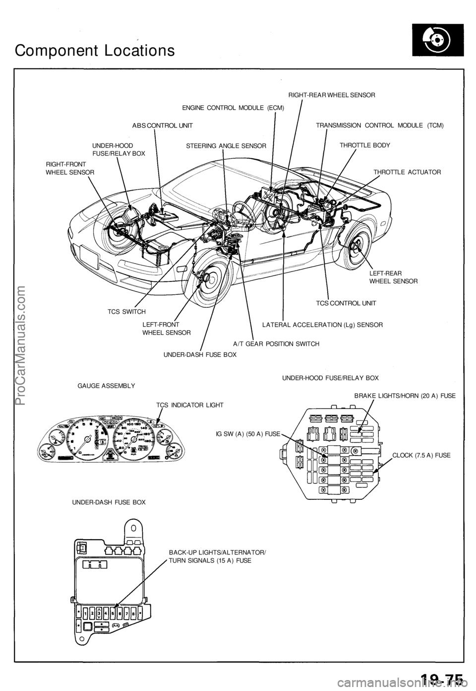
Component Location s
ENGINE CONTRO L MODUL E (ECM )
ABS CONTRO L UNI T
UNDER-HOO D
FUSE/RELA Y BO X
RIGHT-FRON T
WHEE L SENSO R RIGHT-REA
R WHEE L SENSO R
TRANSMISSIO N CONTRO L MODUL E (TCM )
THROTTL E BOD Y
THROTTL E ACTUATO R
LEFT-REARWHEEL SENSO R
TC S SWITC H
LEFT-FRON T
WHEE L SENSO R
TCS CONTRO L UNI T
LATERAL ACCELERATION (Lg) SENSOR
A/T GEA R POSITIO N SWITC H
UNDER-DAS H FUS E BO X
GAUG E ASSEMBL Y UNDER-HOO
D FUSE/RELA Y BO X
BRAK E LIGHTS/HOR N (2 0 A ) FUS E
TC S INDICATO R LIGH T
I G S W (A ) (5 0 A ) FUS E
UNDER-DAS H FUS E BO X CLOC
K (7. 5 A ) FUS E
BACK-U P LIGHTS/ALTERNATOR /
TUR N SIGNAL S (1 5 A ) FUS E
STEERIN
G ANGL E SENSO R
ProCarManuals.com
Page 554 of 1640
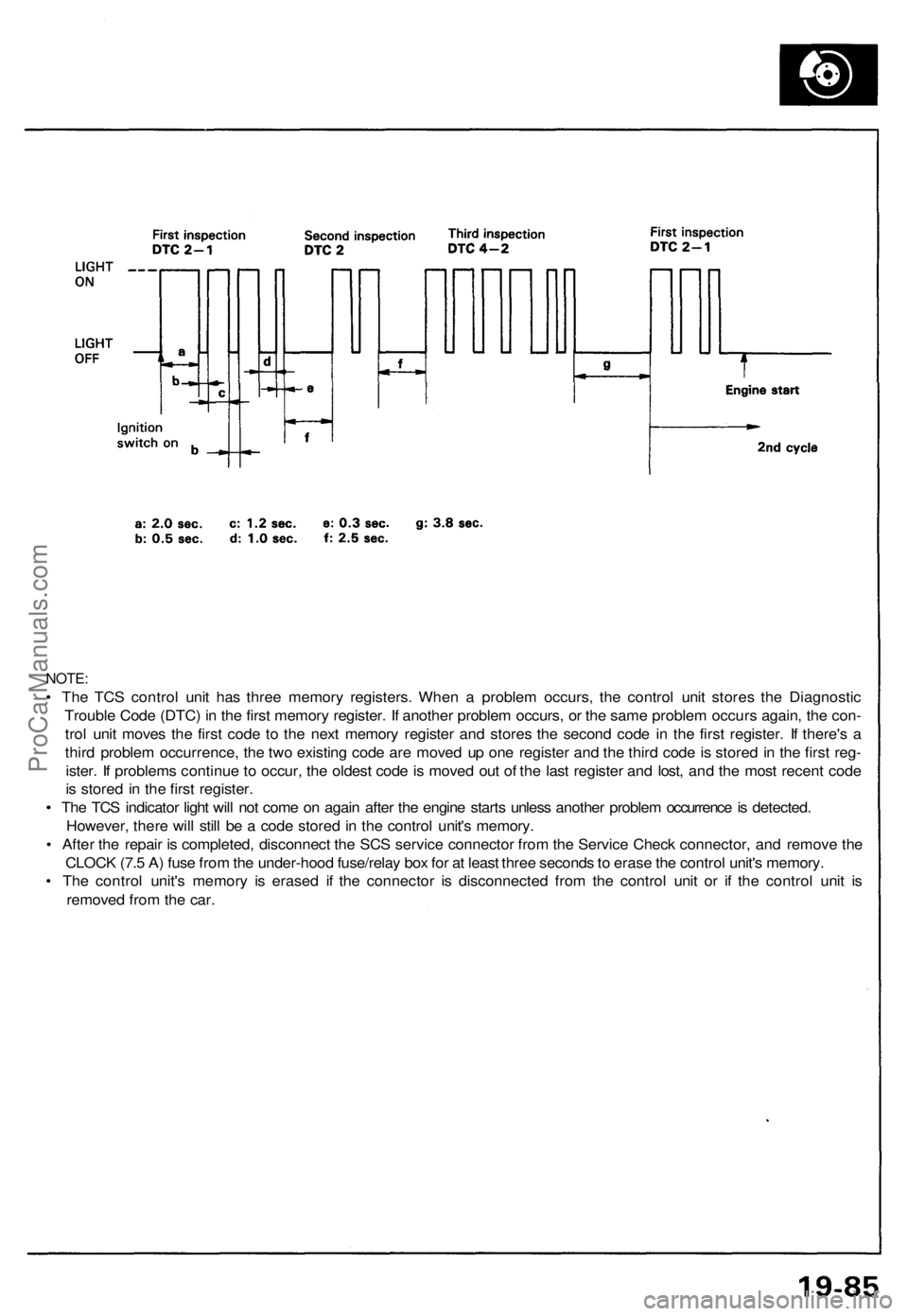
NOTE:
• Th e TC S contro l uni t ha s thre e memor y registers . Whe n a proble m occurs , th e contro l uni t store s th e Diagnosti c
Troubl e Cod e (DTC ) i n th e firs t memor y register . I f anothe r proble m occurs , o r th e sam e proble m occur s again , th e con -
tro l uni t move s th e firs t cod e t o th e nex t memor y registe r an d store s th e secon d cod e i n th e firs t register . I f there' s a
thir d proble m occurrence , th e tw o existin g cod e ar e move d u p on e registe r an d th e thir d cod e is store d in th e firs t reg -
ister . I f problem s continu e t o occur , th e oldes t cod e is move d ou t o f th e las t registe r an d lost , an d th e mos t recen t cod e
i s store d in th e firs t register .
• Th e TC S indicato r ligh t wil l no t com e o n agai n afte r th e engin e start s unles s anothe r proble m occurrenc e is detected .
However , ther e wil l stil l b e a cod e store d in th e contro l unit' s memory .
• Afte r th e repai r i s completed , disconnec t th e SC S servic e connecto r fro m th e Servic e Chec k connector , an d remov e th e
CLOC K (7. 5 A ) fus e fro m th e under-hoo d fuse/rela y bo x fo r a t leas t thre e second s to eras e th e contro l unit' s memory .
• Th e contro l unit' s memor y i s erase d i f th e connecto r i s disconnecte d fro m th e contro l uni t o r i f th e contro l uni t i s
remove d fro m th e car .
ProCarManuals.com
Page 595 of 1640
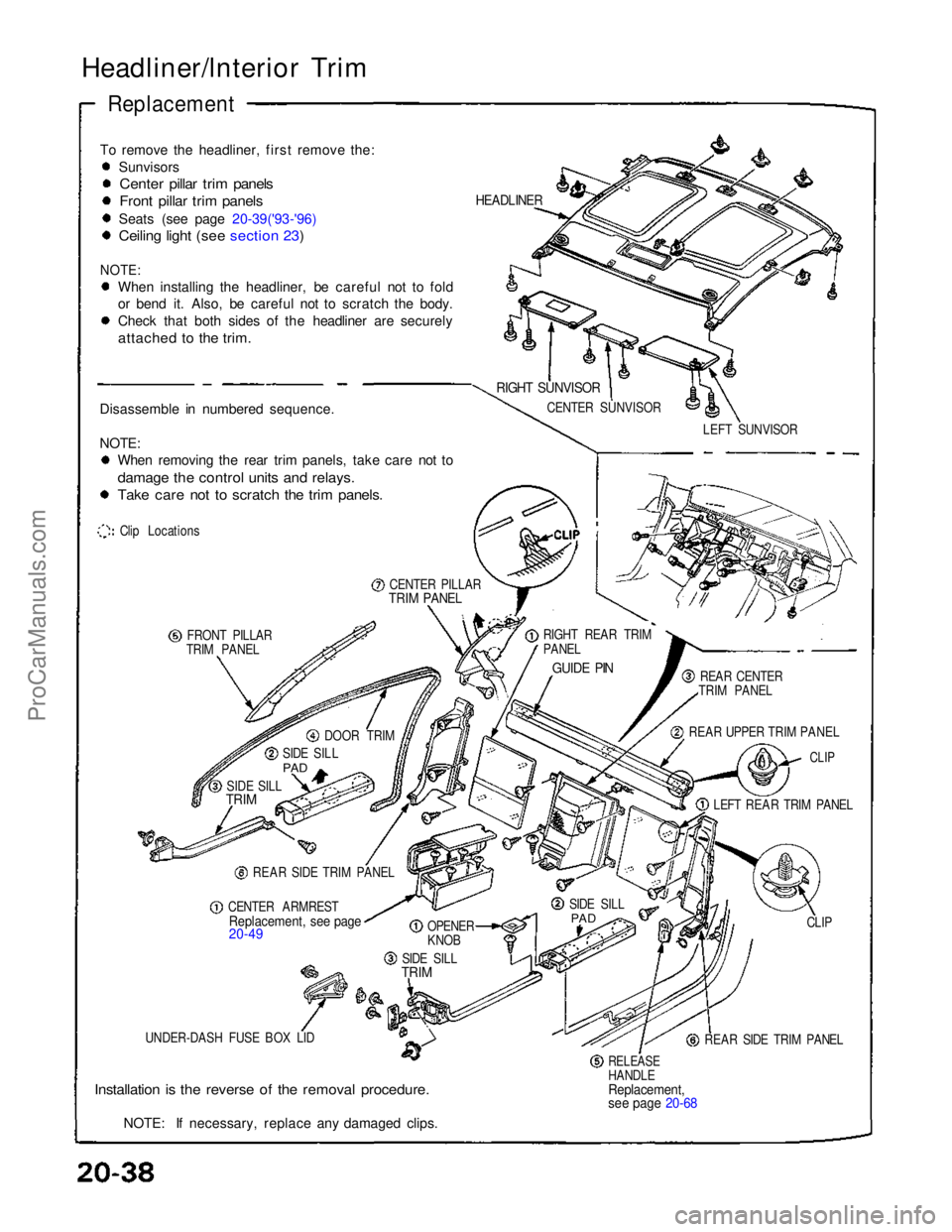
Headliner/lnterior Trim
Replacement
To remove the headliner, first remove the: Sunvisors
Center pillar trim panels
Front pillar trim panels
Seats (see page 20-39('93-'96)
Ceiling light (see section 23)
NOTE:
When installing the headliner, be careful not to fold
or bend it. Also, be careful not to scratch the body.
Check that both sides of the headliner are securely
attached to the trim.
Disassemble in numbered sequence.
NOTE: When removing the rear trim panels, take care not to
damage the control units and relays.
Take care not to scratch the trim panels.
Clip Locations
CENTER PILLAR
TRIM PANEL
FRONT PILLAR
TRIM PANEL
DOOR TRIM
SIDE SILL
PAD
SIDE SILL
TRIM
REAR SIDE TRIM PANEL
CENTER ARMREST
Replacement, see page
20-49
OPENER
KNOB
SIDE SILL
TRIM
UNDER-DASH FUSE BOX LID
Installation is the reverse of the removal procedure.
NOTE: If necessary, replace any damaged clips.
RELEASE
HANDLE
Replacement,
see page 20-68
REAR SIDE TRIM PANEL CLIP
SIDE SILL
PAD
LEFT REAR TRIM PANEL
CLIP
REAR UPPER TRIM PANEL REAR CENTER
TRIM PANEL
GUIDE PIN
RIGHT REAR TRIM
PANEL LEFT SUNVISOR
CENTER SUNVISOR
RIGHT SUNVISOR
HEADLINERProCarManuals.com
Page 604 of 1640
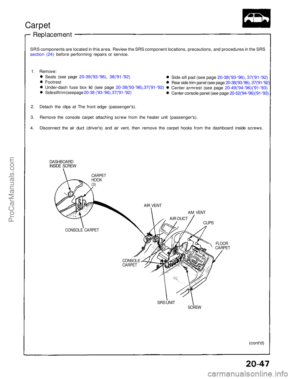
Carpet
Replacement
SRS components are located in this area. Review the SRS component locations, precautions, and procedures in the SRS
section (24) before performing repairs or service.
DASHBOARD
INSIDE SCREW
CARPET
HOOK
(3)
AIR VENT
AM VENT
AIR DUCT
CUPS
FLOOR
CARPET
CONSOLE
CARPET
CONSOLE CARPET
SRS UNIT
SCREW
(cont'd)
1. Remove:
Seats (see page 20-39('93-'96), 38('91-'92)
Footrest
Under-dash fuse box lid (see page 20-38('93-'96),37('91-'92)
Side sill trim (see page 20-38 ('93-'96), 37('91-'92)
Side sill pad (see page 20-38('93-'96), 37('91-'92)
Rear side trim panel (see page 20-38('93-'96), 37('91-'92)
Center armrest (see page 20-49('94-'96)('91-'93)
Center console panel (see page 20-52('94-'96)('91-'93)
2. Detach the clips at The front edge (passenger's).
3. Remove the console carpet attaching screw from the heater unit (passenger's).
4. Disconnect the air duct (driver's) and air vent, then remove the carpet hooks from the dashboard inside screws.ProCarManuals.com
Page 684 of 1640
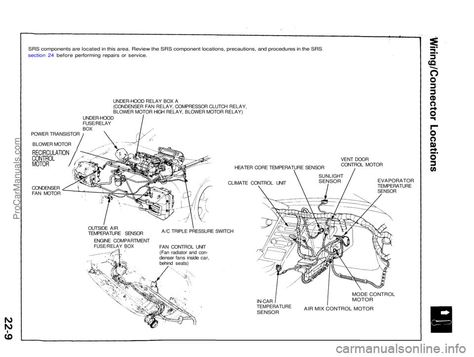
SRS components are located in this area. Review the SRS component locations, precautions, and procedures in the SRS
section 24 before performing repairs or service.
POWER TRANSISTORBLOWER MOTOR
RECIRCULATION
CONTROL
MOTOR
CONDENSER
FAN MOTOR UNDER-HOOD RELAY BOX A
(CONDENSER FAN RELAY, COMPRESSOR CLUTCH RELAY,
BLOWER MOTOR HIGH RELAY, BLOWER MOTOR RELAY)
UNDER-HOOD
FUSE/RELAY
BOX
HEATER CORE TEMPERATURE SENSOR
CLIMATE CONTROL UNIT VENT DOOR
CONTROL MOTOR
OUTSIDE AIR
TEMPERATURE SENSOR ENGINE COMPARTMENT
FUSE/RELAY BOX
A/C TRIPLE PRESSURE SWITCH
FAN CONTROL UNIT (Fan radiator and con-
denser fans inside car,
behind seats)
EVAPORATOR
TEMPERATURE
SENSOR
IN-CAR
TEMPERATURE
SENSOR
MODE CONTROL
MOTOR
AIR MIX CONTROL MOTOR
SUNLIGHT
SENSORProCarManuals.com
Page 729 of 1640
Troubleshooting
Tips and Precautions
Before Troubleshooting
• Check applicable fuses in the appropriate fuse box.
• Check the battery for damage, state of charge, and
clean and tight connections.
• Check the alternator belt tension.
CAUTION:
• Do not quick-charge a battery unless the battery
ground cable has been disconnected.
Otherwise you will damage the alternator
diodes.
• Do not attempt to crank the engine with the bat-
tery ground cable loosely connected or you will
severely damage the wiring.
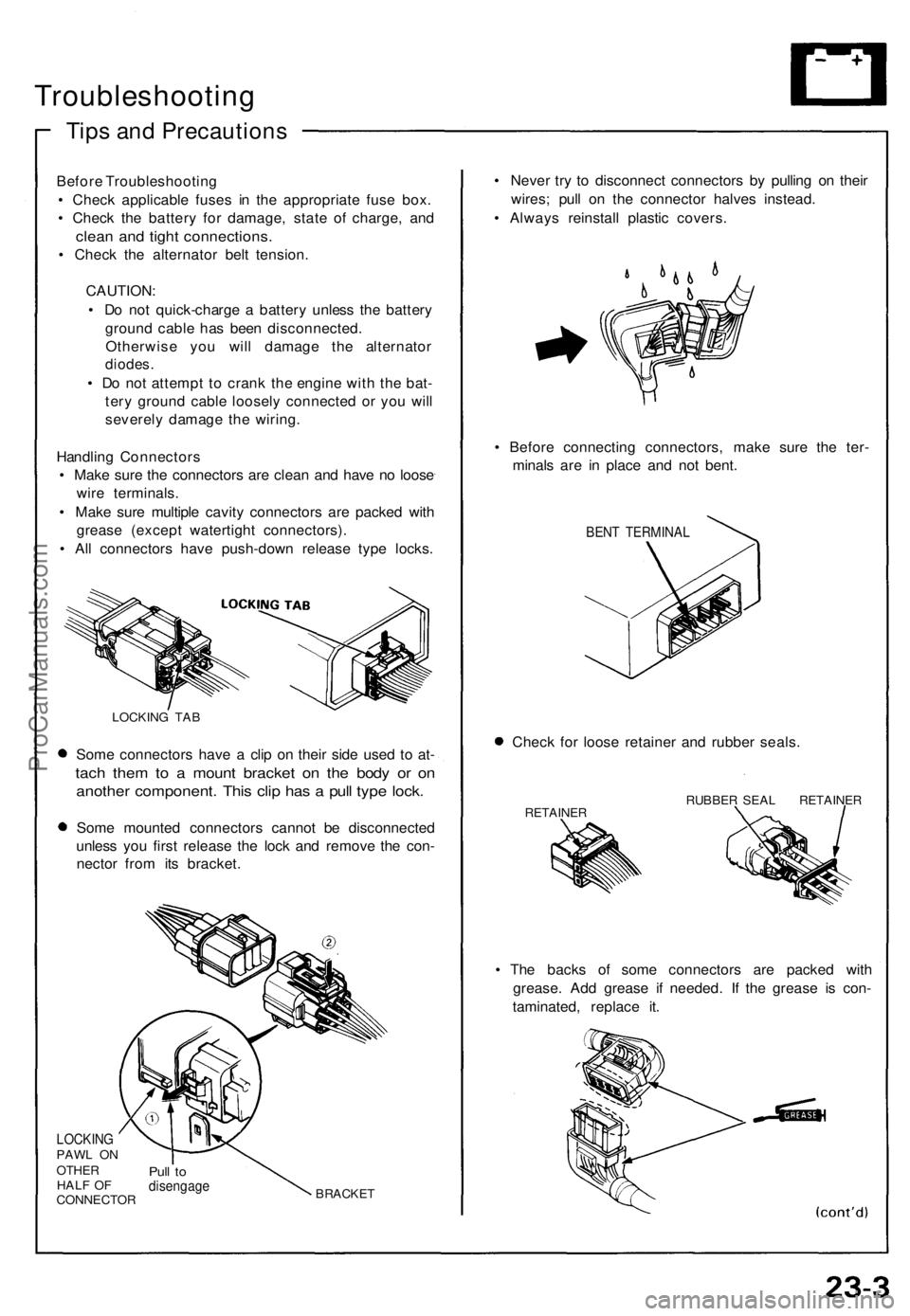
Handling Connectors
• Make sure the connectors are clean and have no loose
wire terminals.
• Make sure multiple cavity connectors are packed with
grease (except watertight connectors).
• All connectors have push-down release type locks.
LOCKING TAB
Some connectors have a clip on their side used to at-
tach them to a mount bracket on the body or on
another component. This clip has a pull type lock.
Some mounted connectors cannot be disconnected
unless you first release the lock and remove the con-
nector from its bracket.
LOCKING
PAWL ON
OTHER
HALF OF
CONNECTOR
Pull to
disengage
BRACKET
• Never try to disconnect connectors by pulling on their
wires; pull on the connector halves instead.
• Always reinstall plastic covers.
• Before connecting connectors, make sure the ter-
minals are in place and not bent.
BENT TERMINAL
Check for loose retainer and rubber seals.
RETAINER
RUBBER SEAL RETAINER
• The backs of some connectors are packed with
grease. Add grease if needed. If the grease is con-
taminated, replace it.ProCarManuals.com
Page 731 of 1640

Five-step Troubleshooting
1. Verify The Complaint
Turn on all the components in the problem circuit to
verify the customer complaint. Note the symp-
toms. Do not begin disassembly or testing until you
have narrowed down the problem area.
2. Analyze The Schematic
Look up the schematic for the problem circuit.
Determine how the circuit is supposed to work by
tracing the current paths from the power feed
through the circuit components to ground. If
several circuits fail at the same time, the fuse or
ground is a likely cause.
Based on the symptoms and your understanding of
the circuit operation, identify one or more possible
causes of the problem.
3. Isolate The Problem By Testing The Circuit
Make circuit tests to check the diagnosis you made
in step 2. Keep in mind that a logical, simple pro-
cedure is the key to efficient troubleshooting. Test
for the most likely cause of failure first. Try to make
tests at points that are easily accessible.
4. Fix The Problem
Once the specific problem is identified, make the
repair. Be sure to use proper tools and safe
procedures.
5. Make Sure The Circuit Works
Turn on all components in the repaired circuit in all
modes to make sure you've fixed the entire pro-
blem. If the problem was a blown fuse, be sure to
test all of the circuits on that fuse. Make sure no
new problems turn up and the original problem
does not recur.ProCarManuals.com
Page 732 of 1640
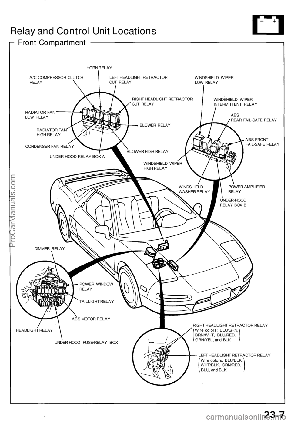
Relay and Control Unit Locations
Front Compartment
HORN RELAY
A/C COMPRESSOR CLUTCH
RELAY
RADIATOR FAN
LOW RELAY
RADIATOR FAN
HIGH RELAY
CONDENSER FAN RELAY
UNDER-HOOD RELAY BOX A
LEFT HEADLIGHT RETRACTOR
CUT RELAY
WINDSHIELD WIPER
LOW RELAY
WINDSHIELD WIPER
INTERMITTENT RELAY
POWER AMPLIFIER
RELAY
ABS
REAR FAIL-SAFE RELAY
ABS FRONT
FAIL-SAFE RELAY
HEADLIGHT RELAY
RIGHT HEADLIGHT RETRACTOR RELAY
Wire colors: BLU/GRN,
BRN/WHT, BLU/RED,
GRN/YEL, and BLK
LEFT HEADLIGHT RETRACTOR RELAY
Wire colors: BLU/BLK,
WHT/BLK, GRN/RED,
BLU,
and BLK
RIGHT HEADLIGHT RETRACTOR
CUT RELAY
BLOWER RELAY
BLOWER HIGH RELAY
WINDSHIELD WIPER
HIGH RELAY
WINDSHIELD
WASHER RELAY
UNDER-HOOD
RELAY BOX B
DIMMER RELAY
POWER WINDOW
RELAY
TAILLIGHT RELAY
ABS MOTOR RELAY
UNDER-HOOD FUSE/RELAY BOXProCarManuals.com
Page 733 of 1640
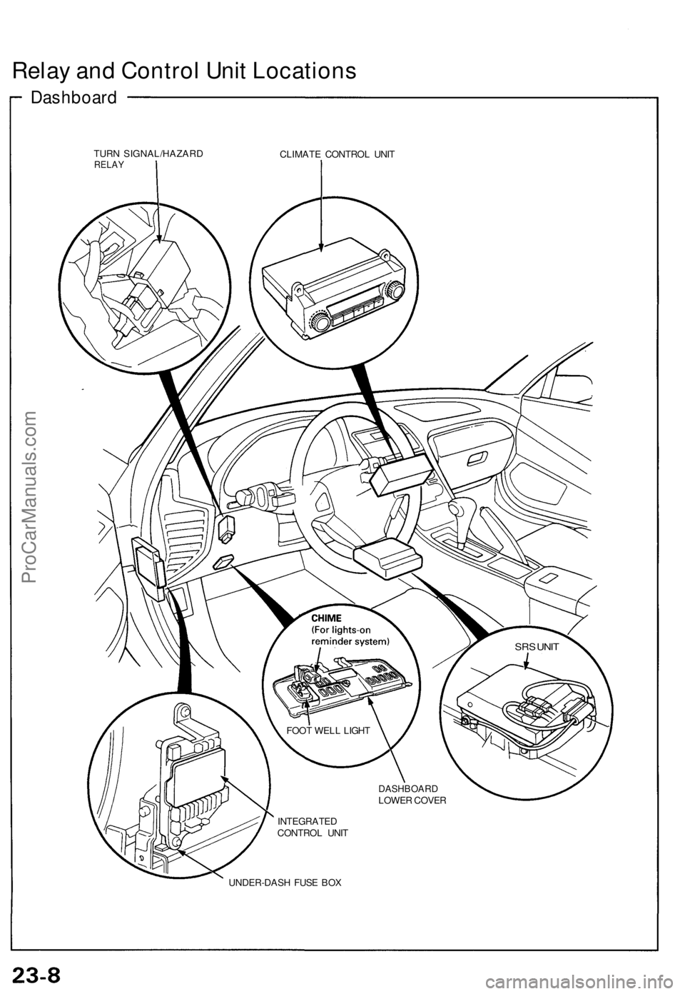
Relay and Control Unit Locations
Dashboard
TURN SIGNAL/HAZARD
RELAY
CLIMATE CONTROL UNIT
UNDER-DASH FUSE BOX
FOOT WELL LIGHT
DASHBOARD
LOWER COVER
INTEGRATED
CONTROL UNIT
SRS UNITProCarManuals.com
Page 737 of 1640
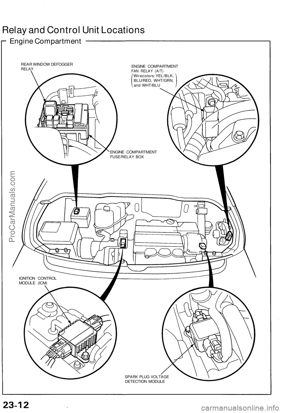
Relay and Control Unit Locations
Engine Compartment
REAR WINDOW DEFOGGER
RELAY
ENGINE COMPARTMENT
FAN RELAY (A/T)
Wire colors: YEL/BLK,
BLU/RED, WHT/GRN,
and WHT/BLU
SPARK PLUG VOLTAGE
DETECTION MODULE
ENGINE COMPARTMENT
FUSE/RELAY BOX
IGNITION CONTROL
MODULE (ICM)ProCarManuals.com