clock setting ACURA NSX 1991 Service Repair Manual
[x] Cancel search | Manufacturer: ACURA, Model Year: 1991, Model line: NSX, Model: ACURA NSX 1991Pages: 1640, PDF Size: 60.48 MB
Page 1079 of 1640

II. ENGINE CONTROL MODULE (ECM) Reset Procedure
1. Turn the ignition switch off.
2. Remove the CLOCK (7.5 A) fuse from the under-hood fuse/relay box for 10 seconds to reset ECM.
NOTE: Disconnecting the CLOCK fuse also cancels the radio preset stations and the clock setting. Make note of
the radio presets before removing the fuse so you can reset them.
III. Final Procedure (this procedure must be done after any troubleshooting)
1. Remove the Jumper Wire.
NOTE: If the Service Check Connector is jumped, the MIL will stay on.
2. Do the ECM Reset Procedure.
3. Set the radio preset stations and the clock setting.
(cont'd)
CLOCK
(7.5 A) FUSE
UNDER-HOOD
FUSE/RELAY BOXProCarManuals.com
Page 1106 of 1640
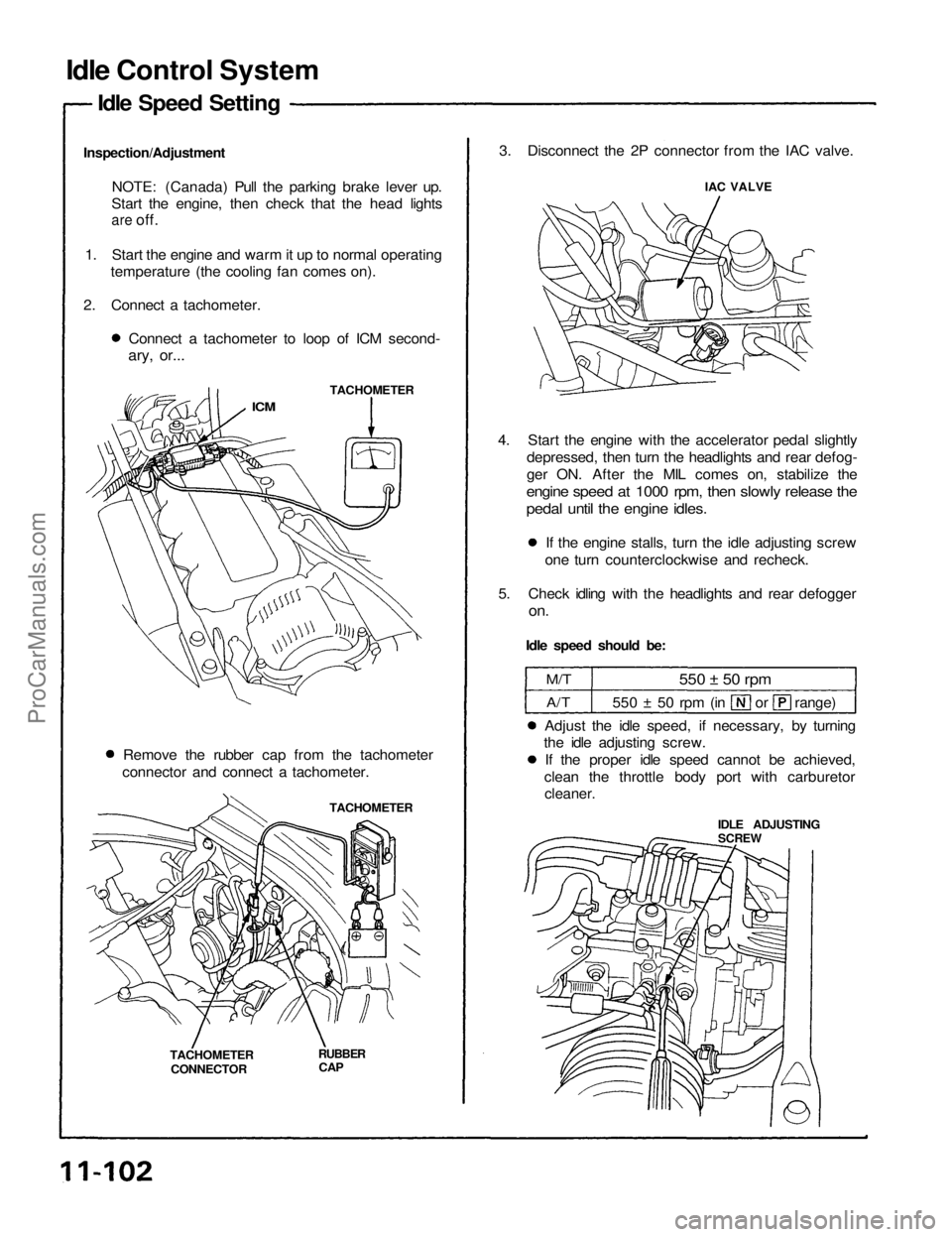
Idle Control System
Idle Speed Setting
Inspection/Adjustment NOTE: (Canada) Pull the parking brake lever up.
Start the engine, then check that the head lights
are
off.
1. Start the engine and warm it up to normal operating temperature (the cooling fan comes on).
2. Connect a tachometer. Connect a tachometer to loop of ICM second-
ary, or...
TACHOMETER
ICM
Remove the rubber cap from the tachometer
connector and connect a tachometer.
TACHOMETER
TACHOMETER CONNECTOR
RUBBER
CAP
3. Disconnect the 2P connector from the IAC valve.
IAC VALVE
4. Start the engine with the accelerator pedal slightly depressed, then turn the headlights and rear defog-
ger ON. After the MIL comes on, stabilize the
engine speed at 1000 rpm, then slowly release the
pedal until the engine idles.
If the engine stalls, turn the idle adjusting screw
one turn counterclockwise and recheck.
5. Check idling with the headlights and rear defogger
on.
Idle speed should be:
M/T
A/T
550 ± 50 rpm
550 ± 50 rpm (in or range)
Adjust the idle speed, if necessary, by turning
the idle adjusting screw.
If the proper idle speed cannot be achieved,
clean the throttle body port with carburetor
cleaner.
IDLE ADJUSTING
SCREWProCarManuals.com
Page 1208 of 1640
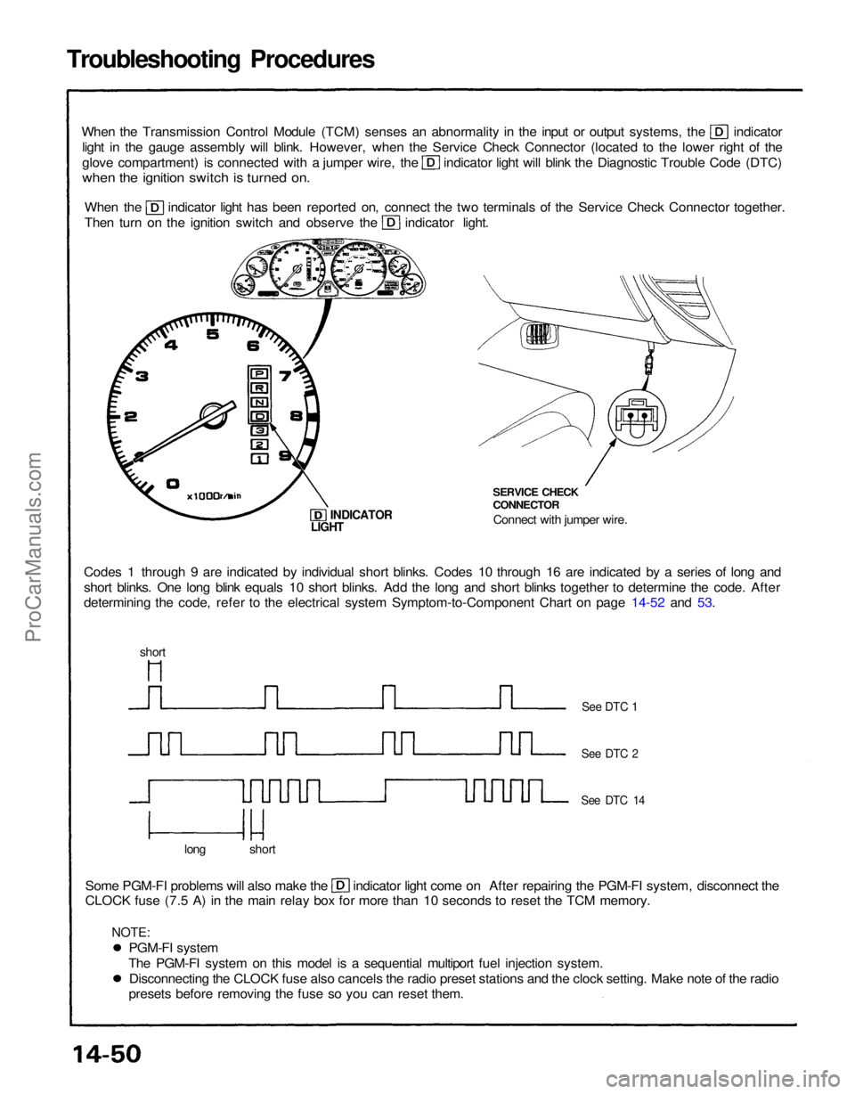
Troubleshooting Procedures
When the Transmission Control Module (TCM) senses an abnormality in the input or output systems, the indicator
light in the gauge assembly will blink. However, when the Service Check Connector (located to the lower right of the glove compartment) is connected with a jumper wire, the indicator light will blink the Diagnostic Trouble Code (DTC)
when the ignition switch is turned on.
When the indicator light has been reported on, connect the two terminals of the Service Check Connector together.
Then turn on the ignition switch and observe the indicator light.
Codes 1 through 9 are indicated by individual short blinks. Codes 10 through 16 are indicated by a series of long and
short blinks. One long blink equals 10 short blinks. Add the long and short blinks together to determine the code. After
determining the code, refer to the electrical system Symptom-to-Component Chart on page 14-52 and 53. SERVICE CHECK
CONNECTOR
Connect with jumper wire.
INDICATOR
Some PGM-FI problems will also make the indicator light come on After repairing the PGM-FI system, disconnect the
CLOCK fuse (7.5 A) in the main relay box for more than 10 seconds to reset the TCM memory.
long short
See DTC 1
See DTC 2
See DTC 14
LIGHT
short
PGM-FI system
The PGM-FI system on this model is a sequential multiport fuel injection system. Disconnecting the CLOCK fuse also cancels the radio preset stations and the clock setting. Make note of the radio
presets before removing the fuse so you can reset them.
NOTE:ProCarManuals.com
Page 1209 of 1640
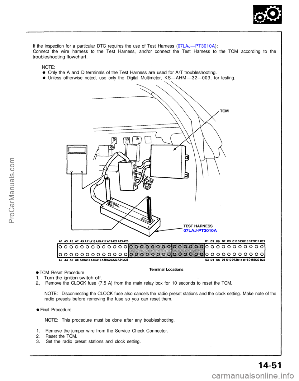
If the inspection for a particular DTC requires the use of Test Harness (07LAJ—PT3010A):
Connect the wire harness to the Test Harness, and/or connect the Test Harness to the TCM according to the
troubleshooting flowchart.
TCM
TEST HARNESS
Terminal Locations
TCM Reset Procedure
Turn the ignition switch off. -
, Remove the CLOCK fuse (7.5 A) from the main relay box for 10 seconds to reset the TCM.
1
2
NOTE: Disconnecting the CLOCK fuse also cancels the radio preset stations and the clock setting. Make note of the
radio presets before removing the fuse so you can reset them.
Final Procedure NOTE: This procedure must be done after any troubleshooting.
1. Remove the jumper wire from the Service Check Connector.
2. Reset the TCM. 3. Set the radio preset stations and clock setting.
Only the A and D terminals of the Test Harness are used for A/T troubleshooting.
Unless otherwise noted, use only the Digital Multimeter, KS—AHM —32—003, for testing.
07LAJ-PT3010A
NOTE:ProCarManuals.com
Page 1211 of 1640
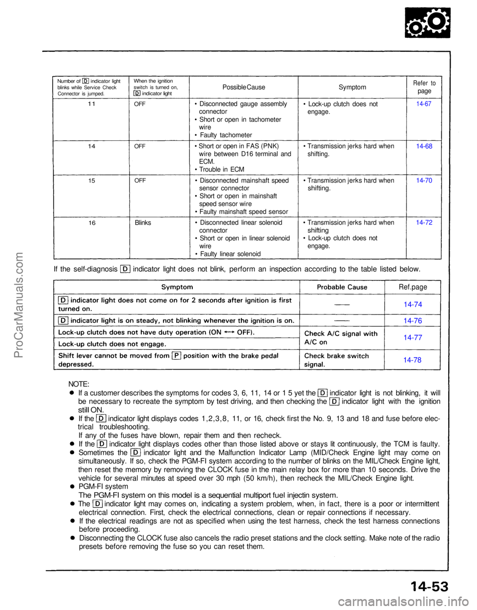
If a customer describes the symptoms for codes 3, 6, 11, 14 or 1 5 yet the indicator light is not blinking, it will
be necessary to recreate the symptom by test driving, and then checking the indicator light with the ignition
still
ON.
If the indicator light displays codes 1,2,3,8, 11, or 16, check first the No. 9, 13 and 18 and fuse before elec-
trical troubleshooting.
If any of the fuses have blown, repair them and then recheck. If the indicator light displays codes other than those listed above or stays lit continuously, the TCM is faulty.
Sometimes the indicator light and the Malfunction Indicator Lamp (MID/Check Engine light may come on
simultaneously. If so, check the PGM-FI system according to the number of blinks on the MIL/Check Engine light,
then reset the memory by removing the CLOCK fuse in the main relay box for more than 10 seconds. Drive the vehicle for several minutes at speed over 30 mph (50 km/h), then recheck the MIL/Check Engine light.PGM-FI system
The PGM-FI system on this model is a sequential multiport fuel injectin system.
The indicator light may comes on, indicating a system problem, when, in fact, there is a poor or intermittent
electrical connection. First, check the electrical connections, clean or repair connections if necessary.If the electrical readings are not as specified when using the test harness, check the test harness connections
before proceeding.
Disconnecting the CLOCK fuse also cancels the radio preset stations and the clock setting. Make note of the radio
presets before removing the fuse so you can reset them. If the self-diagnosis indicator light does not blink, perform an inspection according to the table listed below.
Symptom
• Lock-up clutch does not
engage.
• Transmission jerks hard when shifting.
• Transmission jerks hard when
shifting.
• Transmission jerks hard when
shifting
• Lock-up clutch does not
engage.
14-7214-70 14-68
14-67
Refer to
page
Possible Cause
• Disconnected gauge assembly connector
• Short or open in tachometer wire
• Faulty tachometer
• Short or open in FAS (PNK) wire between D16 terminal and
ECM.
• Trouble in ECM
• Disconnected mainshaft speed sensor connector
• Short or open in mainshaft speed sensor wire
• Faulty mainshaft speed sensor
• Disconnected linear solenoid connector
• Short or open in linear solenoid wire
• Faulty linear solenoid
Blinks
OFF
OFF
OFF
When the ignition
switch is turned on,
indicator light
Number of indicator light
blinks while Service CheckConnector is jumped.
11
14
15
16
Ref.page
14-74
14-76
14-77
14-78
NOTE:ProCarManuals.com
Page 1375 of 1640
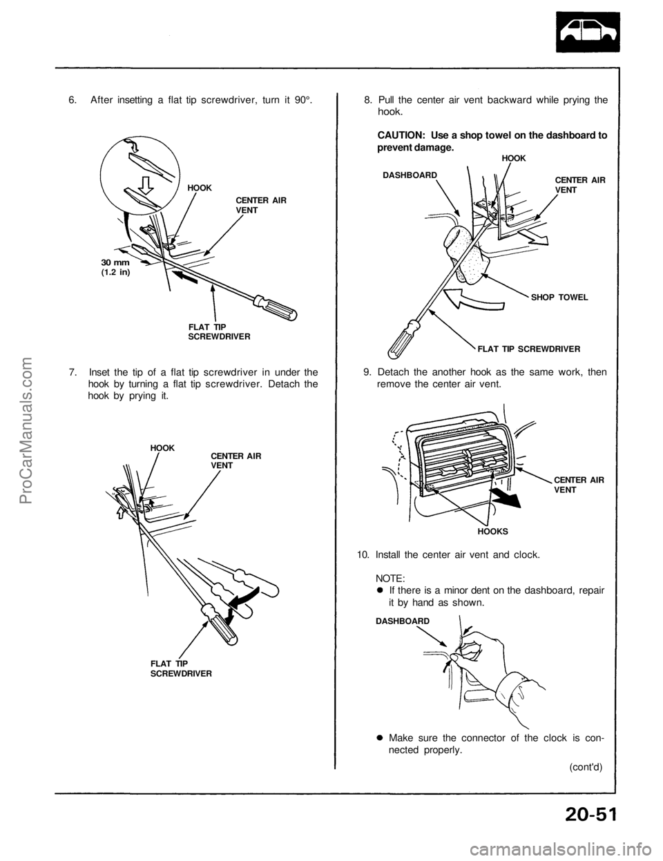
6. After insetting a flat tip screwdriver, turn it 90°.
HOOK
CENTER AIR
VENT
30 mm
(1.2
in)
FLAT TIP
SCREWDRIVER
7. Inset the tip of a flat tip screwdriver in under the
hook by turning a flat tip screwdriver. Detach the
hook by prying it.
HOOK
CENTER AIR
VENT
FLAT TIP
SCREWDRIVER
8. Pull the center air vent backward while prying the
hook.
CAUTION: Use a shop towel on the dashboard to
prevent damage.
DASHBOARD
HOOK
CENTER AIR
VENT
SHOP TOWEL
FLAT TIP SCREWDRIVER
9. Detach the another hook as the same work, then
remove the center air vent.
CENTER AIR
VENT
HOOKS
10. Install the center air vent and clock.
NOTE:
DASHBOARD
Make sure the connector of the clock is con-
nected properly.
(cont'd)
If there is a minor dent on the dashboard, repair
it by hand as shown.ProCarManuals.com
Page 1393 of 1640
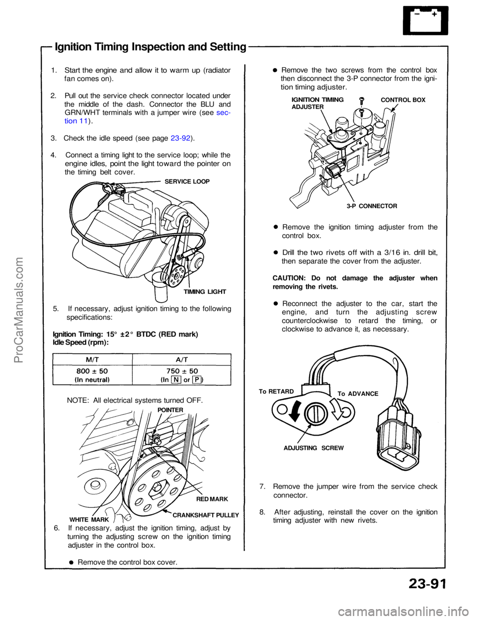
Ignition Timing Inspection and Setting
1. Start the engine and allow it to warm up (radiator
fan comes on).
2. Pull out the service check connector located under the middle of the dash. Connector the BLU andGRN/WHT terminals with a jumper wire (see sec-
tion 11).
3. Check the idle speed (see page 23-92).
4. Connect a timing light to the service loop; while the
engine idles, point the light toward the pointer on
the timing belt cover.
SERVICE LOOP
TIMING LIGHT
5. If necessary, adjust ignition timing to the following specifications:
Ignition Timing: 15° ±2° BTDC (RED mark)
Idle Speed (rpm):
NOTE: All electrical systems turned OFF. POINTER
RED MARK
CRANKSHAFT PULLEY
WHITE MARK
6. If necessary, adjust the ignition timing, adjust by turning the adjusting screw on the ignition timingadjuster in the control box.
Remove the control box cover. 7. Remove the jumper wire from the service check
connector.
8. After adjusting, reinstall the cover on the ignition timing adjuster with new rivets.ADJUSTING SCREW
To ADVANCE
To RETARD Reconnect the adjuster to the car, start the
engine, and turn the adjusting screw
counterclockwise to retard the timing, or
clockwise to advance it, as necessary.
CAUTION: Do not damage the adjuster when
removing the rivets. Remove the ignition timing adjuster from the
control box.
Drill the two rivets off with a 3/16 in. drill bit,
then separate the cover from the adjuster. 3-P CONNECTORCONTROL BOX
IGNITION TIMING
ADJUSTER
Remove the two screws from the control box
then disconnect the 3-P connector from the igni-
tion timing adjuster.ProCarManuals.com
Page 1498 of 1640
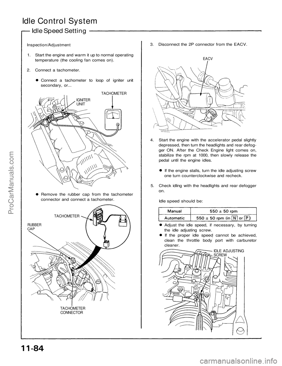
Idle Control System
Idle Speed Setting
Inspection/Adjustment
1. Start the engine and warm it up to normal operating temperature (the cooling fan comes on).
2. Connect a tachometer. Connect a tachometer to loop of igniter unit
secondary, or... 3. Disconnect the 2P connector from the EACV.
EACV
TACHOMETER
IGNITER
UNIT
4. Start the engine with the accelerator pedal slightlydepressed, then turn the headlights and rear defog-
ger ON. After the Check Engine light comes on,stabilize the rpm at 1000, then slowly release the
pedal until the engine idles. If the engine stalls, turn the idle adjusting screw
one turn counterclockwise and recheck.
5. Check idling with the headlights and rear defogger
on.
Idle speed should be:
Remove the rubber cap from the tachometer
connector and connect a tachometer.
TACHOMETER
RUBBER
CAP
Adjust the idle speed, if necessary, by turning
the idle adjusting screw. If the proper idle speed cannot be achieved,
clean the throttle body port with carburetor
cleaner.
IDLE ADJUSTING
SCREW
TACHOMETER CONNECTORProCarManuals.com