engine coolant ACURA NSX 1991 Service Repair Manual
[x] Cancel search | Manufacturer: ACURA, Model Year: 1991, Model line: NSX, Model: ACURA NSX 1991Pages: 1640, PDF Size: 60.48 MB
Page 72 of 1640
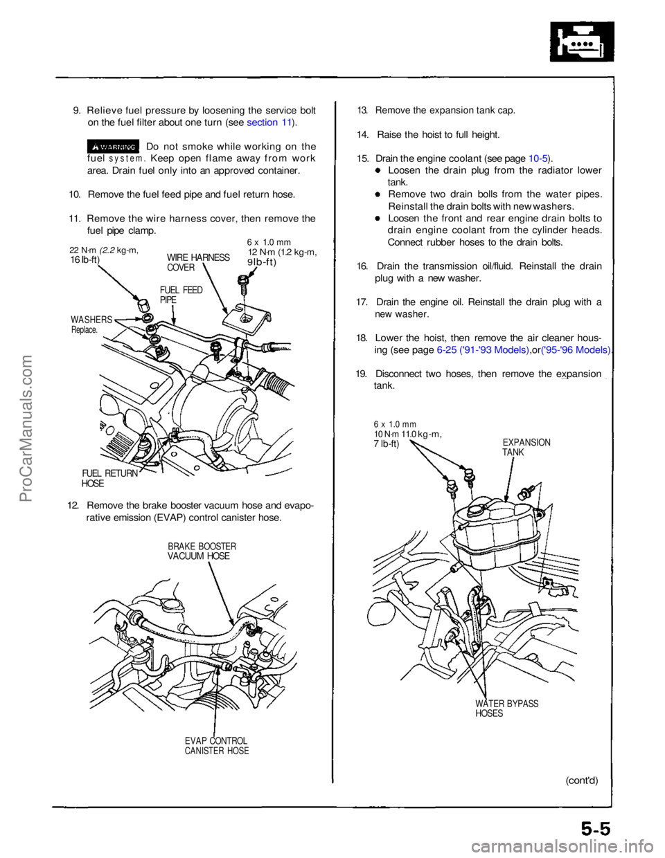
9. Relieve fuel pressure by loosening the service bolt
on the fuel filter about one turn (see section 11).
Do not smoke while working on the
fuel
system.
Keep open flame away from work
area. Drain fuel only into an approved container.
10. Remove the fuel feed pipe and fuel return hose.
11. Remove the wire harness cover, then remove the fuel pipe clamp.
22 N·m
(2.2 kg-m,
16 Ib-ft)
WIRE HARNESS
COVER
6 x 1.0 mm
12 N·m
(1.2 kg-m,
9 lb-ft)
FUEL FEED
PIPE
WASHERS
Replace.
FUEL RETURN
HOSE
12. Remove the brake booster vacuum hose and evapo- rative emission (EVAP) control canister hose.
BRAKE BOOSTER
VACUUM HOSE
EVAP CONTROL
CANISTER HOSE
13. Remove the expansion tank cap.
14. Raise the hoist to full height.
15. Drain the engine coolant (see page
10-5).
Loosen the drain plug from the radiator lower
tank. Remove two drain bolls from the water pipes.
Reinstall the drain bolts with new washers.
Loosen the front and rear engine drain bolts to
drain engine coolant from the cylinder heads.
Connect rubber hoses to the drain bolts.
16. Drain the transmission oil/fluid. Reinstall the drain plug with a new washer.
17. Drain the engine oil. Reinstall the drain plug with a
new washer.
18. Lower the hoist, then remove the air cleaner hous-
ing (see page 6-25 ('91-'93 Mode ls),or('95-'96 Models).
19. Disconnect two hoses, then remove the expansion
tank.
6 x 1.0 mm
10 N·m
11.0 kg-m,
7 lb-ft)
EXPANSION
TANK
WATER BYPASS
HOSES
(cont'd)ProCarManuals.com
Page 89 of 1640
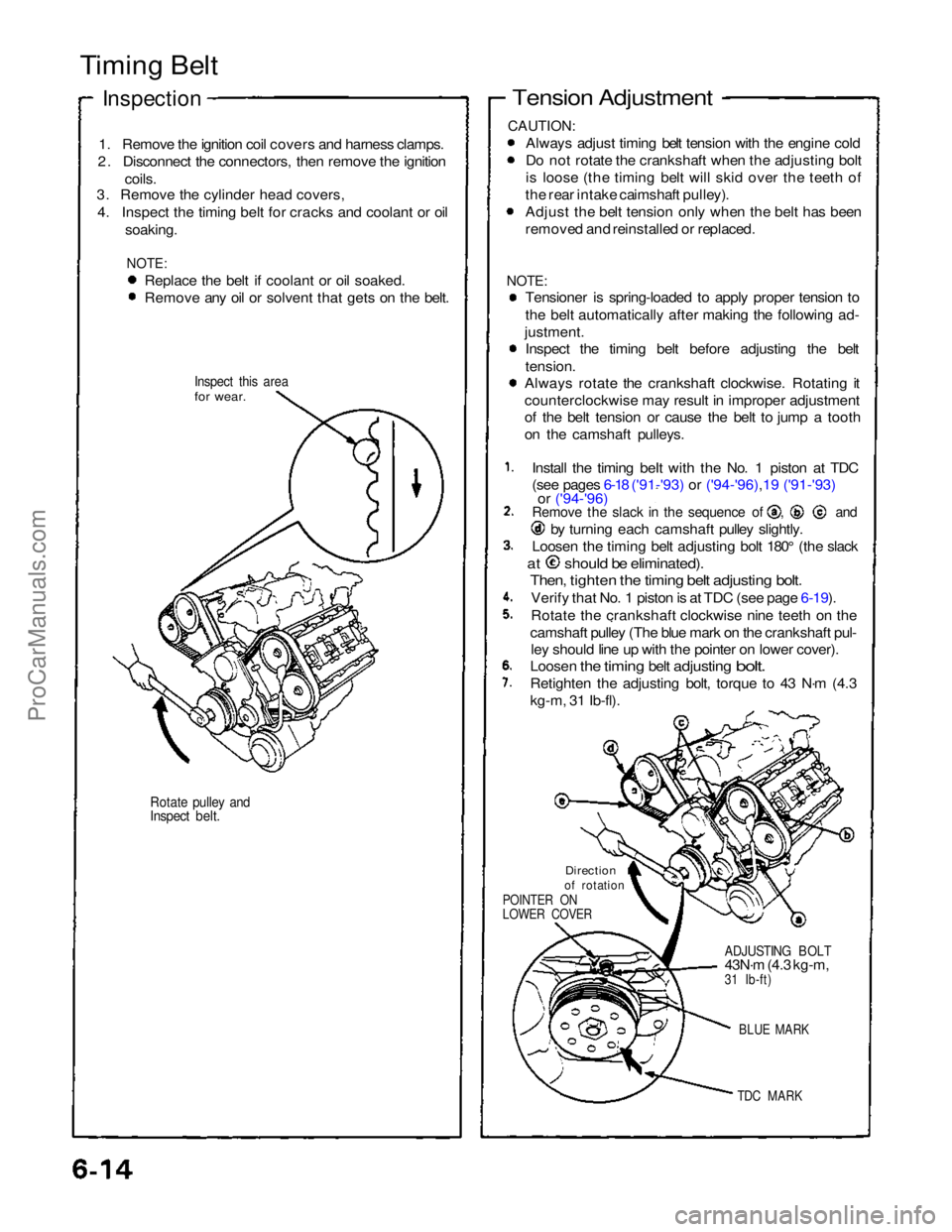
Timing Belt
Inspection
1. Remove the ignition coil covers and harness clamps.
2. Disconnect the connectors, then remove the ignition
coils.
3. Remove the cylinder head covers,
4. Inspect the timing belt for cracks and coolant or oil soaking.
NOTE:
Replace the belt if coolant or oil soaked.
Remove any oil or solvent that gets on the belt.
Inspect this area
for wear.
Rotate pulley and
Inspect belt.
Tension Adjustment
CAUTION:
Always adjust timing belt tension with the engine cold
Do not rotate the crankshaft when the adjusting bolt
is loose (the timing belt will skid over the teeth of
the rear intake caimshaft pulley).
Adjust the belt tension only when the belt has been
removed and reinstalled or replaced.
NOTE:
Tensioner is spring-loaded to apply proper tension to
the belt automatically after making the following ad-
justment. Inspect the timing belt before adjusting the belt
tension.
Always rotate the crankshaft clockwise. Rotating it
counterclockwise may result in improper adjustment
of the belt tension or cause the belt to jump a tooth
on the camshaft pulleys.
Install the timing beIt with the No. 1 piston at TDC
(see pages 6-18 ('91-'93) or ('94-'96),19 ('91-'93)
or ('94-'96) Remove the slack in the sequence of , and
by turning each camshaft pulley slightly.
Loosen the timing belt adjusting bolt 180° (the slack
at should be eliminated).
Then, tighten the timing belt adjusting bolt.
Verify that No. 1 piston is at TDC (see page 6-19).
Rotate the crankshaft clockwise nine teeth on the
camshaft pulley (The blue mark on the crankshaft pul- ley should line up with the pointer on lower cover).
Loosen
the
timing
belt
adjusting
bolt.
Retighten the adjusting bolt, torque to 43 N·m (4.3
kg-m, 31 Ib-fl).
Direction
of rotation
POINTER ON
LOWER COVER
ADJUSTING BOLT
43N·m (4.3 kg-m,
31 Ib-ft)
BLUE MARK
TDC MARK
ProCarManuals.com
Page 97 of 1640
![ACURA NSX 1991 Service Repair Manual
Cylinder Heads
Illustrated Index (cont'd)
CAUTION:
To
avoid
damage,
wait
until
the
engine
coolant
temperature
drops
below
100°F
(39-C]
before
removing
the
cylin-
der head.
N ACURA NSX 1991 Service Repair Manual
Cylinder Heads
Illustrated Index (cont'd)
CAUTION:
To
avoid
damage,
wait
until
the
engine
coolant
temperature
drops
below
100°F
(39-C]
before
removing
the
cylin-
der head.
N](/img/32/56988/w960_56988-96.png)
Cylinder Heads
Illustrated Index (cont'd)
CAUTION:
To
avoid
damage,
wait
until
the
engine
coolant
temperature
drops
below
100°F
(39-C]
before
removing
the
cylin-
der head.
NOTE: Use new O-rings and gaskets when reassembling.
Prior to reassembling, clean all the parts in solvent, dry them, and apply lubricant to any contact parts.
REAR VARIABLE VALVE TIMING
AND VALVE LIFT ELECTRONIC CONTROL
SYSTEM (VTEC) SOLENOID VALVE
Troubleshooting, page 6-3 ('91-'93) or ('94-'96)
EXHAUST GAS
RECIRCULATI0N (EGR) VALVE
6 x 1 .0 mm
12 N·m
(1.2 kg-m.
9 Ib-ft)
8 x
1.25
mm
22 N·m
(2.2 kg-m,
16 Ib-ft)
ENGINE COOLANT
TEMPERATURE (ECT) SENSOR
18 N·m (1.8 kg-m, 13 Ib-ft)
8 x
1.25
mm
22 N·m (2.2 kg-m. 16 lb-ft)
FRONT VTEC SOLENOID VALVE
Troubleshooting. page 6-3
SEALING BOLTS
60 N·m
(6.0 kg-m,
43 lb-ft)
OIL PRESSURE
GAUSE SENDING
UNIT (section 23)
ROCKER
SHAFTS
WASHERS
Replace.
8 x
1.25
mm
22 N·m
(2.2 kg-m,16 Ib-ft)
DOWEL PIN
0-RING
Replace.
ECT SWITCH
28 N·m
12.8 kg-m.
20 lb-ft
O-RING
Replace.
O-RING
Replace.
ROCKER ARM ASSEMBLY[PRIMARY. MID, SECONDARY]
Inspection, page 6-32 ('91-'93) or ('94-'96)
ROCKER SHAFT
OIL CONTROL
ORIFICE
Remove with 5 mm
boit and clean.
FILTER
Replace.
GASKET
Replace.
O-RING
Replace.ProCarManuals.com
Page 99 of 1640
Cylinder Heads
Removal
Engine removal is not required for this procedure. Make sure jacks and safety stands are
placed properly and hoist brackets ere attached to cor- rect positions on the engine.
CAUTION: Use a fender cover (special tool) to avoid damaging
painted surfaces. Unplug the wiring connectors carefully while holding
the connector portion to avoid damage.
To avoid damaging the cylinder heads, wait until the
engine coolant temperature drops below 100°F
(38°C) before loosening the retaining bolts. Do not open the engine cover when the roof panel is
stored (NSX-T open top).
NOTE:
Unspecified items are common.
Mark all wiring and hoses to avoid misconnection.
Also, be sure that they do not contact other wiring or
hoses or interfere with other parts.
Inspect the timing belt before removing the cylinder
head.
Turn the crankshaft pulley SO that the No. 1 piston is at top dead center (see page 6-19 ('91-'93) or ('94-'96)).
1. Disconnect the negative terminal from the battery.
2. Remove the expansion tank cap. Use care when removing the expan-
sion tank cap to avoid scalding by engine coolant
or steam.
3. Raise the car, then remove the right rear wheel/tire.
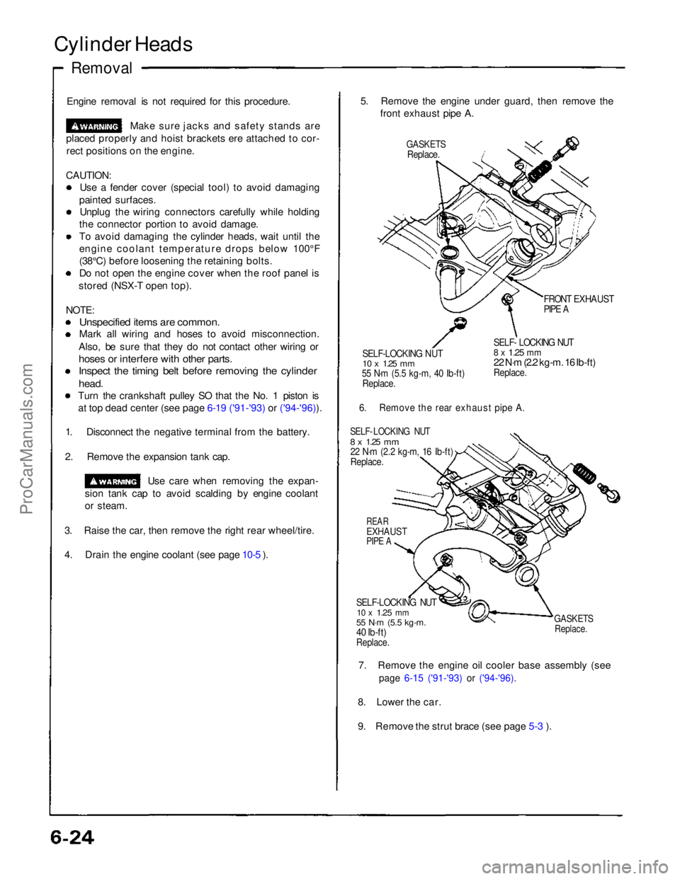
4. Drain the engine coolant (see page 10-5 ). 5. Remove the engine under guard, then remove the
front exhaust pipe A.
GASKETS
Replace.
FRONT EXHAUST
PIPE A
SELF-LOCKING NUT
10 x
1.25
mm
55 N·m (5.5 kg-m, 40 Ib-ft)
Replace.
SELF- LOCKING NUT
8 x
1.25
mm
22 N·m (2.2 kg-m. 16 Ib-ft)
Replace.
6. Remove the rear exhaust pipe A.
SELF- LOCKING NUT
8 x
1.25
mm
22 N·m (2.2 kg-m, 16 Ib-ft)
Replace.
REAR
EXHAUST
PIPE A
SELF-LOCKING NUT
10 x
1.25
mm
55 N·m (5.5 kg-m.
40 Ib-ft)
Replace.
GASKETS
Replace.
7. Remove the engine oil cooler base assembly (see
page 6-15 ('91-'93) or ('94-'96).
8. Lower the car.
9. Remove the strut brace (see page 5-3 ).ProCarManuals.com
Page 102 of 1640
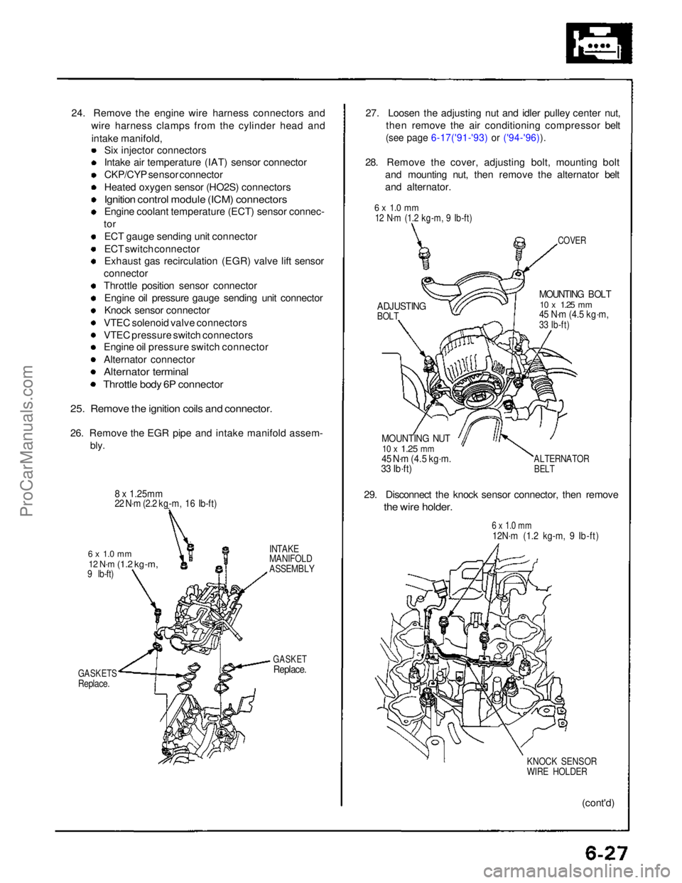
24. Remove the engine wire harness connectors and
wire harness clamps from the cylinder head and
intake manifold, Six injector connectors
Intake air temperature (IAT) sensor connector
CKP/CYP sensor connector
Heated oxygen sensor (HO2S) connectors
Ignition control module (ICM) connectors
Engine coolant temperature (ECT) sensor connec-
tor
ECT gauge sending unit connector
ECT switch connector
Exhaust gas recirculation (EGR) valve lift sensor
connector
Throttle position sensor connector Engine oil pressure gauge sending unit connector
Knock sensor connector
VTEC solenoid valve connectors
VTEC pressure switch connectors
Engine oil pressure switch connector
Alternator connector
Alternator terminal
Throttle body 6P connector
25. Remove the ignition coils and connector.
26. Remove the EGR pipe and intake manifold assem- bly.
8 x 1.25mm
22 N·m (2.2 kg-m, 16 Ib-ft)
6 x 1.0 mm
12 N·m
(1.2 kg-m,
9 lb-ft)
GASKETS
Replace. INTAKE
MANIFOLD
ASSEMBLY
GASKET
Replace.
27. Loosen the adjusting nut and idler pulley center nut,
then remove the air conditioning compressor belt
(see page 6-17('91-'93) or ('94-'96)).
28. Remove the cover, adjusting bolt, mounting bolt and mounting nut, then remove the alternator belt
and alternator.
COVER
MOUNTING BOLT
10 x
1.25
mm
45 N·m (4.5 kg·m,
33 Ib-ft)
MOUNTING NUT
10 x
1.25
mm
45 N·m (4.5 kg·m.
33 Ib·ft)
ALTERNATOR
BELT
29. Disconnect the knock sensor connector, then remove
the wire holder.
6 x 1.0 mm
12N·m (1.2 kg-m, 9 Ib-ft)
KNOCK SENSOR
WIRE HOLDER
(cont'd)
6 x 1.0 mm
12 N·m (1.2 kg-m, 9 Ib-ft)
ADJUSTING
BOLTProCarManuals.com
Page 162 of 1640
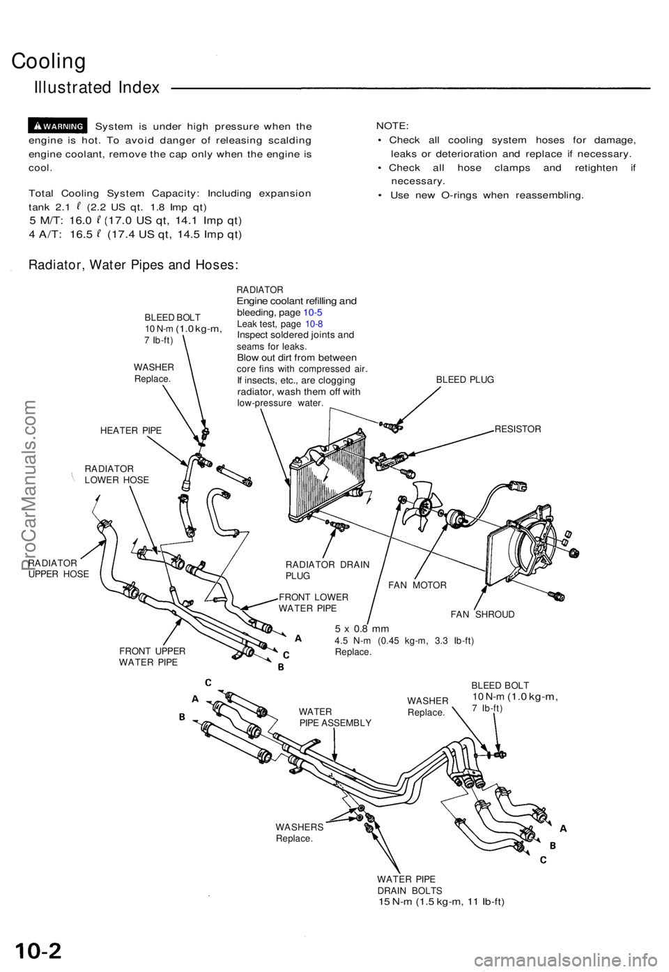
Cooling
Illustrated Index
Syste m is unde r hig h pressur e whe n th e
engin e i s hot . T o avoi d dange r o f releasin g scaldin g
engin e coolant , remov e th e ca p onl y whe n th e engin e i s
cool .
Tota l Coolin g Syste m Capacity : Includin g expansio n
tank 2. 1 (2. 2 U S qt . 1. 8 Im p qt )
5 M/T : 16. 0 (17. 0 US qt , 14. 1 Imp qt )
4 A/T : 16. 5 (17. 4 US qt , 14. 5 Imp qt )
NOTE :
• Chec k al l coolin g syste m hose s fo r damage ,
leak s o r deterioratio n an d replac e i f necessary .
• Chec k al l hos e clamp s an d retighte n i f
necessary .
• Us e ne w O-ring s whe n reassembling .
Radiator, Wate r Pipe s an d Hoses :
BLEED BOL T10 N- m (1. 0 kg-m ,7 Ib-ft )
WASHE RReplace .
HEATER PIP E
RADIATO R
LOWE R HOS E
RADIATO R
UPPE R HOS E
RADIATO REngine coolan t refillin g an dbleeding , pag e 10- 5Leak test , pag e 10- 8Inspec t soldere d joint s an dseam s fo r leaks .Blow ou t dir t fro m betwee ncore fin s wit h compresse d air .If insects , etc. , ar e cloggin gradiator, was h the m of f wit hlow-pressur e water . BLEE
D PLU G
RESISTO R
RADIATO R DRAI N
PLU G
FRON T LOWE R
WATE R PIP E
FRON T UPPE R
WATE R PIP E FA
N SHROU D
5 x 0. 8 m m4.5 N- m (0.4 5 kg-m , 3. 3 Ib-ft )
Replace .
BLEED BOL T
10 N- m (1. 0 kg-m ,7 Ib-ft )
WASHER S
Replace .
WATER PIP E
DRAI N BOLT S
15 N- m (1. 5 kg-m , 1 1 Ib-ft )
WATE RPIPE ASSEMBL YWASHE
RReplace .
FAN MOTO R
ProCarManuals.com
Page 165 of 1640
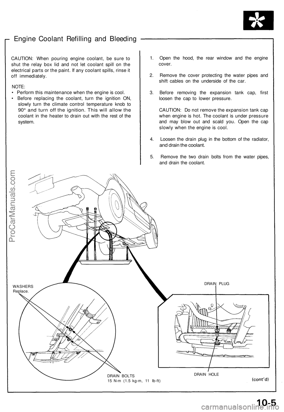
Engine Coolant Refilling and Bleeding
CAUTION: When pouring engine coolant, be sure to
shut the relay box lid and not let coolant spill on the
electrical parts or the paint. If any coolant spills, rinse it
off immediately.
NOTE:
• Perform this maintenance when the engine is cool.
• Before replacing the coolant, turn the ignition ON,
slowly turn the climate control temperature knob to
90° and turn off the ignition. This will allow the
coolant in the heater to drain out with the rest of the
system.
1. Open the hood, the rear window and the engine
cover.
2. Remove the cover protecting the water pipes and
shift cables on the underside of the car.
3. Before removing the expansion tank cap, first
loosen the cap to lower pressure.
CAUTION: Do not remove the expansion tank cap
when engine is hot. The coolant is under pressure
and may blow out and scald you. Open the cap
slowly when the engine is cool.
4. Loosen the drain plug in the bottom of the radiator,
and drain the coolant.
5. Remove the two drain bolts from the water pipes,
and drain the coolant.
WASHERS
Replace.
DRAIN BOLTS
15 N-m (1.5 kg-m, 11 Ib-ft)
DRAIN HOLE
DRAIN PLUGProCarManuals.com
Page 166 of 1640
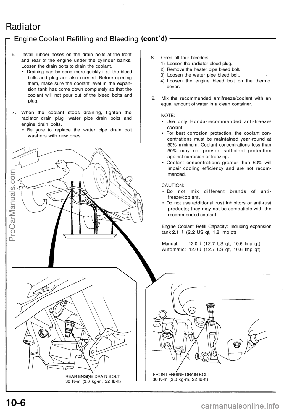
Radiator
Engine Coolan t Refillin g an d Bleedin g
6. Instal l rubbe r hose s o n th e drai n bolt s a t th e fron t
an d rea r of the engin e unde r th e cylinde r banks .
Loose n th e drai n bolt s t o drai n th e coolant .
• Drainin g ca n b e don e mor e quickl y i f al l th e blee d
bolt s an d plu g ar e als o opened . Befor e openin g
them , mak e sur e th e coolan t leve l i n th e expan -
sio n tan k ha s com e dow n completel y s o tha t th e
coolan t wil l no t pou r ou t o f th e blee d bolt s an d
plug .
7. Whe n th e coolan t stop s draining , tighte n th e
radiato r drai n plug , wate r pip e drai n bolt s an d
engin e drai n bolts .
• B e sur e t o replac e th e wate r pip e drai n bol t
washer s wit h ne w ones .
REAR ENGIN E DRAI N BOL T
3 0 N- m (3. 0 kg-m , 2 2 Ib-ft )
8. Ope n al l fou r bleeders .
1 ) Loose n th e radiato r blee d plug .
2 ) Remov e th e heate r pip e blee d bolt .
3 ) Loose n th e wate r pip e blee d bolt .
4 ) Loose n th e engin e blee d bol t o n th e therm o
cover.
9. Mi x th e recommende d antifreeze/coolan t wit h a n
equa l amoun t o f wate r i n a clea n container .
NOTE:
• Us e onl y Honda-recommende d anti-freeze /
coolant.
• Fo r bes t corrosio n protection , th e coolan t con -
centration s mus t b e maintaine d year-roun d a t
50 % minimum . Coolan t concentration s les s tha n
50 % ma y no t provid e sufficien t protectio n
agains t corrosio n o r freezing .
• Coolan t concentration s greate r tha n 60 % wil l
impai r coolin g efficienc y an d ar e no t recom -
mended.
CAUTION :
• D o no t mi x differen t brand s o f anti -
freeze/coolant .
• D o no t us e additiona l rus t inhibitor s o r anti-rus t
products ; the y ma y no t b e compatibl e wit h th e
recommende d coolant .
Engin e Coolan t Refil l Capacity : Includin g expansio n
tank 2. 1 (2. 2 U S qt , 1. 8 Im p qt )
Manual : 12. 0 (12. 7 U S qt , 10. 6 Im p qt )
Automatic : 12. 0 (12. 7 U S qt , 10. 6 Im p qt )
FRON T ENGIN E DRAI N BOL T30 N- m (3. 0 kg-m , 2 2 Ib-ft )
ProCarManuals.com
Page 167 of 1640
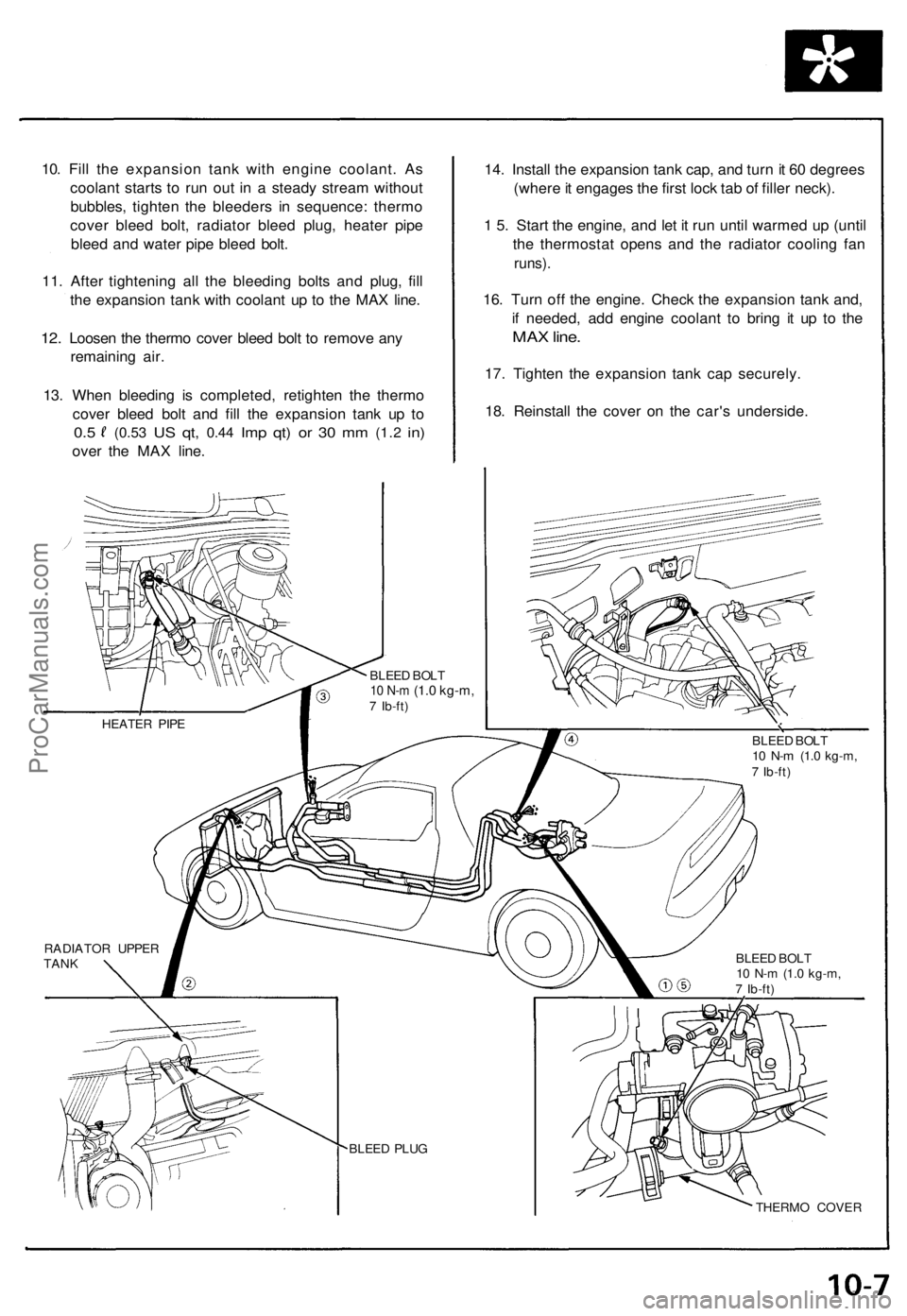
10. Fil l th e expansio n tan k wit h engin e coolant . A s
coolan t start s t o ru n ou t i n a stead y strea m withou t
bubbles , tighte n th e bleeder s i n sequence : therm o
cove r blee d bolt , radiato r blee d plug , heate r pip e
blee d an d wate r pip e blee d bolt .
11 . Afte r tightenin g al l th e bleedin g bolt s an d plug , fil l
th e expansio n tan k wit h coolan t u p t o th e MA X line .
12. Loose n th e therm o cove r blee d bol t t o remov e an y
remainin g air .
13 . Whe n bleedin g i s completed , retighte n th e therm o
cove r blee d bol t an d fill the expansio n tan k u p t o
0. 5 (0.5 3 US qt , 0.4 4 Imp qt ) o r 3 0 m m (1. 2 in)
ove r th e MA X line . 14
. Instal l th e expansio n tan k cap , an d tur n it 6 0 degree s
(wher e it engage s th e firs t loc k ta b o f fille r neck) .
1 5 . Star t th e engine , an d le t i t ru n unti l warme d u p (unti l
th e thermosta t open s an d th e radiato r coolin g fa n
runs) .
16. Tur n of f th e engine . Chec k th e expansio n tan k and ,
i f needed , ad d engin e coolan t t o brin g i t u p t o th e
MA X line .
17. Tighte n th e expansio n tan k ca p securely .
18 . Reinstal l th e cove r o n th e car' s underside .
THERMO COVE R
BLEE
D PLU G
RADIATO
R UPPE R
TAN K HEATE
R PIP E
BLEED BOL T
10 N- m (1. 0 kg-m ,7 Ib-ft )
BLEE
D BOL T
10 N- m (1. 0 kg-m ,7 Ib-ft )
BLEE
D BOL T
10 N- m (1. 0 kg-m ,7 Ib-ft )
ProCarManuals.com
Page 171 of 1640
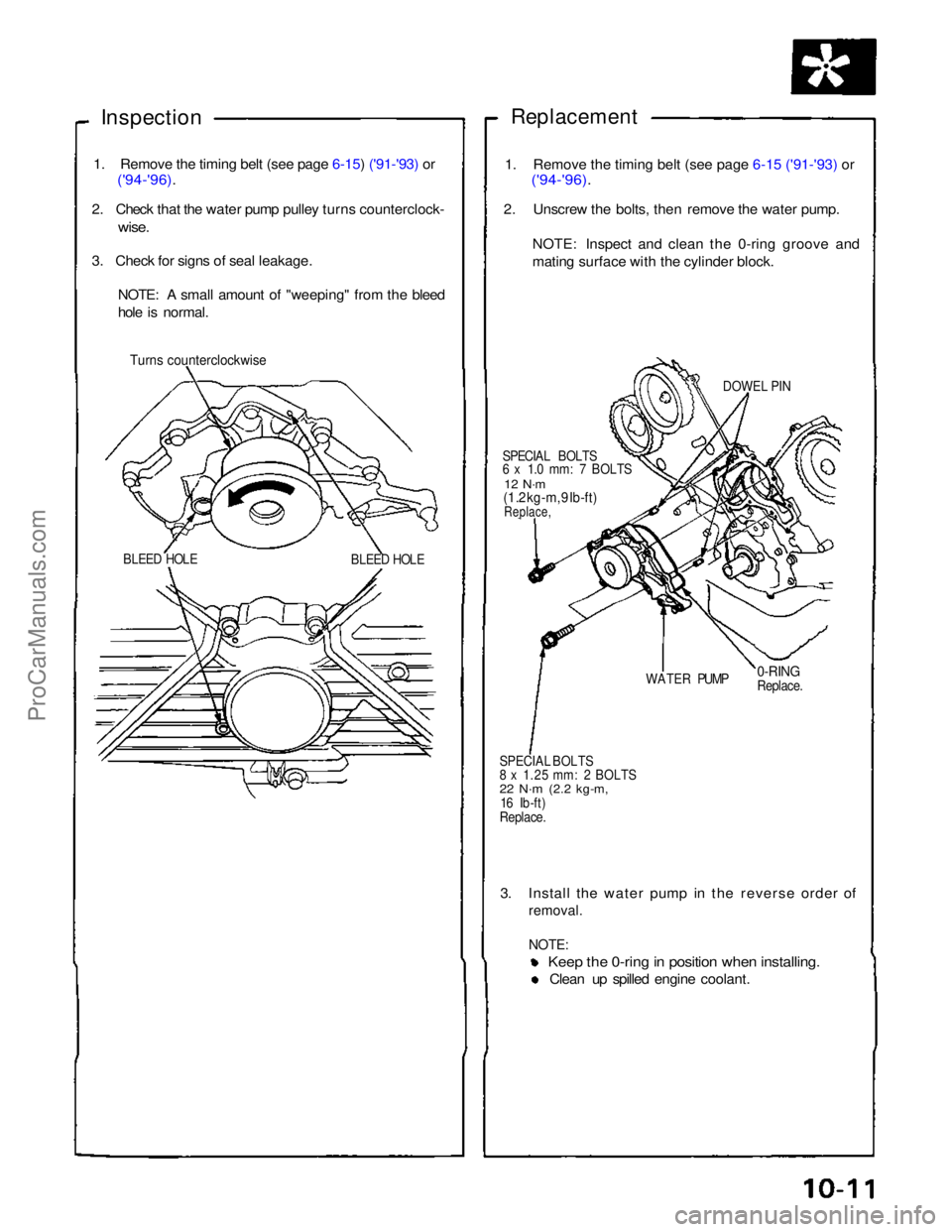
Inspection
Replacement
1. Remove the timing belt (see page 6-15) ('91-'93) or
('94-'96).
2. Check that the water pump pulley turns counterclock-
wise.
3. Check for signs of seal leakage.
NOTE: A small amount of "weeping" from the bleed
hole is normal.
Turns
counterclockwise
BLEED HOLE
BLEED HOLE
1. Remove the timing belt (see page 6-15 ('91-'93) or
('94-'96).
2. Unscrew the bolts, then remove the water pump.
NOTE: Inspect and clean the 0-ring groove and
mating surface with the cylinder block.
DOWEL PIN
SPECIAL BOLTS
6 x 1.0 mm: 7 BOLTS
12 N·m
(1 .2 kg-m, 9 Ib-ft)
Replace,
WATER PUMP
0-RING
Replace.
SPECIAL BOLTS
8 x 1.25 mm: 2 BOLTS
22 N·m
(2.2 kg-m,
16 Ib-ft)
Replace.
3. Install the water pump in the reverse order of
removal.
NOTE:
Keep the 0-ring in position when installing.
Clean up spilled engine coolant.ProCarManuals.com