lights ACURA NSX 1991 Service Repair Manual
[x] Cancel search | Manufacturer: ACURA, Model Year: 1991, Model line: NSX, Model: ACURA NSX 1991Pages: 1640, PDF Size: 60.48 MB
Page 230 of 1640
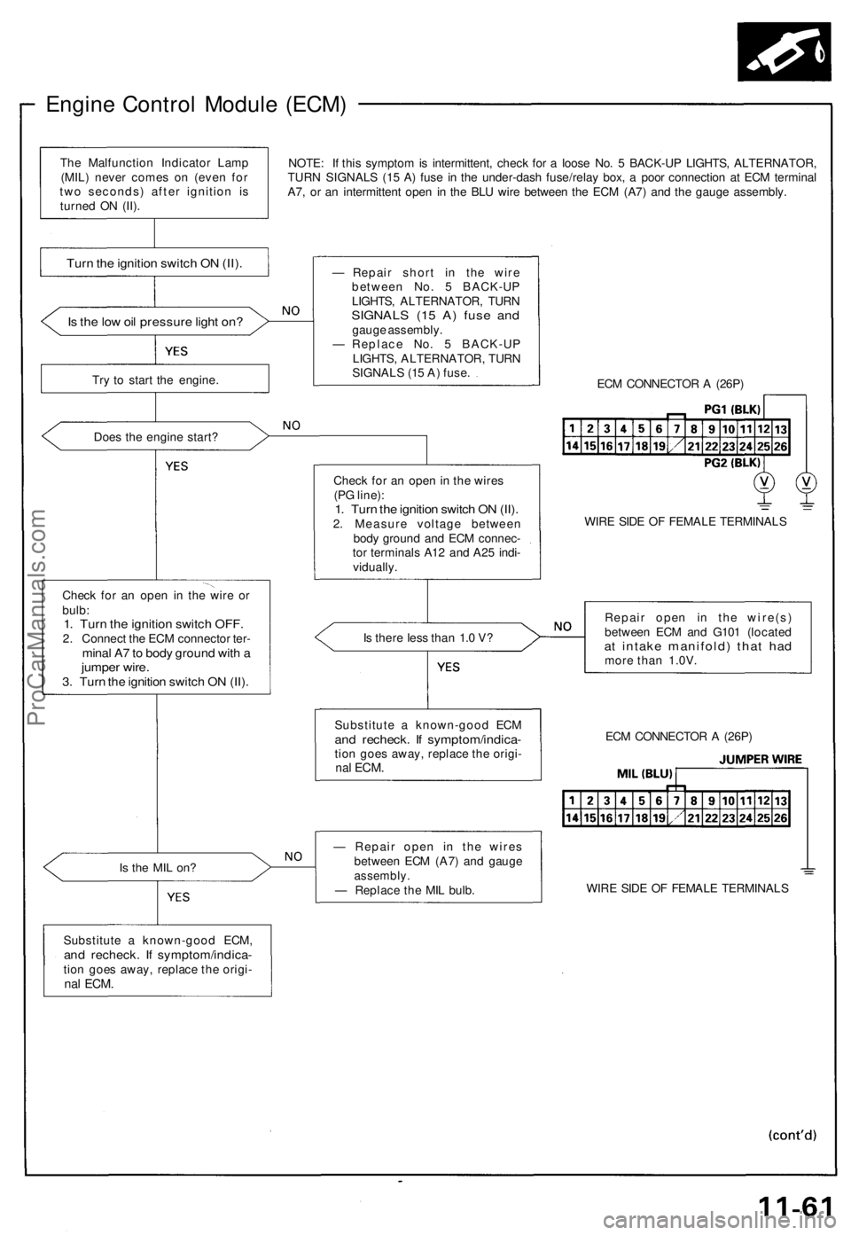
Engine Control Module (ECM)
NOTE: If this symptom is intermittent, check for a loose No. 5 BACK-UP LIGHTS, ALTERNATOR,
TURN SIGNALS (15 A) fuse in the under-dash fuse/relay box, a poor connection at ECM terminal
A7, or an intermittent open in the BLU wire between the ECM (A7) and the gauge assembly.
Is the low oil pressure light on?
Try to start the engine.
Does the engine start?
Check for an open in the wire or
bulb:
1. Turn the ignition switch OFF.
2. Connect the ECM connector ter-
minal A7 to body ground with a
jumper wire.
3. Turn the ignition switch ON (II).
Is the MIL on?
Substitute a known-good ECM,
and recheck. If symptom/indica-
tion goes away, replace the origi-
nal
ECM.
— Repair short in the wire
between No. 5 BACK-UP
LIGHTS, ALTERNATOR, TURN
SIGNALS (15 A) fuse and
gauge assembly.
— Replace No. 5 BACK-UP
LIGHTS, ALTERNATOR, TURN
SIGNALS (15 A) fuse.
ECM CONNECTOR A (26P)
Check for an open in the wires
(PG line):
1. Turn the ignition switch ON (II).
2. Measure voltage between
body ground and ECM connec-
tor terminals A12 and A25 indi-
vidually.
WIRE SIDE OF FEMALE TERMINALS
Is there less than 1.0 V?
Repair open in the wire(s)
between ECM and G101 (located
at intake manifold) that had
more than 1.0V.
— Repair open in the wires
between ECM (A7) and gauge
assembly.
— Replace the MIL bulb.
WIRE SIDE OF FEMALE TERMINALS
ECM CONNECTOR A (26P)
Substitute a known-good ECM
and recheck. If symptom/indica-
tion goes away, replace the origi-
nal
ECM.
Turn the ignition switch ON (II).
The Malfunction Indicator Lamp
(MIL) never comes on (even for
two seconds) after ignition is
turned ON (II).ProCarManuals.com
Page 247 of 1640
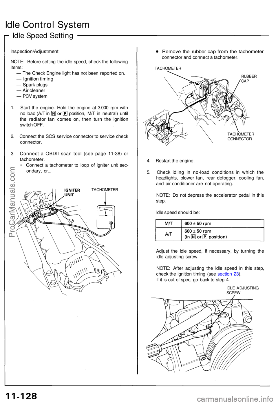
Idle Contro l Syste m
Idle Spee d Settin g
Inspection/Adjustmen t
NOTE: Befor e settin g th e idl e speed , chec k th e followin g
items :
— Th e Chec k Engin e ligh t ha s no t bee n reporte d on .
— Ignitio n timin g
— Spar k plug s
— Ai r cleane r
— PC V syste m
1 . Star t th e engine . Hol d th e engin e a t 3,00 0 rp m wit h
no loa d (A/ T in position , M/ T in neutral ) unti l
th e radiato r fa n come s on , the n tur n th e ignitio n
switc h OFF .
2 . Connec t th e SC S servic e connecto r t o servic e chec k
connector .
3. Connec t a OBDI I sca n too l (se e pag e 11-38 ) o r
tachometer .
• Connec t a tachomete r t o loo p o f ignite r uni t sec -
ondary , or.. .
TACHOMETE R
Remove th e rubbe r ca p fro m th e tachomete r
connector an d connec t a tachometer .
TACHOMETE R
RUBBERCAP
TACHOMETE RCONNECTOR
4. Restar t th e engine .
5 . Chec k idlin g i n no-loa d condition s i n whic h th e
headlights , blowe r fan , rea r defogger , coolin g fan ,
an d ai r conditione r ar e no t operating .
NOTE : D o no t depres s th e accelerato r peda l i n thi s
step .
Idl e spee d shoul d be :
Adjus t th e idl e speed , i f necessary , b y turnin g th e
idl e adjustin g screw .
NOTE : Afte r adjustin g th e idl e spee d i n thi s step ,
chec k th e ignitio n timin g (se e sectio n 23 ).
I f i t i s ou t o f spec , g o bac k t o ste p 4 .
IDL E ADJUSTIN GSCREW
ProCarManuals.com
Page 268 of 1640
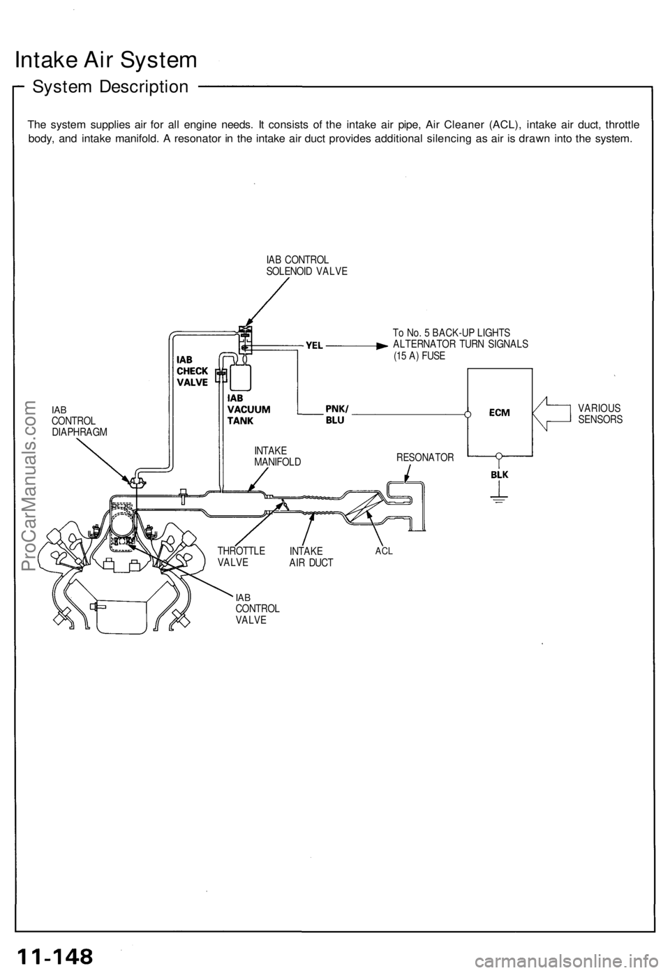
Intake Air System
System Description
The system supplies air for all engine needs. It consists of the intake air pipe, Air Cleaner (ACL), intake air duct, throttle
body, and intake manifold. A resonator in the intake air duct provides additional silencing as air is drawn into the system.
IAB CONTROL
SOLENOID VALVE
To No. 5 BACK-UP LIGHTS
ALTERNATOR TURN SIGNALS
(15 A) FUSE
IAB
CONTROL
DIAPHRAGM
IAB
CONTROL
VALVE
THROTTLE
VALVE
INTAKE
AIR DUCT
ACL
RESONATOR
VARIOUS
SENSORS
INTAKE
MANIFOLDProCarManuals.com
Page 274 of 1640
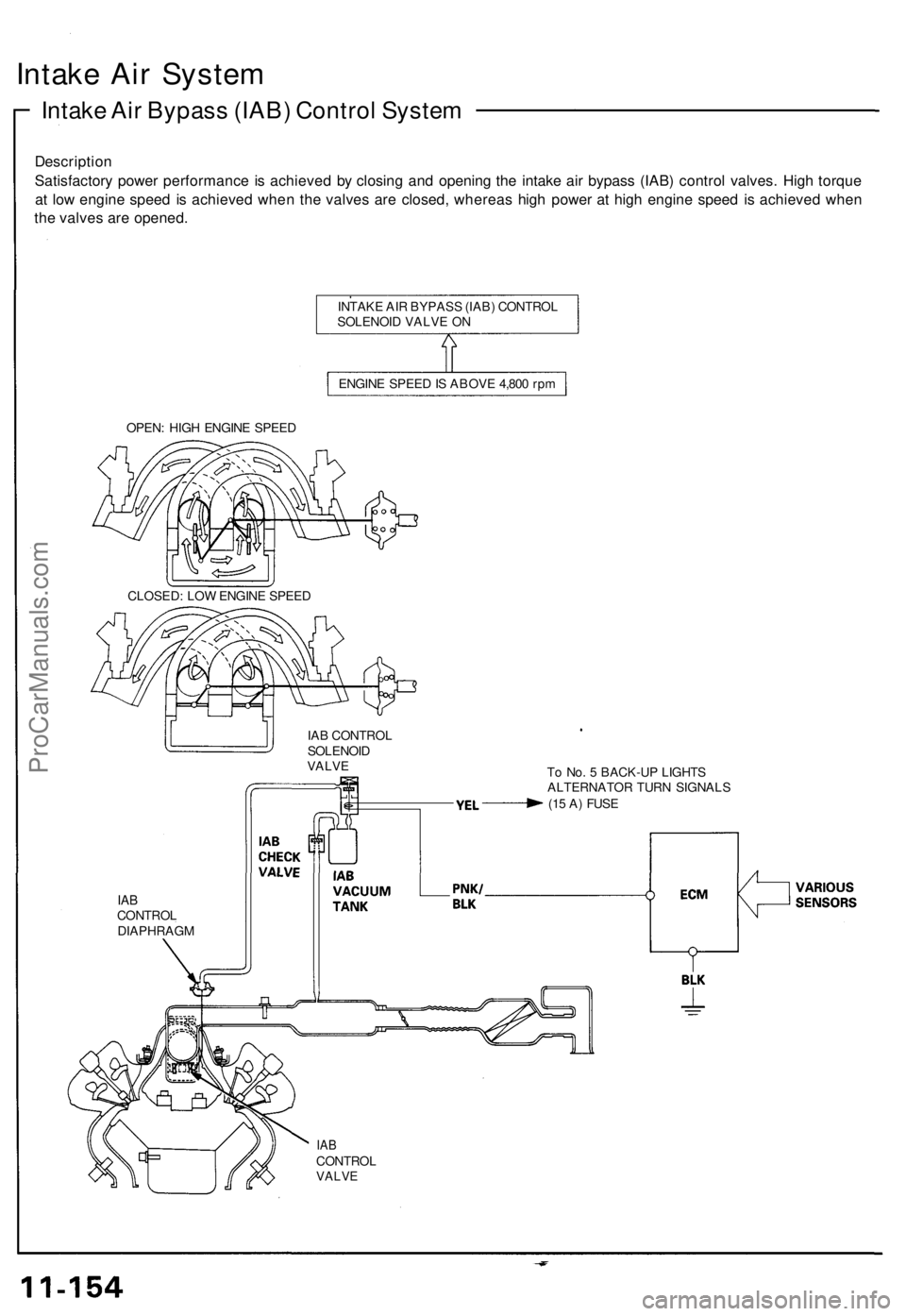
Intake Air System
Intake Air Bypass (IAB) Control System
Description
Satisfactory power performance is achieved by closing and opening the intake air bypass (IAB) control valves. High torque
at low engine speed is achieved when the valves are closed, whereas high power at high engine speed is achieved when
the valves are opened.
INTAKE AIR BYPASS (IAB) CONTROL
SOLENOID VALVE ON
ENGINE SPEED IS ABOVE 4,800 rpm
OPEN: HIGH ENGINE SPEED
IAB CONTROL
SOLENOID
VALVE
To No. 5 BACK-UP LIGHTS
ALTERNATOR TURN SIGNALS
(15 A) FUSE
IAB
CONTROL
DIAPHRAGM
IAB
CONTROL
VALVE
CLOSED: LOW ENGINE SPEEDProCarManuals.com
Page 276 of 1640
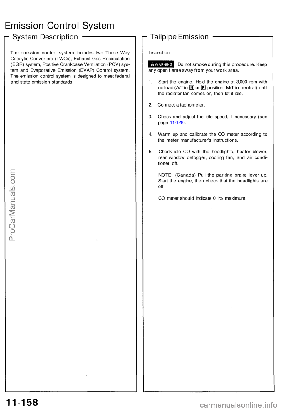
Emission Contro l Syste m
System Descriptio n
The emissio n contro l syste m include s tw o Thre e Wa y
Catalyti c Converter s (TWCs) , Exhaus t Ga s Recirculatio n
(EGR ) system , Positiv e Crankcas e Ventilatio n (PCV ) sys -
te m an d Evaporativ e Emissio n (EVAP ) Contro l system .
Th e emissio n contro l syste m is designe d t o mee t federa l
an d stat e emissio n standards .
Tailpipe Emissio n
Inspectio n
Do no t smok e durin g thi s procedure . Kee p
an y ope n flam e awa y fro m you r wor k area .
1 . Star t th e engine . Hol d th e engin e a t 3,00 0 rp m wit h
no loa d (A/ T in position , M/ T in neutral ) unti l
the radiato r fa n come s on , the n le t i t idle .
2 . Connec t a tachometer .
3 . Chec k an d adjus t th e idl e speed , i f necessar y (se e
pag e 11-128 ).
4 . War m u p an d calibrat e th e C O mete r accordin g t o
th e mete r manufacturer' s instructions .
5 . Chec k idl e C O wit h th e headlights , heate r blower ,
rea r windo w defogger , coolin g fan , an d ai r condi -
tione r off .
NOTE : (Canada ) Pul l th e parkin g brak e leve r up .
Star t th e engine , the n chec k tha t th e headlight s ar e
off.
CO mete r shoul d indicat e 0.1 % maximum .
ProCarManuals.com
Page 280 of 1640
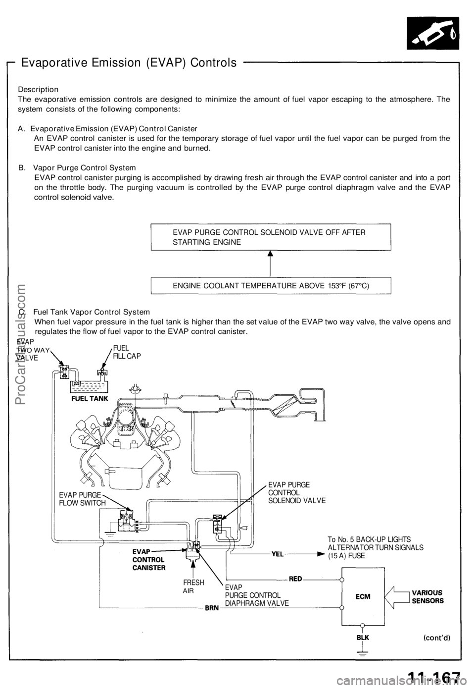
Evaporative Emission (EVAP) Controls
Description
The evaporative emission controls are designed to minimize the amount of fuel vapor escaping to the atmosphere. The
system consists of the following components:
A. Evaporative Emission (EVAP) Control Canister
An EVAP control canister is used for the temporary storage of fuel vapor until the fuel vapor can be purged from the
EVAP control canister into the engine and burned.
B. Vapor Purge Control System
EVAP control canister purging is accomplished by drawing fresh air through the EVAP control canister and into a port
on the throttle body. The purging vacuum is controlled by the EVAP purge control diaphragm valve and the EVAP
control solenoid valve.
EVAP PURGE CONTROL SOLENOID VALVE OFF AFTER
STARTING ENGINE
ENGINE COOLANT TEMPERATURE ABOVE 153°F (67°C)
To No. 5 BACK-UP LIGHTS
ALTERNATOR TURN SIGNALS
(15 A) FUSE
FRESH
AIR
EVAP
PURGE CONTROL
DIAPHRAGM VALVE
EVAP PURGE
CONTROL
SOLENOID VALVE
EVAP PURGE
FLOW SWITCH
C. Fuel Tank Vapor Control System
When fuel vapor pressure in the fuel tank is higher than the set value of the EVAP two way valve, the valve opens and
regulates the flow of fuel vapor to the EVAP control canister.
EVAP
TWO WAY
VALVE
FUEL
FILL CAPProCarManuals.com
Page 546 of 1640
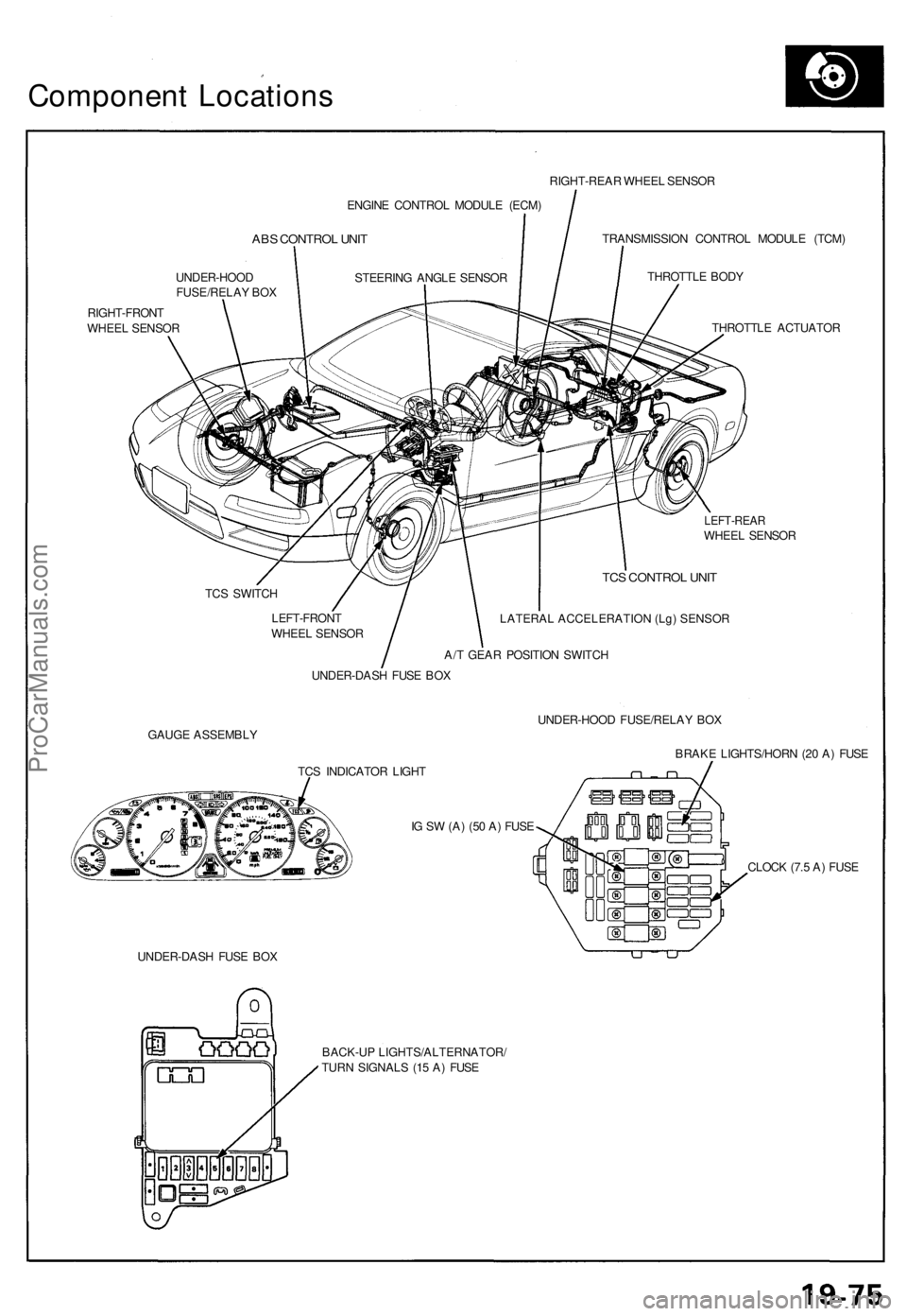
Component Location s
ENGINE CONTRO L MODUL E (ECM )
ABS CONTRO L UNI T
UNDER-HOO D
FUSE/RELA Y BO X
RIGHT-FRON T
WHEE L SENSO R RIGHT-REA
R WHEE L SENSO R
TRANSMISSIO N CONTRO L MODUL E (TCM )
THROTTL E BOD Y
THROTTL E ACTUATO R
LEFT-REARWHEEL SENSO R
TC S SWITC H
LEFT-FRON T
WHEE L SENSO R
TCS CONTRO L UNI T
LATERAL ACCELERATION (Lg) SENSOR
A/T GEA R POSITIO N SWITC H
UNDER-DAS H FUS E BO X
GAUG E ASSEMBL Y UNDER-HOO
D FUSE/RELA Y BO X
BRAK E LIGHTS/HOR N (2 0 A ) FUS E
TC S INDICATO R LIGH T
I G S W (A ) (5 0 A ) FUS E
UNDER-DAS H FUS E BO X CLOC
K (7. 5 A ) FUS E
BACK-U P LIGHTS/ALTERNATOR /
TUR N SIGNAL S (1 5 A ) FUS E
STEERIN
G ANGL E SENSO R
ProCarManuals.com
Page 685 of 1640
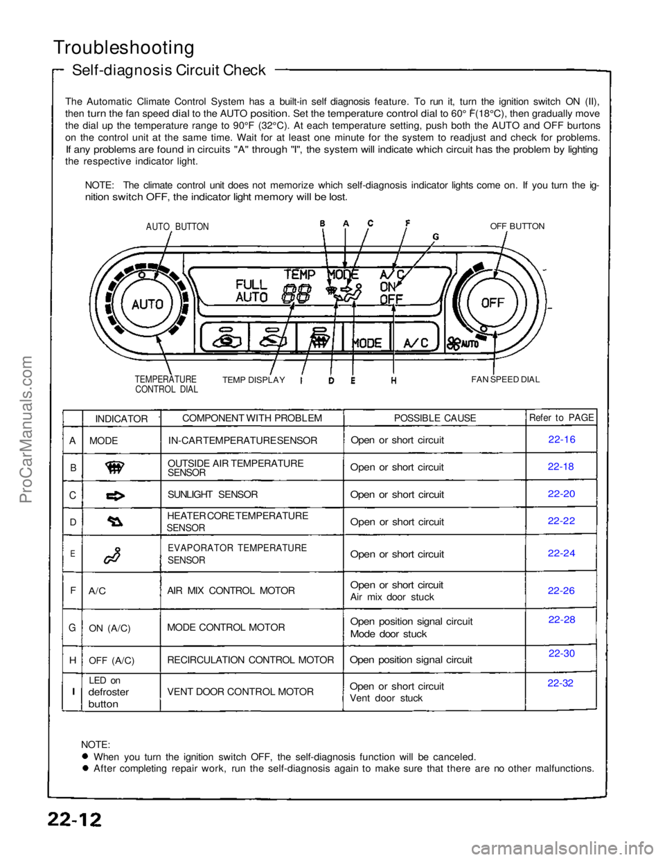
Troubleshooting
Self-diagnosis Circuit Check
The Automatic Climate Control System has a built-in self diagnosis feature. To run it, turn the ignition switch ON (II),
then turn the fan speed dial to the AUTO position. Set the temperature control dial to 60° F(18°C), then gradually move
0
th
e
dial up the temperature range to 90°F (32°C). At each temperatu\
re setting, push both the AUTO and OFF burtons
o
n
the control unit at the same time. Wait for at least one minute for the\
system to readjust and check for problems.
If any problems are found in circuits "A" through "I", the system will indicate which circuit has the problem by lighting
the respective indicator light.
NOTE: The climate control unit does not memorize which self-diagnosis indicator lights come on. If you turn the ig-
nition switch OFF, the indicator light memory will be lost.
AUTO BUTTON
OFF BUTTON
TEMPERATURE CONTROL DIAL
TEMP DISPLAY
FAN SPEED DIAL
NOTE:
When you turn the ignition switch OFF, the self-diagnosis function will be canceled. After completing repair work, run the self-diagnosis again to make sure that there are no other malfunctions.COMPONENT WITH PROBLEM
IN-CAR TEMPERATURE SENSOR
OUTSIDE AIR TEMPERATURE
SENSOR
SUNLIGHT SENSOR
HEATER CORE TEMPERATURE
SENSOR
EVAPORATOR TEMPERATURE
SENSOR
AIR MIX CONTROL MOTOR
MODE CONTROL MOTOR
RECIRCULATION CONTROL MOTOR
VENT DOOR CONTROL MOTOR
POSSIBLE CAUSE
Open or short circuit
Open or short circuit
Open or short circuit
Open or short circuit
Open or short circuit
Open or short circuit
Air mix door stuck
Open position signal circuit
Mode door stuck
Open position signal circuit
Open or short circuit
Vent door stuck
Refer to PAGE
22-16
22-1
8
22-20
22-22
22-24
22-2
6
22-28
22-30
22-32
INDICATOR
MODE
A/C
ON
(A/C)
OFF
(A/C)
LED on
defroster
button
A
B
C
D
E
F
G
H
I
ProCarManuals.com
Page 734 of 1640
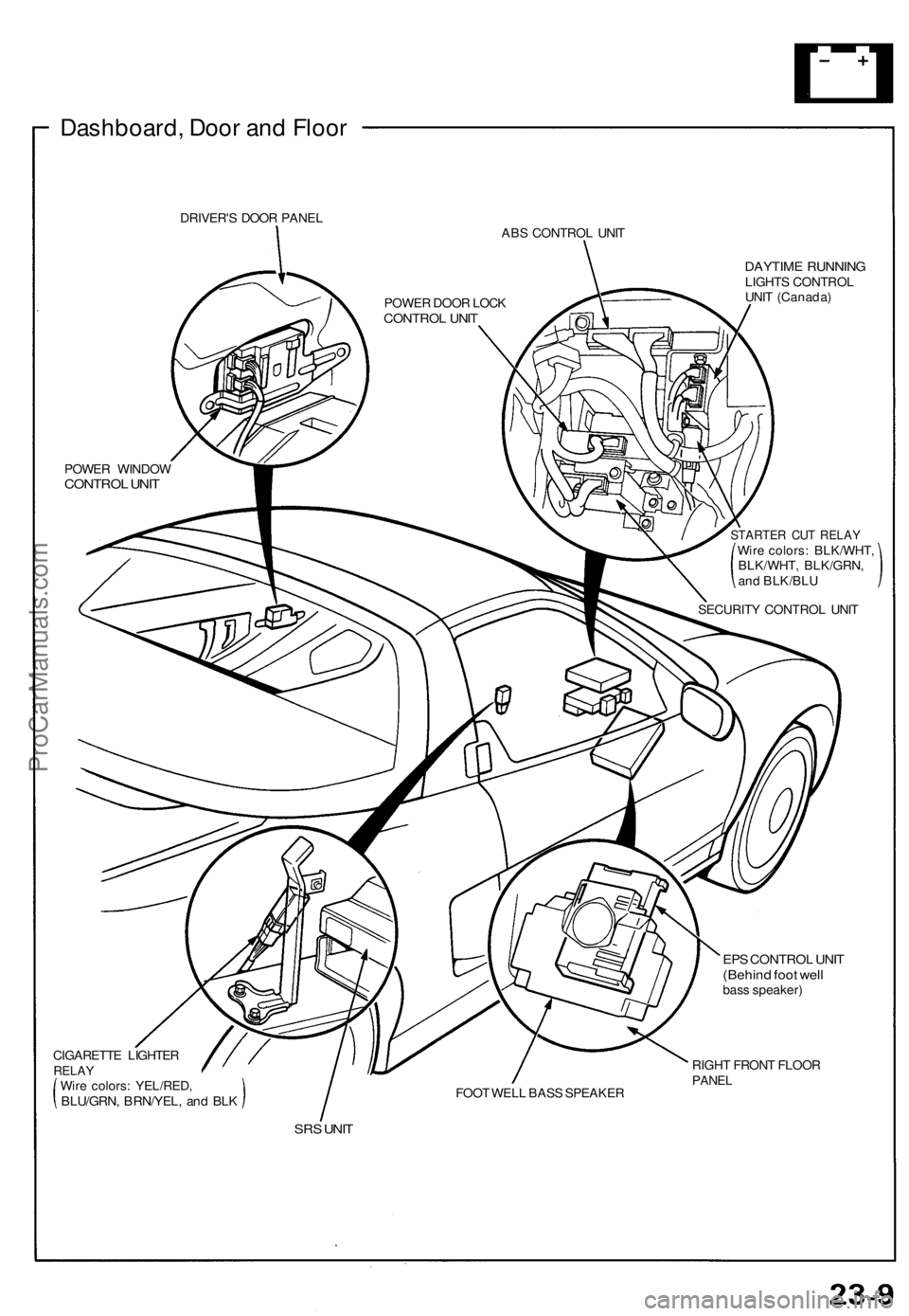
Dashboard, Door and Floor
DRIVER'S DOOR PANEL
ABS CONTROL UNIT
DAYTIME RUNNING
LIGHTS CONTROL
UNIT (Canada)
POWER WINDOW
CONTROL UNIT
STARTER CUT RELAY
Wire colors: BLK/WHT,
BLK/WHT, BLK/GRN,
and BLK/BLU
SECURITY CONTROL UNIT
CIGARETTE LIGHTER
RELAY
Wire colors: YEL/RED,
BLU/GRN, BRN/YEL, and BLK
FOOT WELL BASS SPEAKER
EPS CONTROL UNIT
(Behind foot well
bass speaker)
RIGHT FRONT FLOOR
PANEL
SRS UNIT
POWER DOOR LOCK
CONTROL UNITProCarManuals.com
Page 735 of 1640
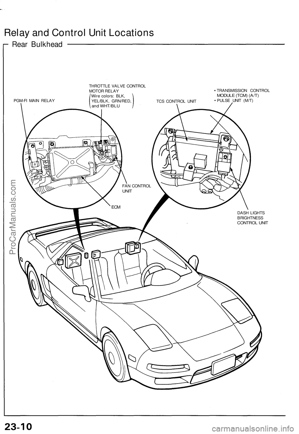
Relay and Control Unit Locations
Rear Bulkhead
PGM-FI MAIN RELAY
THROTTLE VALVE CONTROL
MOTOR RELAY
Wire colors: BLK,
YEL/BLK, GRN/RED,
and WHT/BLU
TCS CONTROL UNIT
TRANSMISSION CONTROL
MODULE (TCM) (A/T)
PULSE UNIT (M/T)
DASH LIGHTS
BRIGHTNESS
CONTROL UNIT
FAN CONTROL
UNIT
ECMProCarManuals.com