remove seats ACURA NSX 1991 Service Repair Manual
[x] Cancel search | Manufacturer: ACURA, Model Year: 1991, Model line: NSX, Model: ACURA NSX 1991Pages: 1640, PDF Size: 60.48 MB
Page 39 of 1640
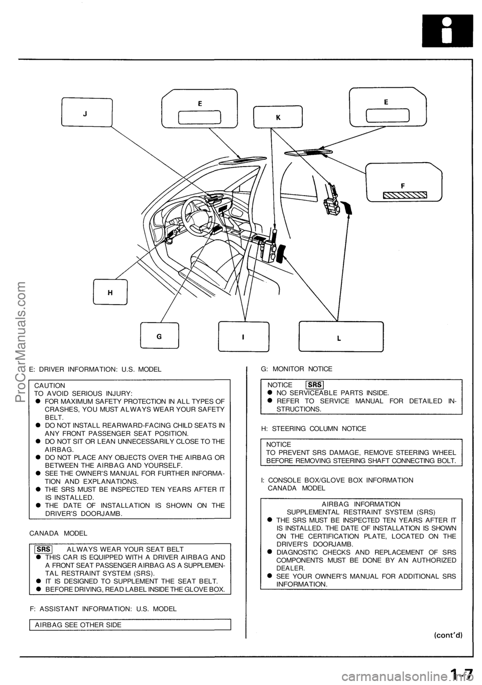
E: DRIVER INFORMATION: U.S. MODEL
CAUTION
TO AVOID SERIOUS INJURY:
FOR MAXIMUM SAFETY PROTECTION IN ALL TYPES OF
CRASHES, YOU MUST ALWAYS WEAR YOUR SAFETY
BELT.
DO NOT INSTALL REARWARD-FACING CHILD SEATS IN
ANY FRONT PASSENGER SEAT POSITION.
DO NOT SIT OR LEAN UNNECESSARILY CLOSE TO THE
AIRBAG.
DO NOT PLACE ANY OBJECTS OVER THE AIRBAG OR
BETWEEN THE AIRBAG AND YOURSELF.
SEE THE OWNER'S MANUAL FOR FURTHER INFORMA-
TION AND EXPLANATIONS.
THE SRS MUST BE INSPECTED TEN YEARS AFTER IT
IS INSTALLED.
THE DATE OF INSTALLATION IS SHOWN ON THE
DRIVER'S DOORJAMB.
CANADA MODEL
ALWAYS WEAR YOUR SEAT BELT
THIS CAR IS EQUIPPED WITH A DRIVER AIRBAG AND
A FRONT SEAT PASSENGER AIRBAG AS A SUPPLEMEN-
TAL RESTRAINT SYSTEM (SRS).
IT IS DESIGNED TO SUPPLEMENT THE SEAT BELT.
BEFORE DRIVING, READ LABEL INSIDE THE GLOVE BOX.
F: ASSISTANT INFORMATION: U.S. MODEL
AIRBAG SEE OTHER SIDE
G: MONITOR NOTICE
NOTICE
NO SERVICEABLE PARTS INSIDE.
REFER TO SERVICE MANUAL FOR DETAILED IN-
STRUCTIONS.
H: STEERING COLUMN NOTICE
NOTICE
TO PREVENT SRS DAMAGE, REMOVE STEERING WHEEL
BEFORE REMOVING STEERING SHAFT CONNECTING BOLT.
I: CONSOLE BOX/GLOVE BOX INFORMATION
CANADA MODEL
AIRBAG INFORMATION
SUPPLEMENTAL RESTRAINT SYSTEM (SRS)
THE SRS MUST BE INSPECTED TEN YEARS AFTER IT
IS INSTALLED. THE DATE OF INSTALLATION IS SHOWN
ON THE CERTIFICATION PLATE, LOCATED ON THE
DRIVER'S DOORJAMB.
DIAGNOSTIC CHECKS AND REPLACEMENT OF SRS
COMPONENTS MUST BE DONE BY AN AUTHORIZED
DEALER.
SEE YOUR OWNER'S MANUAL FOR ADDITIONAL SRS
INFORMATION.ProCarManuals.com
Page 581 of 1640
Windshield
Removal
CAUTION: Wear gloves to remove and install the windshield. Use covers to avoid damaging any surfaces.
1. To remove the windshield, first remove the: Seats (see page 20-39('93-'96)('91-'92)
Rearview mirror (see page 20-46('93-'96)('91-'92)
Sunvisors (see page 20-38('93-'96),37('91-'92)
Front pillar retainer (see page 20-21('93-'96),20('91-'92)
Front wiper and air scoop (see section 23)
Front pillar trim and headliner (see page 20-38
('93-'96),37('91-'92)
2. Peel off the upper molding.
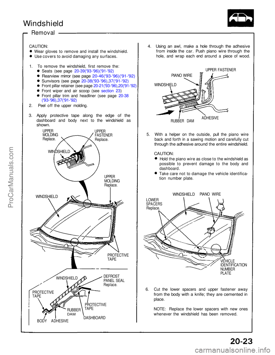
3. Apply protective tape along the edge of the
dashboard and body next to the windshield as
shown.
UPPER
MOLDING
Replace.
UPPER
FASTENER
Replace.
WINDSHIELD
UPPER
MOLDING
Replace.
WINDSHIELD
PROTECTIVE
TAPE
WINDSHIELD
DEFROST
PANEL SEAL
Replace.
PROTECTIVE
TAPE
BODY
ADHESIVE
RUBBER
DAM
DASHBOARD
PROTECTIVE
TAPE
4. Using an awl, make a hole through the adhesive
from inside the car. Push piano wire through the
hole, and wrap each end around a piece of wood.
UPPER FASTENER
PIANO WIRE
WINDSHIELD
ADHESIVE
RUBBER DAM
5. With a helper on the outside, pull the piano wire back and forth in a sawing motion and carefully cut
through the adhesive around the entire windshield.
CAUTION:
Hold the piano wire as close to the windshield as
possible to prevent damage to the body and
dashboard.
Take care not to damage the vehicle identifica-
tion number plate.
WINDSHIELD
PIANO WIRE
LOWER
SPACERS
Replace.
VEHICLE
IDENTIFICATION
NUMBER
PLATE
6. Cut the lower spacers and upper fastener away
from the body with a knife; they are cemented in
place.
NOTE: Replace the lower spacers with new ones
whenever the windshield has been removed.ProCarManuals.com
Page 586 of 1640
Rear Window
Removal
CAUTION: Wear gloves to remove and install the rear window.
Since the rear window is double glazed glass with the
Inner glass (interior-side) larger than the outer glass,
care should be taken not to damege the edge of the
inner glass when removing the outer glass.
To remove the rear window, first remove: Seats (see page 20-39('93-'96),('91-'92)
Center pillar trim panel (see page 20-38)('93-'96),37('91-'92)
Rear upper trim panel (see page 20-38)
('93-'96),37('91-'92)
Rear hatch assembly (see page 20-64('93-'96),53('91-'92)
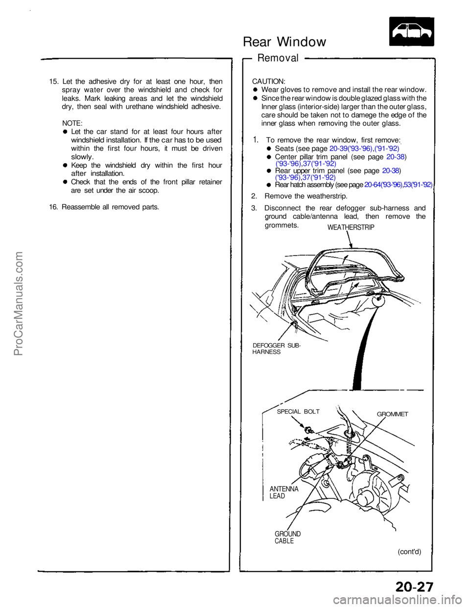
2. Remove the weatherstrip.
3. Disconnect the rear defogger sub-harness and
ground cable/antenna lead, then remove the
grommets.
WEATHERSTRIP
DEFOGGER SUB-
HARNESS
GROMMET
(cont'd)
GROUND
CABLE
ANTENNA
LEAD
SPECIAL BOLT
15. Let the adhesive dry for at least one hour, then
spray water over the windshield and check for
leaks. Mark leaking areas and let the windshield
dry, then seal with urethane windshield adhesive.
NOTE:
Let the car stand for at least four hours after
windshield installation. If the car has to be used
within the first four hours, it must be driven
slowly.
Keep the windshield dry within the first hour
after installation.
Check that the ends of the front pillar retainer
are set under the air scoop.
16. Reassemble all removed parts.
1.ProCarManuals.com
Page 595 of 1640
Headliner/lnterior Trim
Replacement
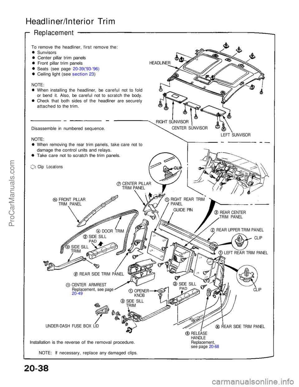
To remove the headliner, first remove the: Sunvisors
Center pillar trim panels
Front pillar trim panels
Seats (see page 20-39('93-'96)
Ceiling light (see section 23)
NOTE:
When installing the headliner, be careful not to fold
or bend it. Also, be careful not to scratch the body.
Check that both sides of the headliner are securely
attached to the trim.
Disassemble in numbered sequence.
NOTE: When removing the rear trim panels, take care not to
damage the control units and relays.
Take care not to scratch the trim panels.
Clip Locations
CENTER PILLAR
TRIM PANEL
FRONT PILLAR
TRIM PANEL
DOOR TRIM
SIDE SILL
PAD
SIDE SILL
TRIM
REAR SIDE TRIM PANEL
CENTER ARMREST
Replacement, see page
20-49
OPENER
KNOB
SIDE SILL
TRIM
UNDER-DASH FUSE BOX LID
Installation is the reverse of the removal procedure.
NOTE: If necessary, replace any damaged clips.
RELEASE
HANDLE
Replacement,
see page 20-68
REAR SIDE TRIM PANEL CLIP
SIDE SILL
PAD
LEFT REAR TRIM PANEL
CLIP
REAR UPPER TRIM PANEL REAR CENTER
TRIM PANEL
GUIDE PIN
RIGHT REAR TRIM
PANEL LEFT SUNVISOR
CENTER SUNVISOR
RIGHT SUNVISOR
HEADLINERProCarManuals.com
Page 597 of 1640
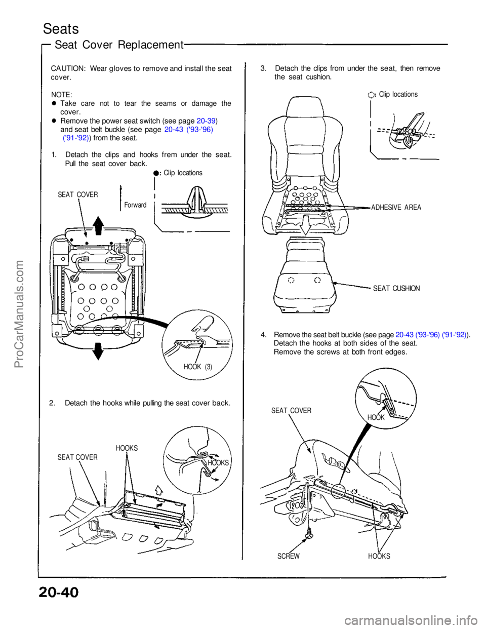
Seats
Seat Cover Replacement
CAUTION: Wear gloves to remove and install the seat
cover.
NOTE:
Take care not to tear the seams or damage the
cover.
Remove the power seat switch (see page 20-39)
and seat belt buckle (see page 20-43 ('93-'96) ('91-'92)) from the seat.
1. Detach the clips and hooks frem under the seat.
Pull the seat cover back.
Clip locations
SEAT COVER Forward
HOOK (3)
2. Detach the hooks while pulling the seat cover back.
SEAT COVER HOOKS
HOOKS
SCREW
HOOKS
SEAT COVER
HOOK
4. Remove the seat belt buckle (see page 20-43 ('93-'96) ('91-'92)).
Detach the hooks at both sides of the seat.
Remove the screws at both front edges.
SEAT CUSHION
ADHESIVE AREA
Clip locations
3. Detach the clips from under the seat, then remove
the seat cushion.ProCarManuals.com
Page 604 of 1640
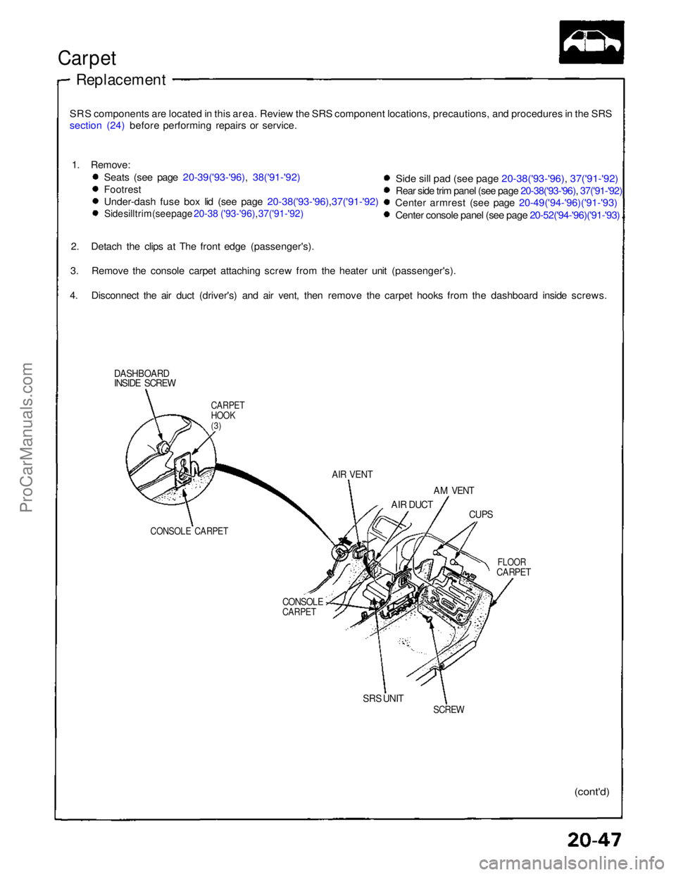
Carpet
Replacement
SRS components are located in this area. Review the SRS component locations, precautions, and procedures in the SRS
section (24) before performing repairs or service.
DASHBOARD
INSIDE SCREW
CARPET
HOOK
(3)
AIR VENT
AM VENT
AIR DUCT
CUPS
FLOOR
CARPET
CONSOLE
CARPET
CONSOLE CARPET
SRS UNIT
SCREW
(cont'd)
1. Remove:
Seats (see page 20-39('93-'96), 38('91-'92)
Footrest
Under-dash fuse box lid (see page 20-38('93-'96),37('91-'92)
Side sill trim (see page 20-38 ('93-'96), 37('91-'92)
Side sill pad (see page 20-38('93-'96), 37('91-'92)
Rear side trim panel (see page 20-38('93-'96), 37('91-'92)
Center armrest (see page 20-49('94-'96)('91-'93)
Center console panel (see page 20-52('94-'96)('91-'93)
2. Detach the clips at The front edge (passenger's).
3. Remove the console carpet attaching screw from the heater unit (passenger's).
4. Disconnect the air duct (driver's) and air vent, then remove the carpet hooks from the dashboard inside screws.ProCarManuals.com
Page 612 of 1640
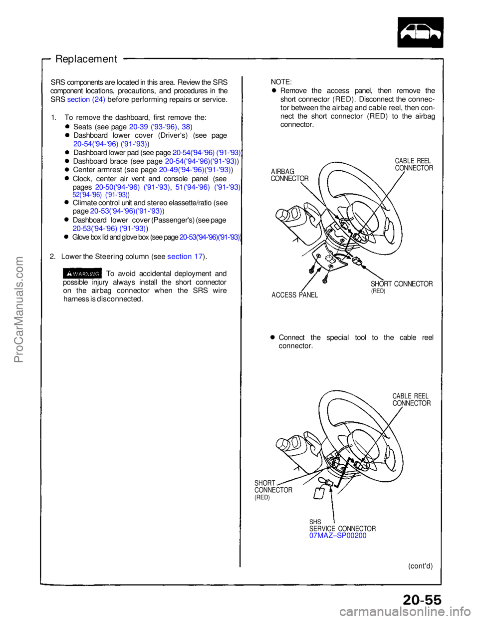
Replacement
NOTE:
Remove the access panel, then remove the
short connector (RED). Disconnect the connec-
tor between the airbag and cable reel, then con-
nect the short connector (RED) to the airbag
connector.
AIRBAG
CONNECTOR
CABLE REEL
CONNECTOR
ACCESS PANEL
SHORT CONNECTOR
(RED)
Connect the special tool to the cable reel
connector.
CABLE REEL
CONNECTOR
SHORT
CONNECTOR
(RED)
SHS
SERVICE CONNECTOR
07MAZ–SP00200
(cont'd)
SRS components are located in this area. Review the SRS
component locations, precautions, and procedures in the
SRS section (24) before performing repairs or service.
1. To remove the dashboard, first remove the: Seats (see page 20-39 ('93-'96), 38)
Dashboard lower cover (Driver's) (see page
20-54('94-'96) ('91-'93))
Dashboard lower pad (see page 20-54('94-'96) ('91-'93))
Dashboard brace (see page 20-54('94-'96)('91-'93))
Cente
r
armrest (see page 20-49('94-'96)('91-'93))
Clock, center air vent and console panel (see
pages 20-50('94-'96) ('91-'93), 51('94-'96) ('91-'93)
52('94-'96) ('91-'93))
Climate control unit and stereo elassette/ratio (see
page 20-53('94-'96)('91-'93))
Dashboard lower cover (Passenger's) (see page
20-53('94-'96) ('91-'93))
Glove box lid and glove box (see page 20-53('94-'96)('91-'93))
2. Lower the Steering column (see section 17).
To avoid accidental deployment and
possible injury always install the short connector on the airbag connector when the SRS wire
harness is disconnected.ProCarManuals.com
Page 917 of 1640
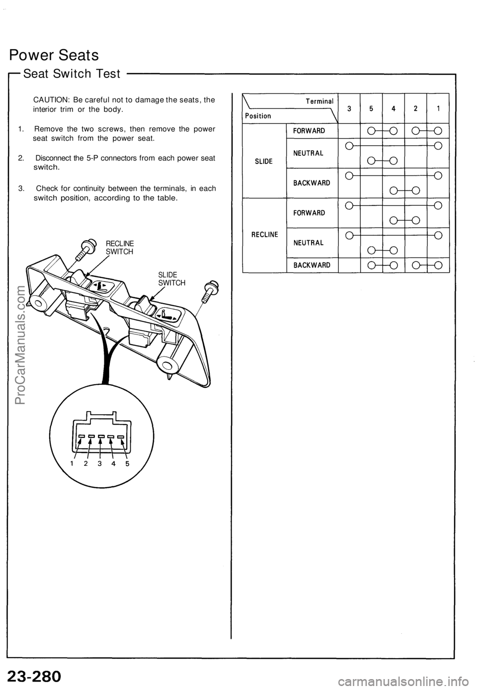
Power Seats
Seat Switch Test
CAUTION: Be careful not to damage the seats, the
interior trim or the body.
1. Remove the two screws, then remove the power
seat switch from the power seat.
2. Disconnect the 5-P connectors from each power seat
switch.
3. Check for continuity between the terminals, in each
switch position, according to the table.
RECLINE
SWITCH
SLIDE
SWITCHProCarManuals.com
Page 918 of 1640
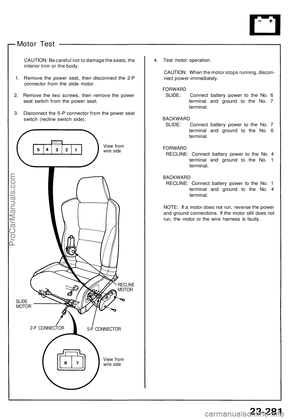
Motor Test
CAUTION: Be careful not to damage the seats, the
interior trim or the body.
1. Remove the power seat, then disconnect the 2-P
connector from the slide motor.
2. Remove the two screws, then remove the power
seat switch from the power seat.
3. Disconnect the 5-P connector from the power seat
switch (recline switch side).
View from
wire side
SLIDE
MOTOR
RECLINE
MOTOR
View from
wire side
4. Test motor operation.
CAUTION: When the motor stops running, discon-
nect power immediately.
FORWARD
SLIDE: Connect battery power to the No. 6
terminal and ground to the No. 7
terminal.
BACKWARD
SLIDE: Connect battery power to the No. 7
terminal and ground to the No. 6
terminal.
FORWARD
RECLINE: Connect battery power to the No. 4
terminal and ground to the No. 1
terminal.
BACKWARD
RECLINE: Connect battery power to the No. 1
terminal and ground to the No. 4
terminal.
NOTE: If a motor does not run, reverse the power
and ground connections. If the motor still does not
run, the motor or the wire harness is faulty.
5-P CONNECTOR
2-P CONNECTORProCarManuals.com
Page 1029 of 1640
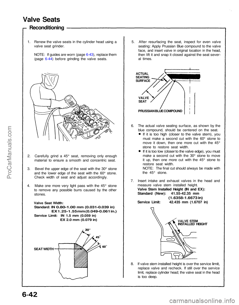
SEAT WIDTH
2. Carefully grind a 45° seat, removing only enough
material to ensure a smooth and concentric seat.
3. Bevel the upper edge of the seat with the 30° stone and the lower edge of the seat with the 60° stone.Check width of seat and adjust accordingly.
4. Make one more very light pass with the 45° stone to remove any possible burrs caused by the otherstones.
Valve Seat Width:
Standard:
IN
0.80-1.00
mm
(0.031-0.039
in)
EX 1.25-1.55 mm (0.049-0.061 in.)
Service Limit: IN 1.5 mm (0.059 in)
EX 2.0 mm (0.079 in)
1. Renew the valve seats in the cylinder head using a
valve seat grinder.
NOTE: If guides are worn (page 6-43), replace them(page 6-44) before grinding the valve seats.
Valve Seats
Reconditioning
5. After resurfacing the seat, inspect for even valveseating: Apply Prussian Blue compound to the valve
face, and insert valve in original location in the head,
then lift it and snap it closed against the seat sever-
al times.
ACTUAL
SEATING
SURFACE
VALVE
SEAT
PRUSSIAN BLUE COMPOUND
7. Insert intake and exhaust valves in the head and measure valve stem installed height.
Valve Stem Installed Height (IN and EX): Standard (New): 41.55-42.35 mm
(1.6358-1.6673 in)
Service Limit: 42.435 mm (1.6707 in)
VALVE STEM
INSTALLED HEIGHT
8. If
valve stem
installed
height
is
over
the
service
limit,
replace valve and recheck. If still over the service
limit, replace cylinder head; the valve seat in the head
is too deep.
6. The actual valve seating surface, as shown by the
blue compound, should be centered on the seat.
If it is too high (closer to the valve stem), you
must make a second cut with the 60° stone to
move it down, then one more cut with the 45°
stone to restore seat width.
If it is too low (closer to the valve edge), you must
make a second cut with the 30° stone to move
it up, then one more cut with the 45° stone to
restore seat width.
NOTE: The final cut should always be made with
the 45° stone.ProCarManuals.com