low beam ACURA NSX 1991 Service Repair Manual
[x] Cancel search | Manufacturer: ACURA, Model Year: 1991, Model line: NSX, Model: ACURA NSX 1991Pages: 1640, PDF Size: 60.48 MB
Page 79 of 1640
Engine Removal/Installatio n
Installation
Engine Installation :
Instal l th e engin e in th e revers e orde r o f removal . Reinstal l
th e moun t bolts/nut s i n th e followin g sequence , failur e t o
follo w thes e procedure s ma y caus e excessiv e nois e an d
vibration , an d reduc e bushin g life .
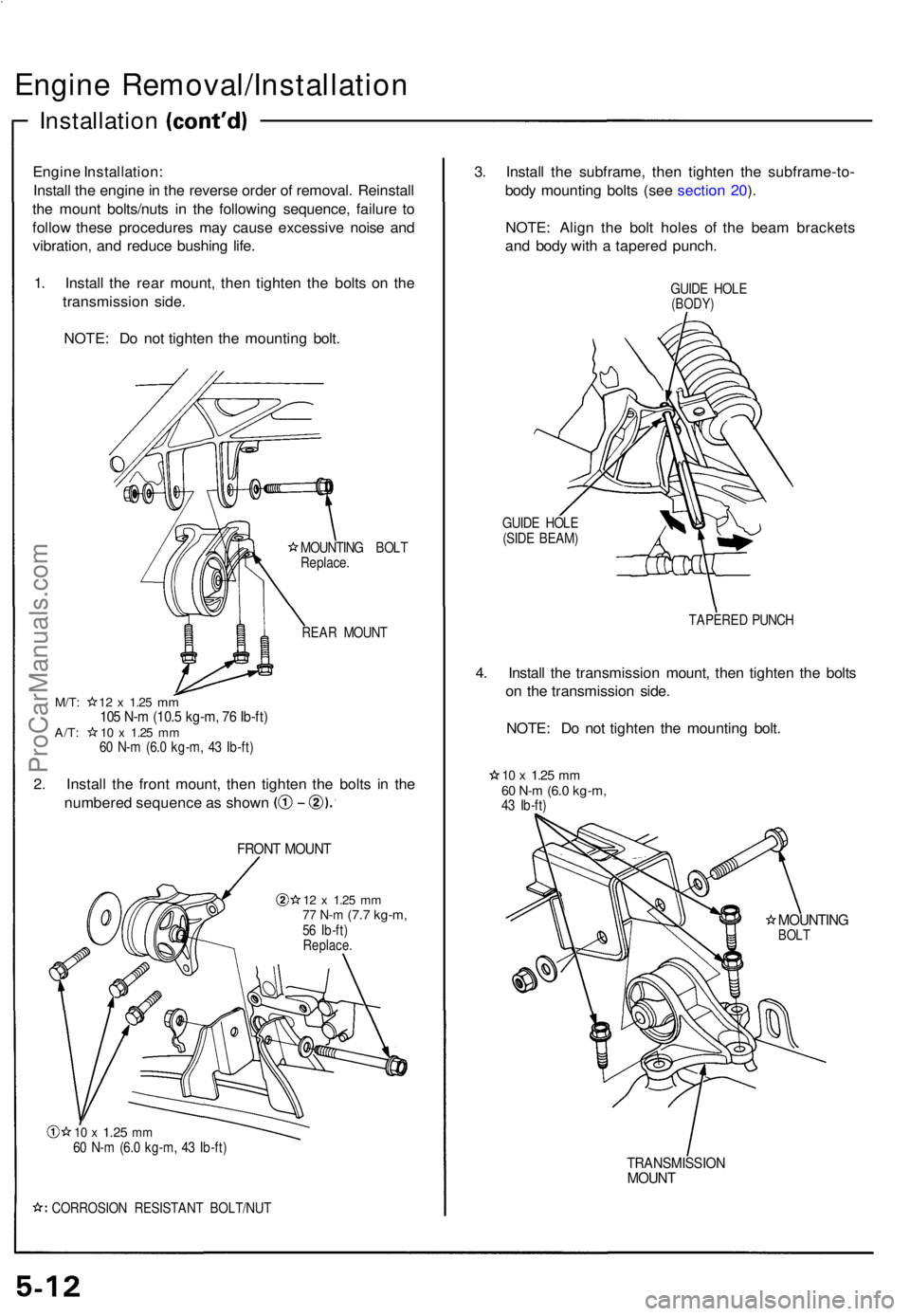
1 . Instal l th e rea r mount , the n tighte n th e bolt s o n th e
transmissio n side .
NOTE : D o no t tighte n th e mountin g bolt .
MOUNTIN G BOL T
Replace .
REA R MOUN T
M/T: 1 2 x 1.2 5 mm105 N- m (10. 5 kg-m , 7 6 Ib-ft )A/T: 1 0 x 1.2 5 mm60 N- m (6. 0 kg-m , 4 3 Ib-ft )
2. Instal l th e fron t mount , the n tighte n th e bolt s i n th e
numbere d sequenc e a s show n
FRONT MOUN T
12 x 1.2 5 mm77 N- m (7. 7 kg-m ,56 Ib-ft )Replace .
10 x 1.2 5 mm60 N- m (6. 0 kg-m , 4 3 Ib-ft )
CORROSIO N RESISTAN T BOLT/NU T
3. Instal l th e subframe , the n tighte n th e subframe-to -
bod y mountin g bolt s (se e sectio n 20 ).
NOTE : Alig n th e bol t hole s o f th e bea m bracket s
an d bod y wit h a tapere d punch .
GUIDE HOL E(BODY )
GUIDE HOL E
(SID E BEAM )
TAPERED PUNC H
4. Instal l th e transmissio n mount , the n tighte n th e bolt s
o n th e transmissio n side .
NOTE : D o no t tighte n th e mountin g bolt .
10 x 1.2 5 mm60 N- m (6. 0 kg-m ,43 Ib-ft )
MOUNTIN GBOLT
TRANSMISSIO NMOUNT
ProCarManuals.com
Page 121 of 1640
Cylinder Head s
Installatio n
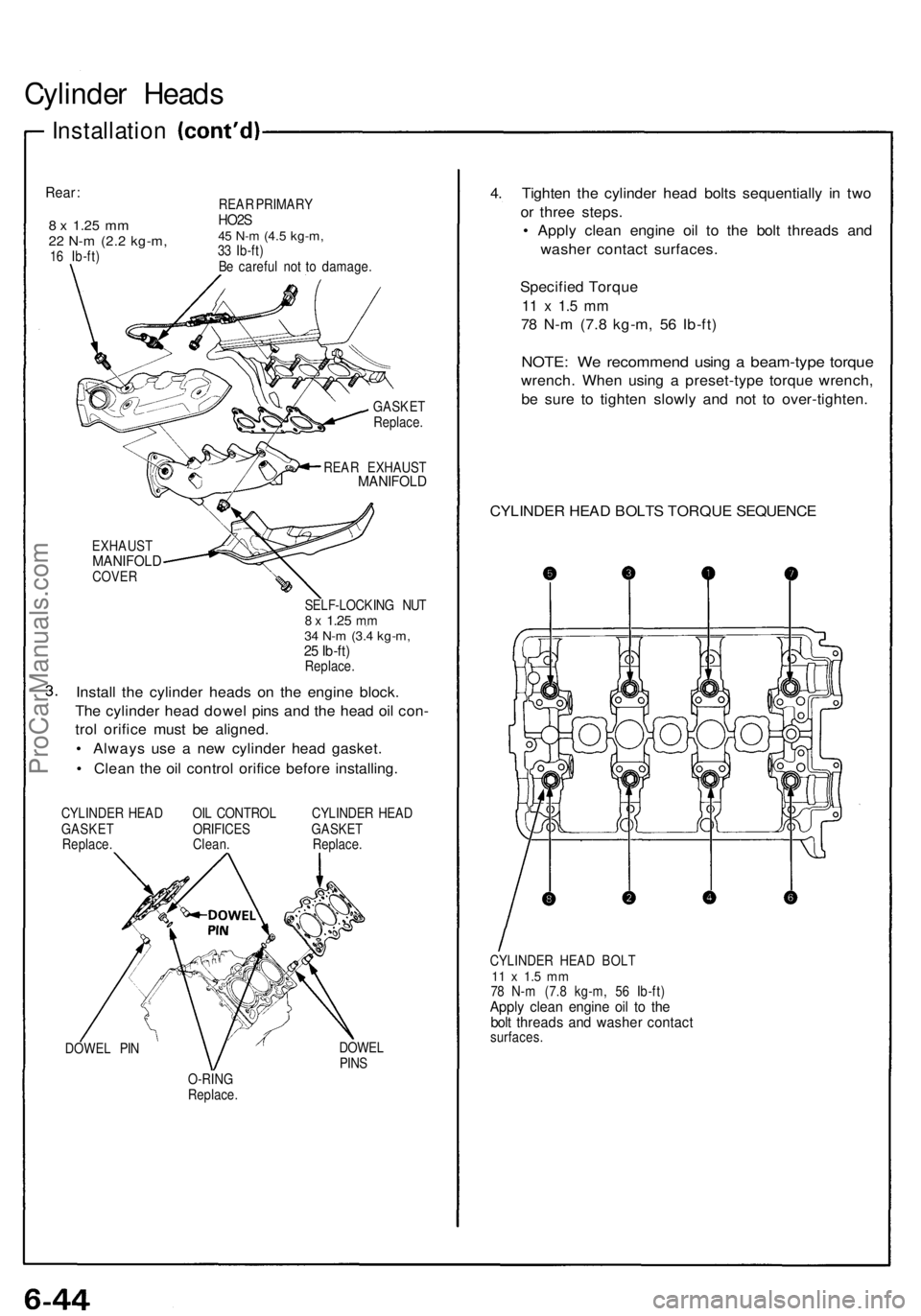
Rear:
8 x 1.2 5 mm22 N- m (2. 2 kg-m ,16 Ib-ft ) REA
R PRIMAR Y
HO2S45 N- m (4. 5 kg-m ,33 Ib-ft )
B e carefu l no t t o damage .
GASKE T
Replace .
REA R EXHAUS T
MANIFOLD
EXHAUSTMANIFOL DCOVER
SELF-LOCKIN G NU T8 x 1.2 5 mm34 N- m (3. 4 kg-m ,25 Ib-ft )Replace .
Install th e cylinde r head s o n th e engin e block .
Th e cylinde r hea d dowe l pin s an d th e hea d oi l con -
tro l orific e mus t b e aligned .
• Alway s us e a ne w cylinde r hea d gasket .
• Clea n th e oi l contro l orific e befor e installing .
CYLINDE R HEA D OI L CONTRO L CYLINDE R HEA D
GASKE T ORIFICE S GASKE T
Replace . Clean . Replace .
DOWE L PI N DOWE
L
PIN S
O-RIN G
Replace .
4. Tighte n th e cylinde r hea d bolt s sequentiall y i n tw o
o r thre e steps .
• Appl y clea n engin e oi l t o th e bol t thread s an d
washe r contac t surfaces .
Specifie d Torqu e
11 x 1. 5 m m
78 N- m (7. 8 kg-m , 5 6 Ib-ft )
NOTE : W e recommen d usin g a beam-typ e torqu e
wrench . Whe n usin g a preset-typ e torqu e wrench ,
b e sur e t o tighte n slowl y an d no t t o over-tighten .
CYLINDE R HEA D BOLT S TORQU E SEQUENC E
CYLINDER HEA D BOL T11 x 1. 5 m m78 N- m (7. 8 kg-m , 5 6 Ib-ft )Apply clea n engin e oi l t o th ebolt thread s an d washe r contac tsurfaces .
ProCarManuals.com
Page 306 of 1640
Transmission Assembly
Removal
20. Remove the intermediate shaft heat cover and the intermediate shaft mounting bolts.
21. Pry the intermediate shaft out of the differential. Pull and remove it. NOTE:
• Coat all precision finished surfaces with clean engine oil or grease.
• Tie plastic bags over the driveshaft ends.
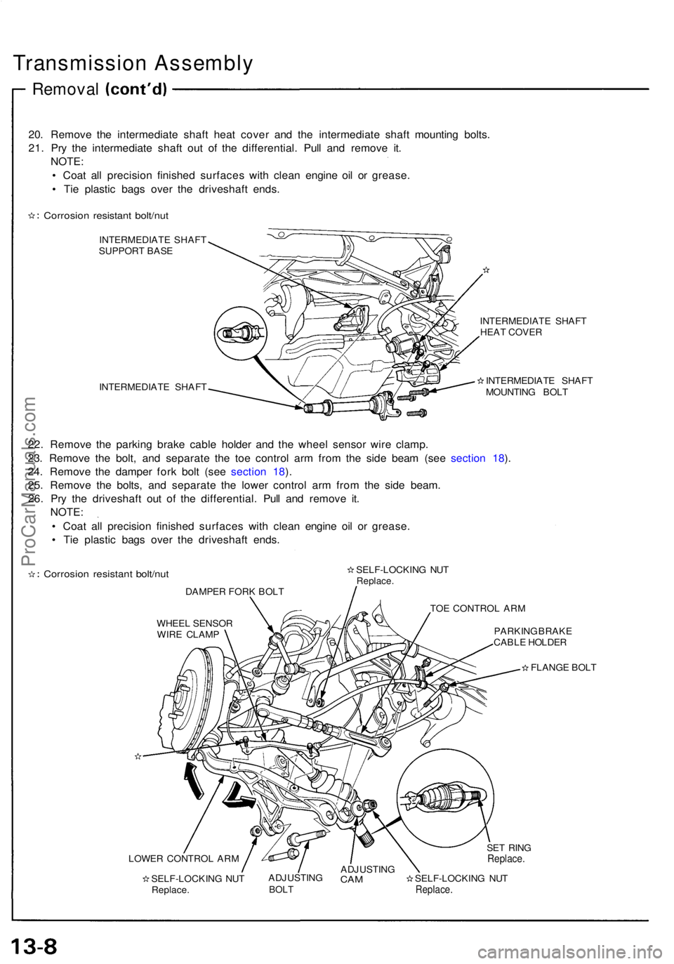
Corrosion resistant bolt/nut
INTERMEDIATE SHAFT
SUPPORT BASE
INTERMEDIATE SHAFT INTERMEDIATE SHAFT
HEAT COVER
INTERMEDIATE SHAFT
MOUNTING BOLT
22. Remove the parking brake cable holder and the wheel sensor wire clamp.
23. Remove the bolt, and separate the toe control arm from the side beam (see section 18).
24. Remove the damper fork bolt (see section 18).
25. Remove the bolts, and separate the lower control arm from the side beam. 26. Pry the driveshaft out of the differential. Pull and remove it. NOTE:
• Coat all precision finished surfaces with clean engine oil or grease.
• Tie plastic bags over the driveshaft ends.
Corrosion resistant bolt/nut
DAMPER FORK BOLT SELF-LOCKING NUT
Replace.
TOE CONTROL ARM
WHEEL SENSOR WIRE CLAMP PARKING BRAKE
CABLE HOLDER
FLANGE BOLT
LOWER CONTROL ARM SELF-LOCKING NUTReplace. ADJUSTING
BOLT
ADJUSTING
CAM
SELF-LOCKING NUT
Replace.
SET RING
Replace.ProCarManuals.com
Page 439 of 1640
NOTE: Before removing the gearbox, place a stand jack
under the gearbox and front crossbeam to lightly sup-
port them. Lower the gearbox together with the front
crossbeam.
18. Remove the flange bolts and nuts of the gearbox
and front crossbeam.
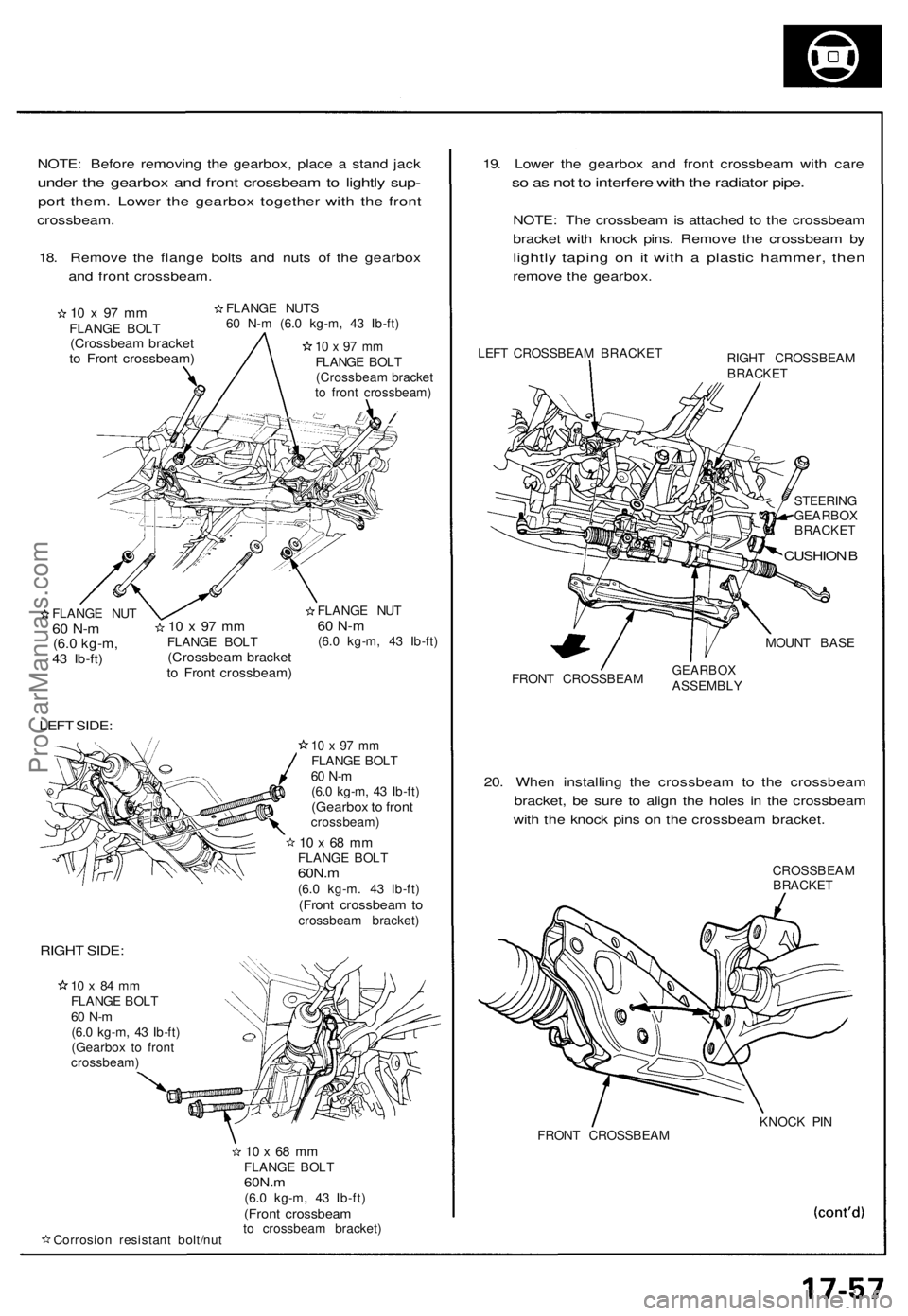
10 x 97 mm
FLANGE BOLT
(Crossbeam bracket
to Front crossbeam)
FLANGE NUTS
60 N-m (6.0 kg-m, 43 Ib-ft)
10 x 97 mm
FLANGE BOLT
(Crossbeam bracket
to front crossbeam)
/
FLANGE NUT
60 N-m
(6.0 kg-m,
43 Ib-ft)
LEFT SIDE:
10 x 97 mm
FLANGE BOLT
(Crossbeam bracket
to Front crossbeam)
FLANGE NUT
60 N-m
(6.0 kg-m, 43 Ib-ft)
10 x 97 mm
FLANGE BOLT
60 N-m
(6.0 kg-m, 43 Ib-ft)
(Gearbox to front
crossbeam)
10 x 68 mm
FLANGE BOLT
60N.m
(6.0 kg-m. 43 Ib-ft)
(Front crossbeam to
crossbeam bracket)
RIGHT SIDE:
10 x 84 mm
FLANGE BOLT
60 N-m
(6.0 kg-m, 43 Ib-ft)
(Gearbox to front
crossbeam)
Corrosion resistant bolt/nut
10 x 68 mm
FLANGE BOLT
60N.m
(6.0 kg-m, 43 Ib-ft)
(Front crossbeam
to crossbeam bracket)
19. Lower the gearbox and front crossbeam with care
so as not to interfere with the radiator pipe.
NOTE: The crossbeam is attached to the crossbeam
bracket with knock pins. Remove the crossbeam by
lightly taping on it with a plastic hammer, then
remove the gearbox.
LEFT CROSSBEAM BRACKET
RIGHT CROSSBEAM
BRACKET
STEERING
GEARBOX
BRACKET
CUSHION B
MOUNT BASE
FRONT CROSSBEAM
GEARBOX
ASSEMBLY
20. When installing the crossbeam to the crossbeam
bracket, be sure to align the holes in the crossbeam
with the knock pins on the crossbeam bracket.
CROSSBEAM
BRACKET
FRONT CROSSBEAM
KNOCK PINProCarManuals.com
Page 789 of 1640
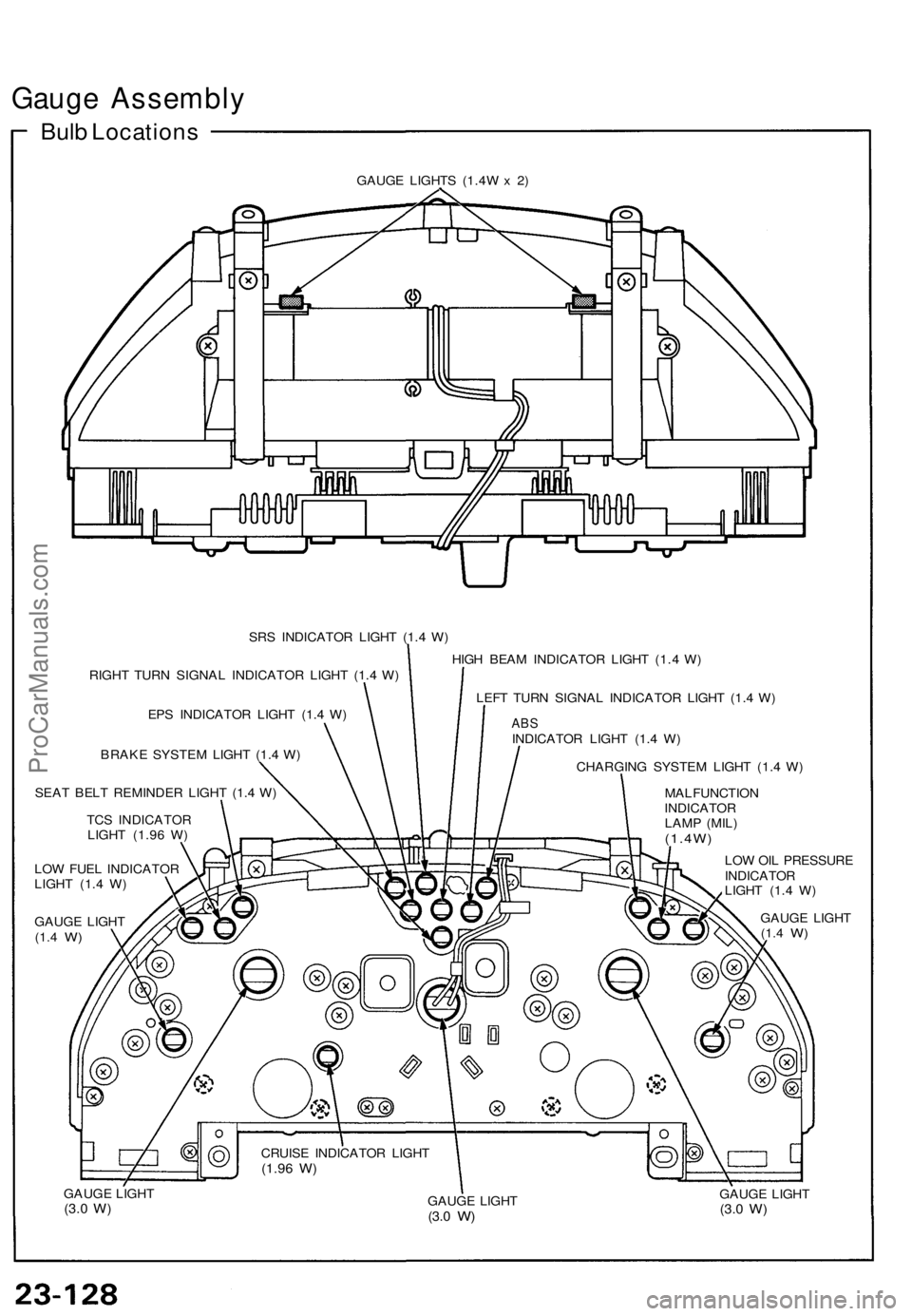
Gauge Assembly
Bulb Locations
GAUGE LIGHTS (1.4W x 2)
SRS INDICATOR LIGHT (1.4 W)
RIGHT TURN SIGNAL INDICATOR LIGHT (1.4 W)
EPS INDICATOR LIGHT (1.4 W)
BRAKE SYSTEM LIGHT (1.4 W)
SEAT BELT REMINDER LIGHT (1.4 W)
TCS INDICATOR
LIGHT (1.96 W)
LOW FUEL INDICATOR
LIGHT (1.4 W)
GAUGE LIGHT
(1.4
W)
HIGH BEAM INDICATOR LIGHT (1.4 W)
LEFT TURN SIGNAL INDICATOR LIGHT (1.4 W)
ABS
INDICATOR LIGHT (1.4 W)
CHARGING SYSTEM LIGHT (1.4 W)
MALFUNCTION
INDICATOR
LAMP (MIL)
(1.4W)
LOW OIL PRESSURE
INDICATOR
LIGHT (1.4 W)
GAUGE LIGHT
(1.4
W)
GAUGE LIGHT
(3.0
W)
GAUGE LIGHT
(3.0
W)
GAUGE LIGHT
(3.0
W)
CRUISE INDICATOR LIGHT
(1.96
W)ProCarManuals.com
Page 991 of 1640
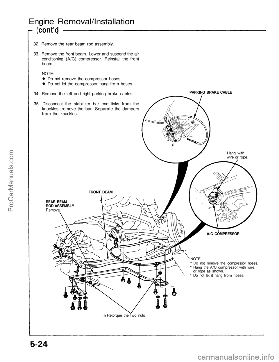
Engine Removal/Installation
(cont'd )
32. Remove the rear beam rod assembly.
33. Remove the front beam. Lower and suspend the air conditioning (A/C) compressor. Reinstall the frontbeam.
NOTE:
PARKING BRAKE CABLE
Hang with
wire or rope.
FRONT BEAM
REAR BEAM
ROD ASSEMBLY
Remove.
A/C COMPRESSOR
Do not remove the compressor hoses.
Hang the A/C compressor with wire
or rope as shown.
Do not let it hang from hoses.
Retorque the two nuts
NOTE:
Do not remove the compressor hoses.
Do not let the compressor hang from hoses.
34. Remove the left and right parking brake cables.
35. Disconnect the stabilizer bar end links from the knuckles, remove the bar. Separate the dampers
from the knuckles.ProCarManuals.com
Page 1036 of 1640
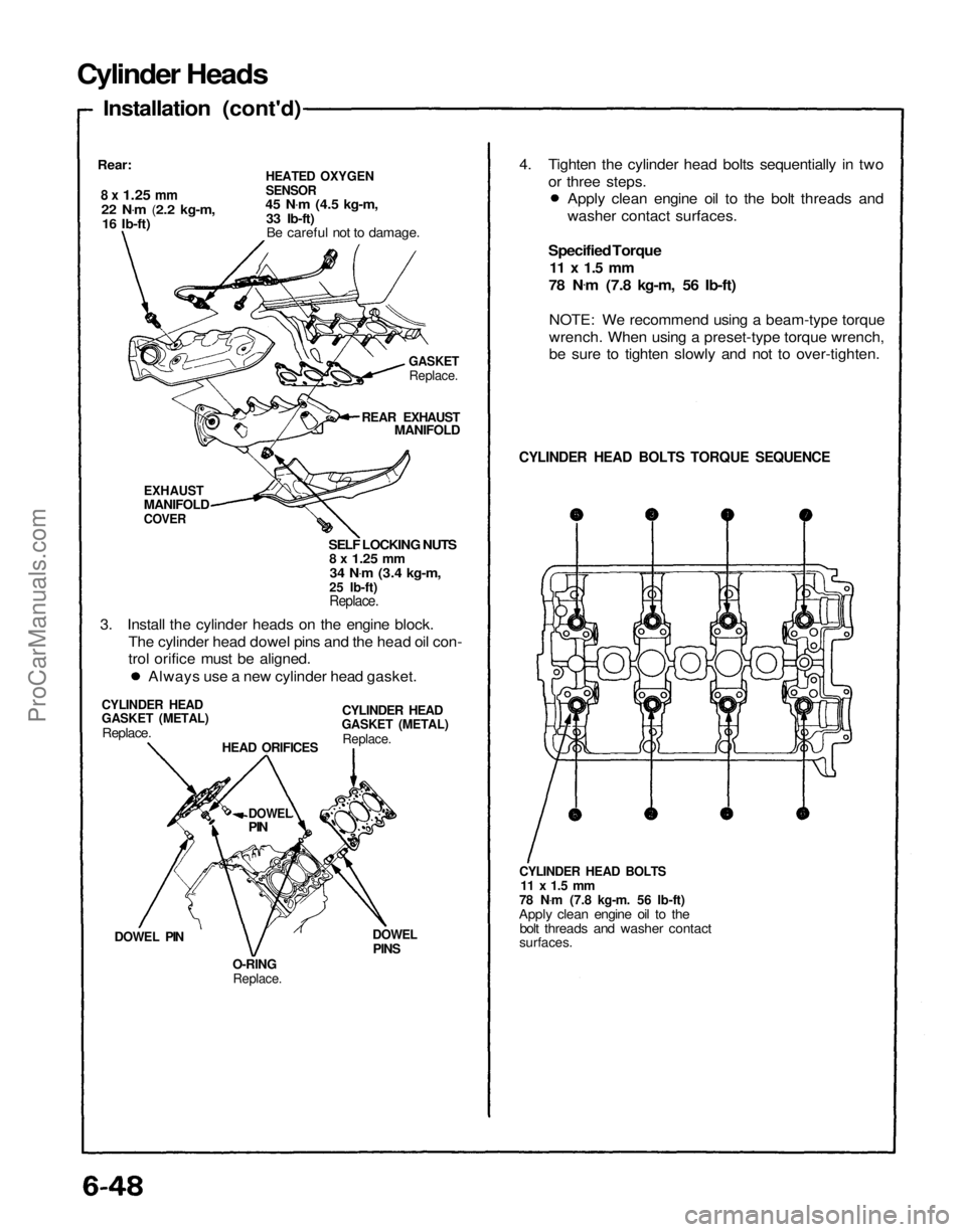
Cylinder Heads
Installation (cont'd)
Rear:
8 x
1.25
mm
22 N .
m
(2.2 kg-m,
16 Ib-ft)
HEATED OXYGEN
SENSOR
45 N .
m
(4.5 kg-m,
33 Ib-ft) Be careful not to damage.
GASKET
Replace.
REAR EXHAUST
MANIFOLD
EXHAUST
MANIFOLD
COVER
SELF LOCKING NUTS
8 x
1.25
mm
34 N .
m
(3.4 kg-m,
25 Ib-ft)
Replace.
3. Install the cylinder heads on the engine block. The cylinder head dowel pins and the head oil con-
trol orifice must be aligned.
CYLINDER HEAD
GASKET (METAL)
Replace.
CYLINDER HEAD
GASKET (METAL)
Replace.
HEAD ORIFICES
DOWEL
PIN
DOWEL PIN
O-RING
Replace.
DOWEL
PINS
CYLINDER HEAD BOLTS
11 x 1.5 mm
78 N .
m (7.8 kg-m. 56 Ib-ft)
Apply clean engine oil to the bolt threads and washer contact
surfaces.
CYLINDER HEAD BOLTS TORQUE SEQUENCE
Specified Torque
11 x 1.5 mm
78 N .
m (7.8 kg-m, 56 Ib-ft)
NOTE: We recommend using a beam-type torque
wrench. When using a preset-type torque wrench,
be sure to tighten slowly and not to over-tighten.
Always use a new cylinder head gasket. Apply clean engine oil to the bolt threads and
washer contact surfaces.
4. Tighten the cylinder head bolts sequentially in two
or three steps.ProCarManuals.com
Page 1149 of 1640
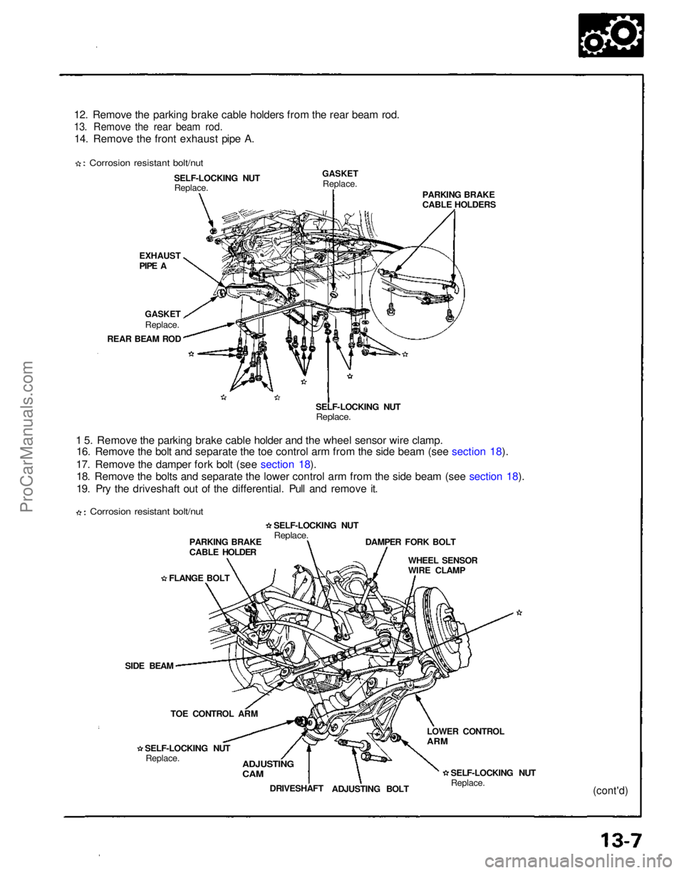
12. Remove the parking brake cable holders from the rear beam rod.
13. Remove the rear beam rod.
14. Remove the front exhaust pipe A.
Corrosion resistant bolt/nut
EXHAUST
PIPE ASELF-LOCKING NUT
Replace.
GASKET
Replace.
GASKET
Replace.
REAR BEAM ROD
1 5. Remove the parking brake cable holder and the wheel sensor wire clamp. 16. Remove the bolt and separate the toe control arm from the side beam (see section 18).
17. Remove the damper fork bolt (see section 18). 18. Remove the bolts and separate the lower control arm from the side beam (see section 18).
19. Pry the driveshaft out of the differential. Pull and remove it. SELF-LOCKING NUT
Replace.
PARKING BRAKE
CABLE HOLDERS
PARKING BRAKE
CABLE HOLDER
FLANGE BOLT
SIDE BEAM TOE CONTROL ARM
SELF-LOCKING NUT Replace. SELF-LOCKING NUT
Replace.
WHEEL SENSOR
WIRE CLAMP
DAMPER FORK BOLT
ADJUSTING
CAM
DRIVESHAFT
ADJUSTING BOLT SELF-LOCKING NUT
Replace.
LOWER CONTROL
ARM
(cont'd)
Corrosion resistant bolt/nutProCarManuals.com
Page 1150 of 1640
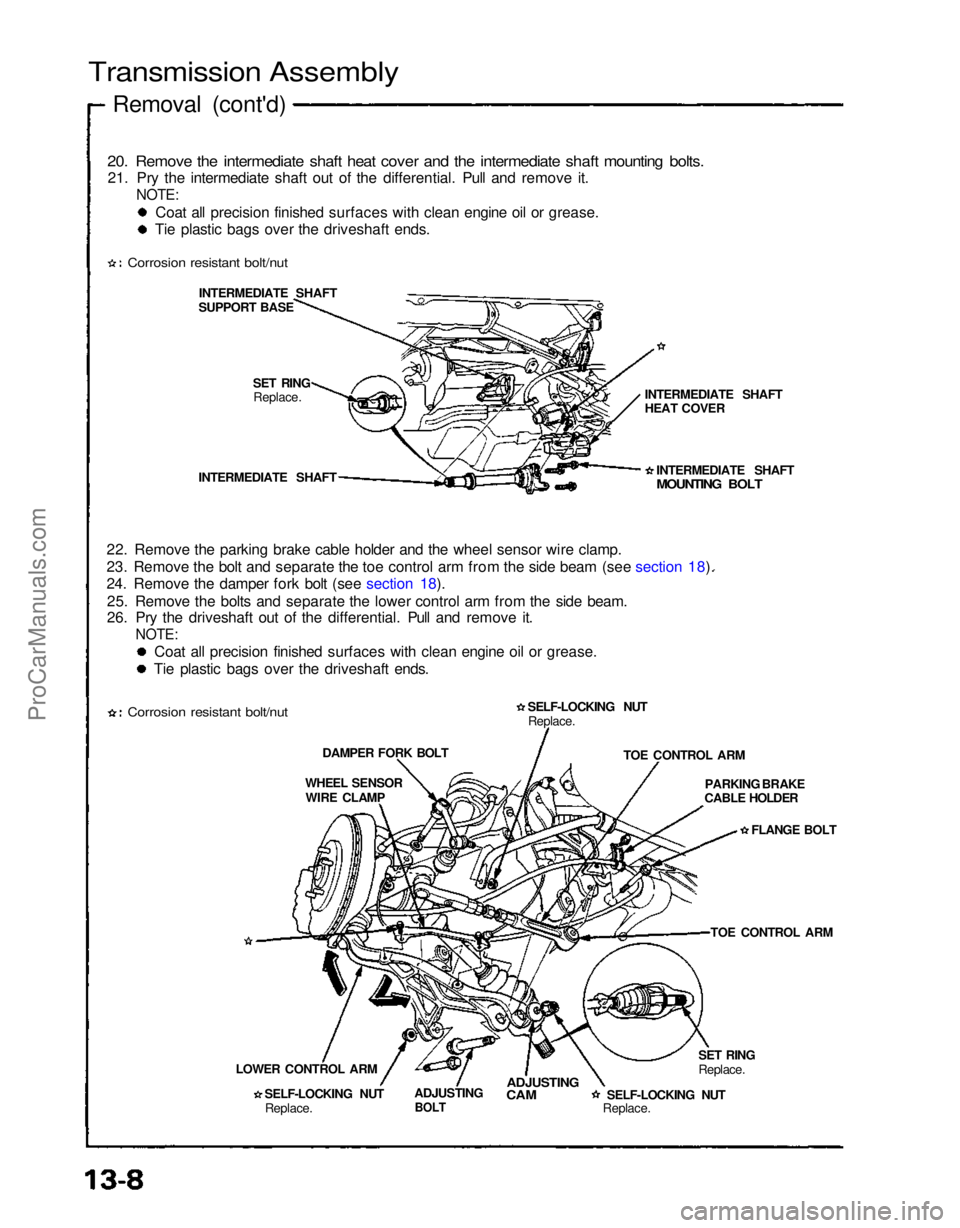
Transmission Assembly
Removal (cont'd)
20. Remove the intermediate shaft heat cover and the intermediate shaft mounting bolts.
21. Pry the intermediate shaft out of the differential. Pull and remove it.
NOTE:
Coat all precision finished surfaces with clean engine oil or grease.
Tie plastic bags over the driveshaft ends.
Corrosion resistant bolt/nut
INTERMEDIATE SHAFT
SUPPORT BASE
SET RINGReplace.
INTERMEDIATE SHAFT
22. Remove the parking brake cable holder and the wheel sensor wire clamp.
23. Remove the bolt and separate the toe control arm from the side beam (see section 18).
24. Remove the damper fork bolt (see section 18). 25. Remove the bolts and separate the lower control arm from the side beam.
26. Pry the driveshaft out of the differential. Pull and remove it.
NOTE:
Coat all precision finished surfaces with clean engine oil or grease.
Tie plastic bags over the driveshaft ends.
Corrosion resistant bolt/nut
DAMPER FORK BOLT
WHEEL SENSOR WIRE CLAMP
LOWER CONTROL ARM SELF-LOCKING NUTReplace. ADJUSTING
BOLT
ADJUSTING
CAM
SELF-LOCKING NUT
Replace.SET RING
Replace.TOE CONTROL ARM
PARKING BRAKE
CABLE HOLDER
FLANGE BOLT
TOE CONTROL ARM
SELF-LOCKING NUT
Replace. INTERMEDIATE SHAFT
MOUNTING BOLT
INTERMEDIATE SHAFT
HEAT COVERProCarManuals.com
Page 1161 of 1640
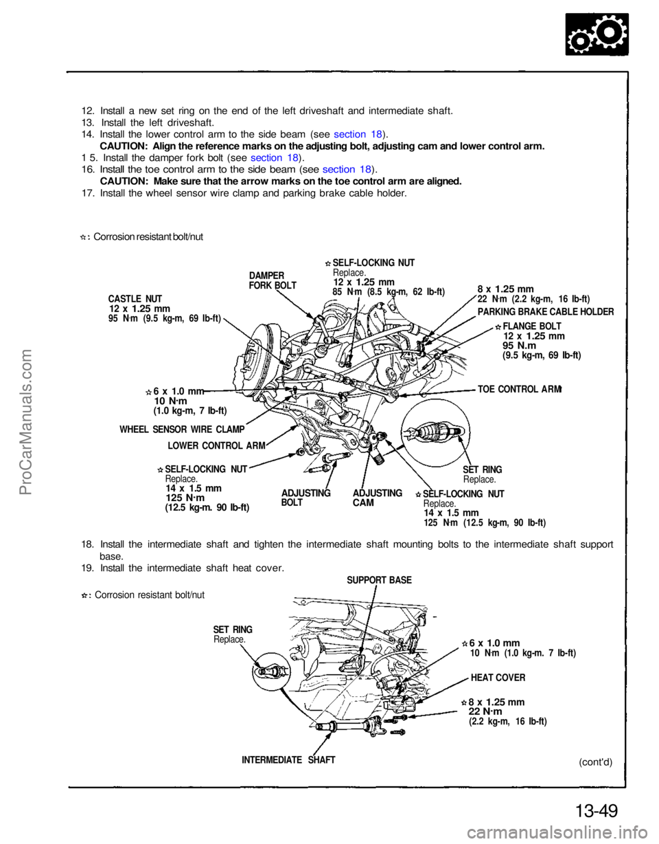
12. Install a new set ring on the end of the left driveshaft and intermediate shaft.
13. Install the left driveshaft.
14. Install the lower control arm to the side beam (see section 18).
CAUTION: Align the reference marks on the adjusting bolt, adjusting cam and lower control arm.
1 5. Install the damper fork bolt (see section 18).
16. Install the toe control arm to the side beam (see section 18).
CAUTION: Make sure that the arrow marks on the toe control arm are aligned.
17. Install the wheel sensor wire clamp and parking brake cable holder.
Corrosion resistant bolt/nut
CASTLE NUT
12 x
1.25
mm
95 N .
m (9.5 kg-m, 69 Ib-ft) DAMPER
FORK BOLT
6 x 1.0 mm
10 N .
m
(1.0 kg-m, 7 Ib-ft)
WHEEL SENSOR WIRE CLAMP LOWER CONTROL ARM
SELF-LOCKING NUT
Replace.
14 x 1.5 mm
125 N .
m
(12.5 kg-m. 90 Ib-ft)
ADJUSTING
BOLT
ADJUSTING
CAM
18. Install the intermediate shaft and tighten the intermediate shaft mounting bolts to the intermediate shaft support
base.
19. Install the intermediate shaft heat cover.
Corrosion resistant bolt/nut
SET RINGReplace.
13-49(cont'd)
INTERMEDIATE SHAFT
8 x
1.25
mm
22 N
.
m
(2.2 kg-m, 16 Ib-ft) HEAT COVER
6 x 1.0 mm
10 N .
m (1.0 kg-m. 7 Ib-ft)
SUPPORT BASE SELF-LOCKING NUT
Replace.
14 x 1.5 mm
125 N .
m (12.5 kg-m, 90 Ib-ft) SET RING
Replace. TOE CONTROL ARM
FLANGE BOLT
12 x
1.25
mm
95 N.m
(9.5 kg-m, 69 Ib-ft)
8 x
1.25
mm
22 N
.
m (2.2 kg-m, 16 Ib-ft)
PARKING BRAKE CABLE HOLDER
SELF-LOCKING NUT
Replace.
12 x
1.25
mm
85 N .
m (8.5 kg-m, 62 Ib-ft)ProCarManuals.com