tow ACURA NSX 1991 Service Repair Manual
[x] Cancel search | Manufacturer: ACURA, Model Year: 1991, Model line: NSX, Model: ACURA NSX 1991Pages: 1640, PDF Size: 60.48 MB
Page 11 of 1640
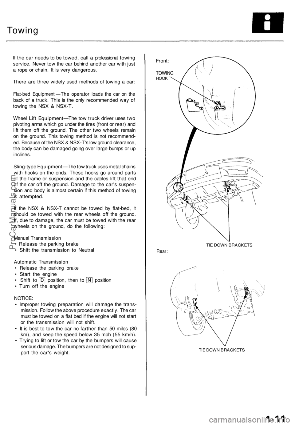
Towing
If th e ca r need s t o b e towed , cal l a professiona l towin g
service . Neve r to w th e ca r behin d anothe r ca r wit h jus t
a rop e o r chain . I t i s ver y dangerous .
Ther e ar e thre e widel y use d method s o f towin g a car :
Flat-be d Equipmen t — Th e operato r load s th e ca r o n th e
bac k o f a truck . Thi s i s th e onl y recommende d wa y o f
towin g th e NS X & NSX-T .
Whee l Lif t Equipment— The to w truc k drive r use s tw o
pivotin g arm s whic h g o unde r th e tire s (fron t o r rear ) an d
lif t the m of f th e ground . Th e othe r tw o wheel s remai n
o n th e ground . Thi s towin g metho d i s no t recommend -
ed . Becaus e o f th e NS X & NSX-T' s lo w groun d clearance ,
th e bod y ca n b e damage d goin g ove r larg e bump s o r u p
inclines .
Sling-typ e Equipment— The tow truc k use s meta l chain s
wit h hook s o n th e ends . Thes e hook s g o aroun d part s
of th e fram e or suspensio n and th e cable s lift tha t end
of th e ca r of f th e ground . Damag e t o th e car' s suspen -
sio n an d bod y i s almos t certai n if thi s metho d o f towin g
i s attempted .
I f th e NS X & NSX- T canno t b e towe d b y flat-bed , i t
shoul d b e towe d wit h th e rea r wheel s of f th e ground .
If , du e t o damage , th e ca r mus t b e towe d wit h th e rea r
wheel s o n th e ground , d o th e following :
Manual Transmissio n
• Releas e th e parkin g brak e
• Shif t th e transmissio n t o Neutra l
Automati c Transmissio n
• Releas e th e parkin g brak e
• Star t th e engin e
• Shif t t o position , the n t o positio n
• Tur n of f th e engin e
NOTICE :
• Imprope r towin g preparatio n wil l damag e th e trans -
mission . Follo w th e abov e procedur e exactly . Th e ca r
mus t b e towe d o n a fla t be d if th e engin e wil l no t star t
o r th e transmissio n wil l no t shift .
• I t i s bes t t o to w th e ca r n o farthe r tha n 5 0 mile s (8 0
km) , an d kee p th e spee d belo w 3 5 mp h (5 5 km/h) .
• Tryin g t o lif t o r to w th e ca r b y th e bumper s wil l caus e
seriou s damage . Th e bumper s ar e no t designe d to sup -
por t th e car' s weight .
Front:
TOWIN GHOOK
TIE DOW N BRACKET S
Rear:
TIE DOW N BRACKET S
ProCarManuals.com
Page 32 of 1640
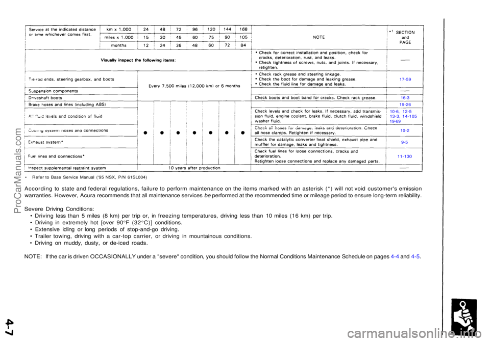
• Refe r t o Bas e Servic e Manua l ('9 5 NSX , P/ N 61SL004 )
According t o stat e an d federa l regulations , failur e t o perfor m maintenanc e o n th e item s marke d wit h a n asteris k (* ) wil l no t voi d customer' s emissio n
warranties . However , Acur a recommend s tha t al l maintenanc e service s be performe d a t th e recommende d tim e o r mileag e perio d to ensur e long-ter m reliability .
Severe Drivin g Conditions :
• Drivin g les s tha n 5 mile s ( 8 km ) pe r tri p or , i n freezin g temperatures , drivin g les s tha n 1 0 mile s (1 6 km ) pe r trip .
• Drivin g i n extremel y ho t [ove r 90° F (32°C) ] conditions .
• Extensiv e idlin g o r lon g period s o f stop-and-g o driving .
• Traile r towing , drivin g wit h a car-to p carrier , o r drivin g i n mountainou s conditions .
• Drivin g o n muddy , dusty , o r de-ice d roads .
NOTE : I f th e ca r i s drive n OCCASIONALL Y unde r a "severe " condition , yo u shoul d follo w th e Norma l Condition s Maintenanc e Schedul e o n page s 4- 4 an d 4-5 .
17-5 9
16-3
19-2 6
10-6 , 12- 5
13-3, 14-10 519-69
10-2
9-5
11-13 0
ProCarManuals.com
Page 44 of 1640
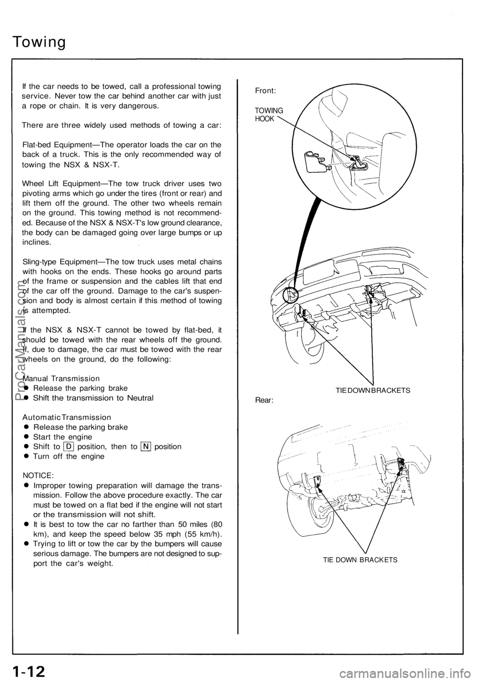
Towing
If th e ca r need s t o b e towed , cal l a professiona l towin g
service . Neve r to w th e ca r behin d anothe r ca r wit h jus t
a rop e o r chain . I t i s ver y dangerous .
Ther e ar e thre e widel y use d method s o f towin g a car :
Flat-be d Equipment—Th e operato r load s th e ca r o n th e
bac k o f a truck . This is th e onl y recommende d wa y o f
towin g th e NS X & NSX-T .
Whee l Lif t Equipment—Th e to w truc k drive r use s tw o
pivotin g arm s whic h g o unde r th e tire s (fron t o r rear ) an d
lif t the m of f th e ground . Th e othe r tw o wheel s remai n
o n th e ground . Thi s towin g metho d i s no t recommend -
ed . Becaus e o f th e NS X & NSX-T' s lo w groun d clearance ,
th e bod y ca n b e damage d goin g ove r larg e bump s o r u p
inclines .
Sling-typ e Equipment—Th e to w truc k use s meta l chain s
wit h hooks on th e ends . Thes e hook s g o aroun d part s
o f th e fram e o r suspensio n an d th e cable s lif t tha t en d
o f th e ca r of f th e ground . Damag e t o th e car' s suspen -
sio n an d bod y i s almos t certai n if thi s metho d o f towin g
i s attempted .
I f th e NS X & NSX- T canno t b e towe d b y flat-bed , i t
shoul d b e towe d wit h th e rea r wheel s of f th e ground .
If , du e t o damage , th e ca r mus t b e towe d wit h th e rea r
wheel s o n th e ground , d o th e following :
Manual Transmissio n
Release th e parkin g brak e
Shift th e transmissio n t o Neutra l
Automati c Transmissio n
Releas e th e parkin g brak e
Star t th e engin e
Shift t o position , the n t o positio n
Tur n of f th e engin e
NOTICE :
Improper towin g preparatio n wil l damag e th e trans -
mission . Follo w th e abov e procedur e exactly . Th e ca r
mus t b e towe d o n a fla t be d if th e engin e wil l no t star t
or th e transmissio n wil l no t shift .
It i s bes t t o to w th e ca r n o farthe r tha n 5 0 mile s (8 0
km) , an d kee p th e spee d belo w 3 5 mp h (5 5 km/h) .
Tryin g t o lif t o r to w th e ca r b y th e bumper s wil l caus e
seriou s damage . Th e bumper s ar e no t designe d to sup -
por t th e car' s weight .
Front:
TOWIN GHOOK
TIE DOW N BRACKET S
Rear:
TIE DOW N BRACKET S
ProCarManuals.com
Page 68 of 1640
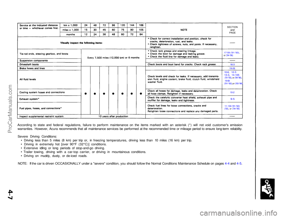
SECTION
and
PAGE
17-59 ('91-'93),
or ('94-'96)
16-3
19-26
10-6, 12-5
13-3, 14-105
('91-'93), or ('94-'96), 19-69
('91-'92),or ('93-'96)
10-2
9-5
11-130 ('91-'92)('93), or ('94-'96)
According to state and federal regulations, failure to perform maintenance on the items marked with an asterisk (*) will not void customer's emission
warranties. However, Acura recommends that all maintenance services be performed at the recommended time or mileage period to ensure long-term reliability.
Severe Driving Conditions: Driving less than 5 miles (8 km) per trip or, in freezing temperatures, driving less than 10 miles (16 km) per trip.
Driving in extremely hot [over 90°F (32°C)] conditions.
Extensive idling or long periods of stop-and-go driving.
Trailer towing, driving with a car-top carrier, or driving in mountainous conditions.
Driving on muddy, dusty, or de-iced roads.
NOTE: If the car is driven OCCASIONALLY under a "severe" condition, you should follow the Normal Conditions Maintenance Schedule on pages 4-4 and 4-5.ProCarManuals.com
Page 83 of 1640
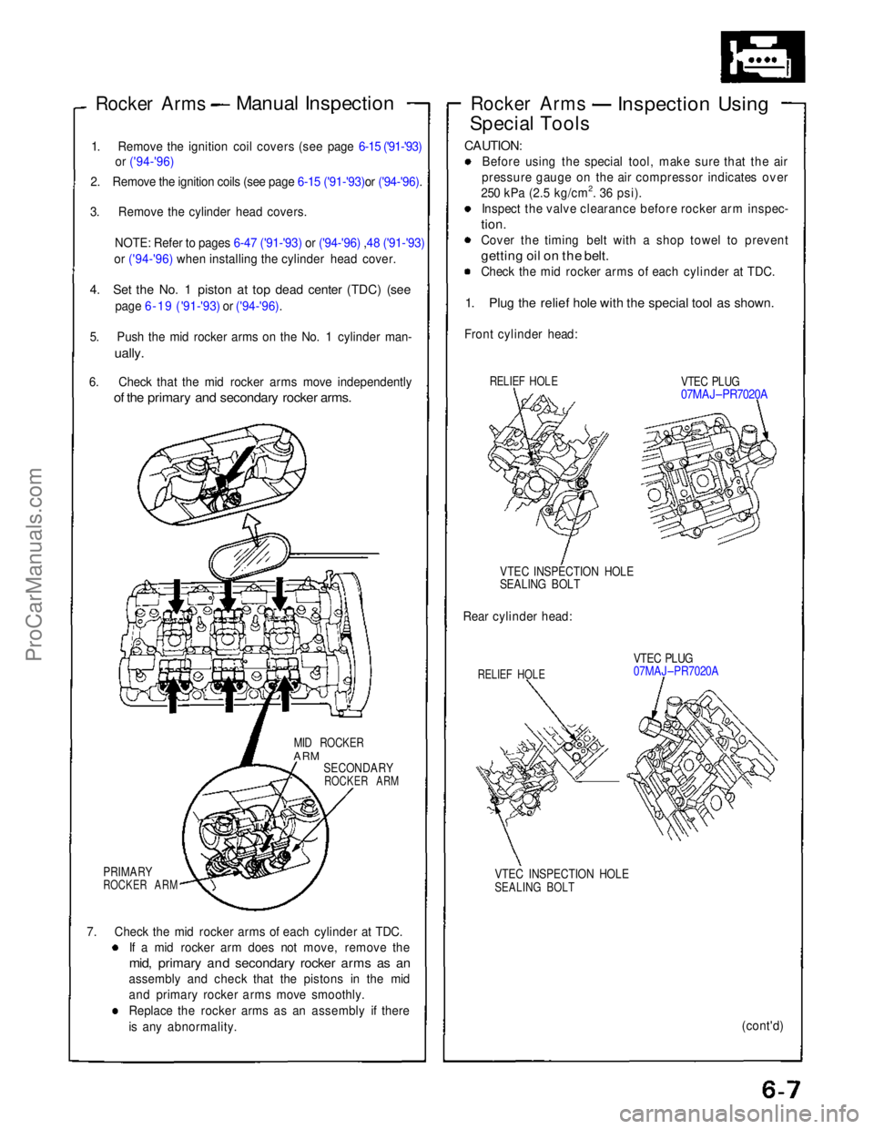
Rocker Arms
Manual Inspection
1. Remove the ignition coil covers (see page 6-15 ('91-'93) or ('94-'96)
2. Remove the ignition coils (see page 6-15 ('91-'93)or ('94-'96).
3. Remove the cylinder head covers.
NOTE: Refer to pages 6-47 ('91-'93)
or ('94-'96) ,48 ('91-'93)
or ('94-'96) when installing the cylinder head cover.
4. Set the No. 1 piston at top dead center (TDC) (see
page 6-19 ('91-'93)
or ('94-'96).
5. Push the mid rocker arms on the No. 1 cylinder man-
ually.
6. Check that the mid rocker arms move independently
of the primary and secondary rocker arms.
MID ROCKER
ARM
SECONDARY
ROCKER ARM
PRIMARY
ROCKER ARM
7. Check the mid rocker arms of each cylinder at TDC. If a mid rocker arm does not move, remove the
mid, primary and secondary rocker arms as an
assembly and check that the pistons in the mid
and primary rocker arms move smoothly.
Replace the rocker arms as an assembly if there
is any abnormality. Rocker Arms
Inspection Using
Special Tools
CAUTION:
Before using the special tool, make sure that the air
pressure gauge on the air compressor indicates over
250 kPa (2.5 kg/cm2. 36 psi). Inspect the valve clearance before rocker arm inspec-
tion.
Cover the timing belt with a shop towel to prevent
getting oil on the belt.
Check the mid rocker arms of each cylinder at TDC.
1. Plug the relief hole with the special tool as shown.
Front cylinder head:
RELIEF HOLE
VTEC PLUG
07MAJ–PR7020A
VTEC INSPECTION HOLE
SEALING BOLT
Rear cylinder head:
RELIEF HOLE
VTEC PLUG
07MAJ–PR7020A
VTEC INSPECTION HOLE
SEALING BOLT
(cont'd)ProCarManuals.com
Page 100 of 1640
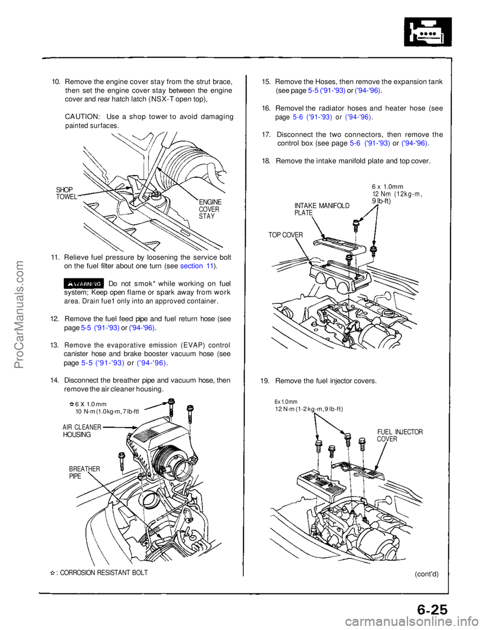
10. Remove the engine cover stay from the strut brace,
then set the engine cover stay between the engine
cover and rear hatch latch (NSX-T open top),
CAUTION: Use a shop tower to avoid damaging
painted surfaces.
SHOP
TOWEL
11. Relieve fuel pressure by loosening the service bolt on the fuel filter about one turn (see section 11).
Do not smok* while working on fuel
system; Keep open flame or spark away from work
area. Drain fue1 only into an approved container.
12. Remove the fuel feed pipe and fuel return hose (see page 5-5 ('91-'93) or ('94-'96).
13. Remove the evaporative emission (EVAP) control
canister hose and brake booster vacuum hose (see
page 5-5 ('91-'93) or ('94-'96).
14. Disconnect the breather pipe and vacuum hose, then remove the air cleaner housing.
6 x 1.0 mm
10 N·m (1.0 kg-m, 7 lb-ftl
AIR CLEANER
HOUSING
BREATHER
PIPE
: CORROSION RESISTANT BOLT
15. Remove the Hoses, then remove the expansion tank
(see page 5-5 ('91-'93) or ('94-'96).
16. Removel the radiator hoses and heater hose (see
page 5-6 ('91-'93) or ('94-'96).
17. Disconnect the two connectors, then remove the
control box (see page 5-6 ('91-'93) or ('94-'96).
18. Remove the intake manifold plate and top cover.
INTAKE MANIFOLD
PLATE
6 x
1.0mm
12 N·m (12kg-m,
9 lb-ft)
TOP COVER
19. Remove the fuel injector covers.
6 x 1.0 mm
12 N·m (1-2 kg-m, 9 lb-ft)
FUEL INJECTOR
COVER
(cont'd)
ENGINE
COVER
STAYProCarManuals.com
Page 105 of 1640
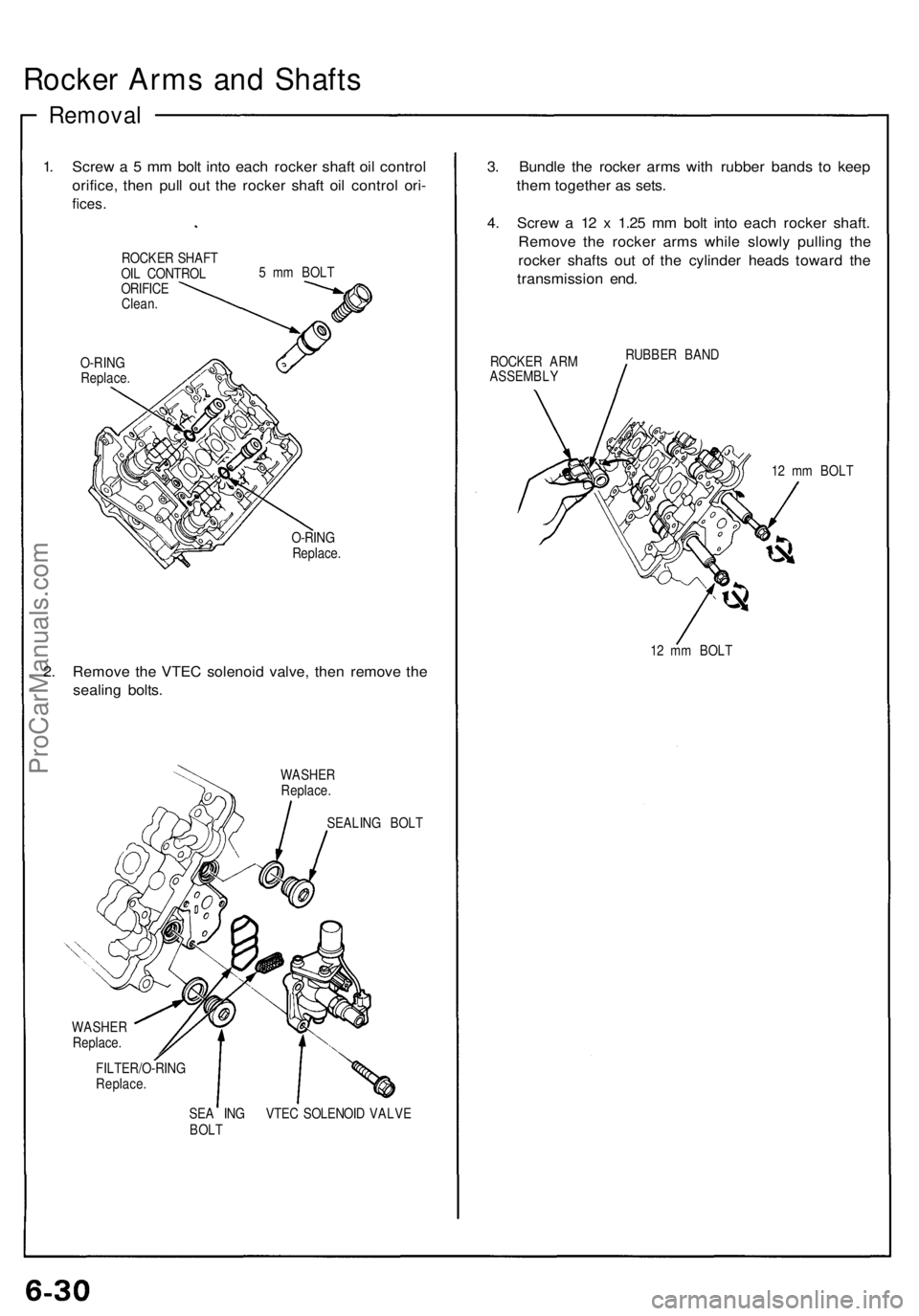
Rocker Arm s an d Shaft s
Remova l
1. Scre w a 5 m m bol t int o eac h rocke r shaf t oi l contro l
orifice , the n pul l ou t th e rocke r shaf t oi l contro l ori -
fices .
ROCKE R SHAF T
OI L CONTRO L
ORIFIC E
Clean . 5
m m BOL T
O-RIN G
Replace .
O-RING
Replace .
2. Remov e th e VTE C solenoi d valve , the n remov e th e
sealin g bolts .
WASHE R
Replace .
SEALIN G BOL T
WASHE R
Replace .
FILTER/O-RIN G
Replace .
SEA IN G VTE C SOLENOI D VALV E
BOL T
3. Bundl e th e rocke r arm s wit h rubbe r band s t o kee p
the m togethe r a s sets .
4 . Scre w a 1 2 x 1.2 5 m m bol t int o eac h rocke r shaft .
Remov e th e rocke r arm s whil e slowl y pullin g th e
rocke r shaft s ou t o f th e cylinde r head s towar d th e
transmissio n end .
ROCKE R AR M
ASSEMBL Y RUBBE
R BAN D
12 m m BOL T
1 2 m m BOL T
ProCarManuals.com
Page 109 of 1640
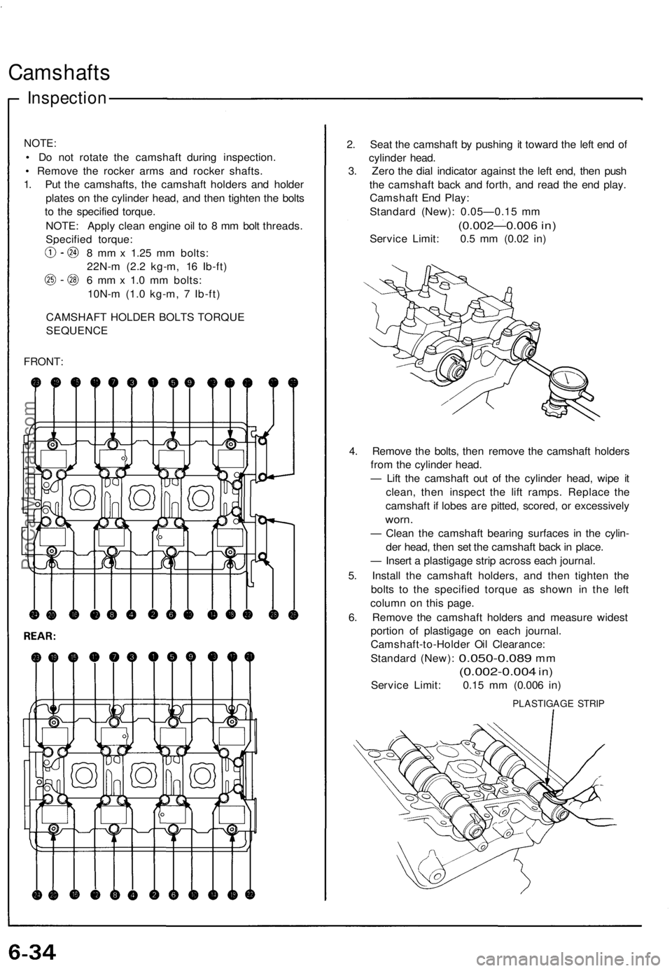
Camshafts
Inspection
NOTE:
• D o no t rotat e th e camshaf t durin g inspection .
• Remov e th e rocke r arm s an d rocke r shafts .
1 . Pu t th e camshafts , th e camshaf t holder s an d holde r
plate s o n th e cylinde r head , an d the n tighte n th e bolt s
t o th e specifie d torque .
NOTE : Appl y clea n engin e oi l t o 8 m m bol t threads .
Specifie d torque :
8 m m x 1.2 5 m m bolts :
22N- m (2. 2 kg-m , 1 6 Ib-ft )
6 m m x 1. 0 m m bolts :
10N- m (1. 0 kg-m , 7 Ib-ft )
CAMSHAF T HOLDE R BOLT S TORQU E
SEQUENCE
FRONT :
2. Sea t th e camshaf t b y pushin g i t towar d th e lef t en d o f
cylinde r head .
3 . Zer o th e dia l indicato r agains t th e lef t end , the n pus h
th e camshaf t bac k an d forth , an d rea d th e en d play .
Camshaf t En d Play :
Standar d (New) : 0.05—0.1 5 m m
(0.002—0.006 in)
Servic e Limit : 0. 5 m m (0.0 2 in )
4 . Remov e th e bolts , the n remov e th e camshaf t holder s
fro m th e cylinde r head .
— Lif t th e camshaft out o f th e cylinde r head , wip e i t
clean , the n inspec t th e lif t ramps . Replac e th e
camshaft if lobe s ar e pitted , scored , o r excessivel y
worn.
— Clea n th e camshaf t bearin g surface s i n th e cylin -
de r head , the n se t th e camshaf t bac k in place .
— Inser t a plastigag e stri p acros s eac h journal.
5 . Instal l th e camshaf t holders , an d the n tighte n th e
bolt s t o th e specifie d torqu e a s show n i n th e lef t
colum n o n thi s page .
6 . Remov e th e camshaf t holder s an d measur e wides t
portio n o f plastigag e o n eac h journal .
Camshaft-to-Holde r Oi l Clearance :
Standar d (New) :
0.050-0.08 9 mm
(0.002-0.00 4 in)
Servic e Limit : 0.1 5 m m (0.00 6 in )
PLASTIGAG E STRI P
ProCarManuals.com
Page 116 of 1640
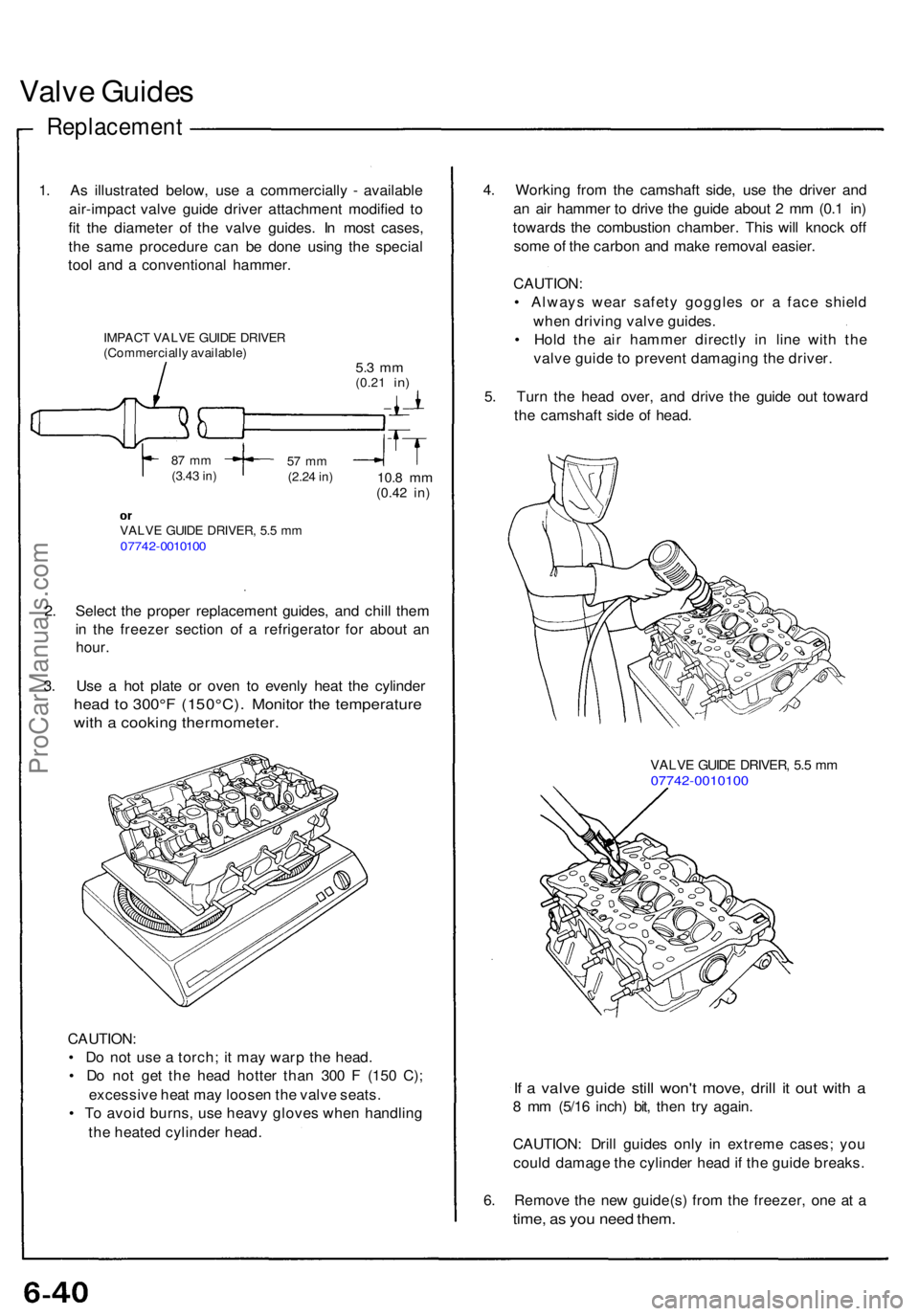
Valve Guide s
Replacemen t
1. A s illustrate d below , us e a commerciall y - availabl e
air-impac t valv e guid e drive r attachmen t modifie d t o
fi t th e diamete r o f th e valv e guides . I n mos t cases ,
th e sam e procedur e ca n b e don e usin g th e specia l
too l an d a conventiona l hammer .
IMPACT VALV E GUID E DRIVE R(Commerciall y available )5.3 m m(0.2 1 in)
87 m m(3.4 3 in)57 m m(2.2 4 in)10. 8 m m(0.4 2 in)
VALV E GUID E DRIVER , 5. 5 m m0774 2-001010 0
2. Selec t th e prope r replacemen t guides , an d chil l the m
i n th e freeze r sectio n o f a refrigerato r fo r abou t a n
hour .
3. Us e a ho t plat e o r ove n t o evenl y hea t th e cylinde r
head t o 300° F ( 150°C) . Monito r th e temperatur e
with a cookin g thermometer .
CAUTION:
• D o no t us e a torch ; i t ma y war p th e head .
• D o no t ge t th e hea d hotte r tha n 30 0 F (15 0 C) ;
excessiv e hea t ma y loose n th e valv e seats .
• T o avoi d burns , us e heav y glove s whe n handlin g
th e heate d cylinde r head . 4
. Workin g fro m th e camshaf t side , us e th e drive r an d
a n ai r hamme r t o driv e th e guid e abou t 2 m m (0. 1 in )
toward s th e combustio n chamber . Thi s wil l knoc k of f
som e o f th e carbo n an d mak e remova l easier .
CAUTION :
• Alway s wea r safet y goggle s o r a fac e shiel d
whe n drivin g valv e guides .
• Hol d th e ai r hamme r directl y i n lin e wit h th e
valv e guid e t o preven t damagin g th e driver .
5 . Tur n th e hea d over , an d driv e th e guid e ou t towar d
th e camshaf t sid e o f head .
VALV E GUID E DRIVER , 5. 5 m m07742-001010 0
If a valv e guid e stil l won' t move , dril l i t ou t wit h a
8 m m (5/1 6 inch ) bit , the n tr y again .
CAUTION : Dril l guide s onl y i n extrem e cases ; yo u
coul d damag e th e cylinde r hea d if th e guid e breaks .
6 . Remov e th e ne w guide(s ) fro m th e freezer , on e a t a
time , a s yo u nee d them .
ProCarManuals.com
Page 119 of 1640
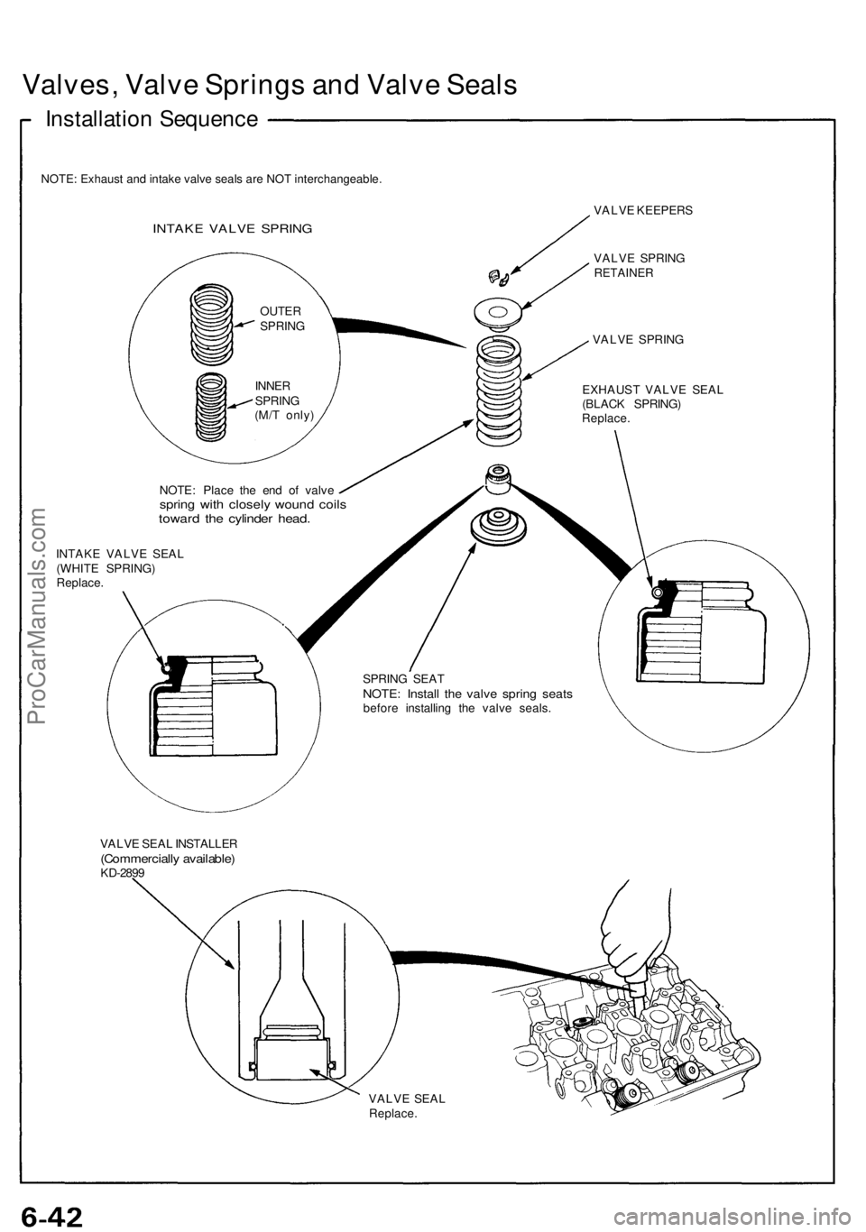
Valves, Valv e Spring s an d Valv e Seal s
Installatio n Sequenc e
NOTE: Exhaust and intake valve seals are NOT interchangeable.
INTAKE VALV E SPRIN G
VALVE KEEPER S
VALV E SPRIN G
RETAINE R
VALVE SPRIN G
EXHAUS T VALV E SEA L
(BLAC K SPRING )
Replace.
NOTE: Plac e th e en d o f valv espring wit h closel y woun d coil stowar d th e cylinde r head .
INTAK E VALV E SEA L
(WHIT E SPRING )
Replace .
SPRING SEA T
NOTE : Instal l th e valv e sprin g seat sbefor e installin g th e valv e seals .
VALV E SEA L INSTALLE R
(Commerciall y available )KD-2899
VALVE SEA L
Replace .
OUTER
SPRIN G
INNE R
SPRIN G
(M/ T only )
ProCarManuals.com