steering wheel adjustment ACURA NSX 1991 Service Repair Manual
[x] Cancel search | Manufacturer: ACURA, Model Year: 1991, Model line: NSX, Model: ACURA NSX 1991Pages: 1640, PDF Size: 60.48 MB
Page 429 of 1640
Installation
NOTE: Before installing the steering wheel, make sure
the front wheels are straight ahead.
CAUTION:
• Be sure to install the harness wires so that they are
not pinched or interfering with other car parts.
• Do not replace the original steering wheel with any
other design, since it will make it impossible to prop-
erly install the airbag. (Use only genuine Honda
replacement parts.)
• After reassembly, confirm that the wheels are still
straight ahead and that steering wheel spoke angle
is correct. If minor spoke angle adjustment is neces-
sary, adjust the tie-rods only. Do not remove and
reposition the steering wheel.
Confirm that the airbag assembly is securely
attached to the steering wheel; otherwise, severe per-
sonal injury could result during later airbag deploy-
ment.
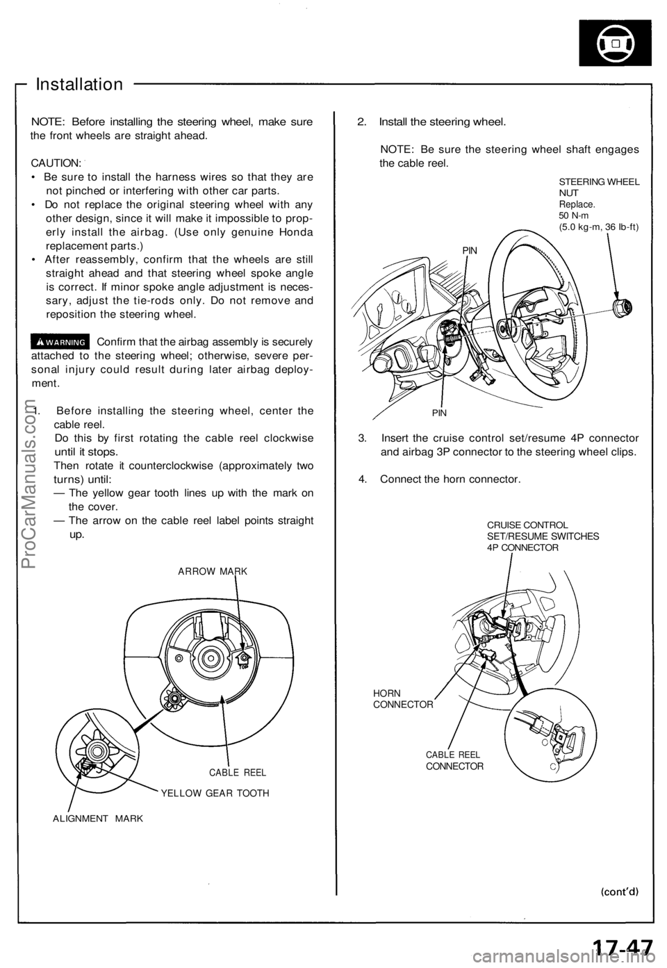
1. Before installing the steering wheel, center the
cable reel.
Do this by first rotating the cable reel clockwise
until it stops.
Then rotate it counterclockwise (approximately two
turns) until:
— The yellow gear tooth lines up with the mark on
the cover.
— The arrow on the cable reel label points straight
up.
ARROW MARK
CABLE REEL
YELLOW GEAR TOOTH
ALIGNMENT MARK
2. Install the steering wheel.
NOTE: Be sure the steering wheel shaft engages
the cable reel.
STEERING WHEEL
NUT
Replace.
50 N-m
(5.0 kg-m, 36 Ib-ft)
PIN
3. Insert the cruise control set/resume 4P connector
and airbag 3P connector to the steering wheel clips.
4. Connect the horn connector.
CRUISE CONTROL
SET/RESUME SWITCHES
4P CONNECTOR
HORN
CONNECTOR
CABLE REEL
CONNECTOR
PINProCarManuals.com
Page 558 of 1640
Steering angle sensor system check
1. Start the engine,
2. Push the TCS switch three times within three seconds.
NOTE: Always maintain the same number of rota-
tions.
3. Turn the steering wheel slowly from left to right more than 1.5 turns.
NOTE:
Start checking after the steering wheel moves at
least 1.5 turns from right to left.
Turn the steering wheel slowly, no faster than
one turn in four seconds.
4. Push the TCS switch twice within three seconds. NOTE: Always maintain the same number of rota-
tions.
5. Return the steering wheel to the left side slowly, and check the number of times the TCS indicator light
flashes after the wheel has moved approximately
one turn.
NOTE:
Start the check from the beginning when the steer-ing wheel moves at least one turn from left to
right, Turn the steering wheel slowly, no faster than one
turn in four seconds.
Standard number of times the TCS indicator light
flashes:
Manual Transmission: 5 times
Automatic Transmission: 2 times
6. If there is an abnormality, check the troubleshooting flowchart (see page 19-98('91-'93)('94-'96)
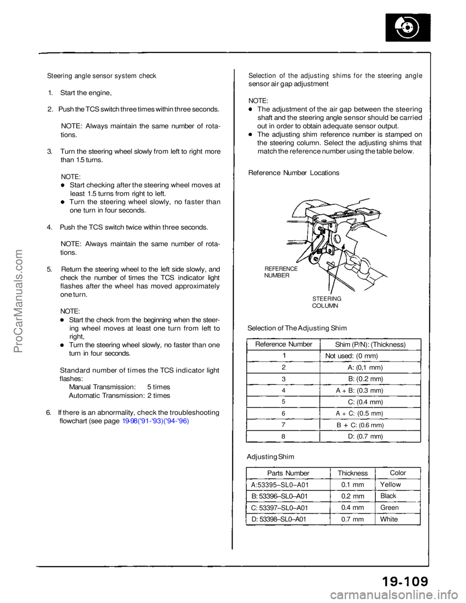
Selection of the adjusting shims for the steering angle
sensor air gap adjustment
NOTE:
The adjustment of the air gap between the steeringshaft and the steering angle sensor should be carried
out in order to obtain adequate sensor output.
The adjusting shim reference number is stamped on
the steering column. Select the adjusting shims that match the reference number using the table below.
Reference Number Locations
REFERENCE
NUMBER
STEERING
COLUMN
Selection of The Adjusting Shim
Adjusting Shim Parts Number
A:53395–SL0–A01
B: 53396–SL0–A01
C: 53397–SL0–A01
D: 53398–SL0–A01
Thickness
0.1 mm
0.2 mm
0.4 mm
0.7 mm
Color
Yellow
Black
Green
White
Reference Number
1
2
3
4
5
6
7
8
Shim (P/N): (Thickness)
Not used: (0 mm)
A:
(0,1
mm)
B:
(0.2
mm)
A + B:
(0.3
mm)
C:
(0.4
mm)
A + C:
(0.5
mm)
B + C:
(0.6
mm)
D:
(0.7
mm)ProCarManuals.com
Page 1303 of 1640
Steering Wheel
Installation
NOTE: Before installing the steering wheel, make sure
the front wheels are straight ahead.
CAUTION:
Be sure to install the harness wires so that they are
not pinched or interfering with other car parts.
Do not replace the original steering wheel with any
other design, since it will make it impossible to proper-
ly install the airbag. (Use only genuine HONDA
replacement parts.)
After reassembly, confirm that the wheels are still
straight ahead and that steering wheel spoke angle
is correct. If minor spoke angle adjustment is neces-
sary, adjust the tie-rods only. Do not remove and
reposition the steering wheel.
Confirm that the airbag assembly is secure-
ly attached to the steering wheel; otherwise, severe per-
sonal injury could result during later airbag deployment.
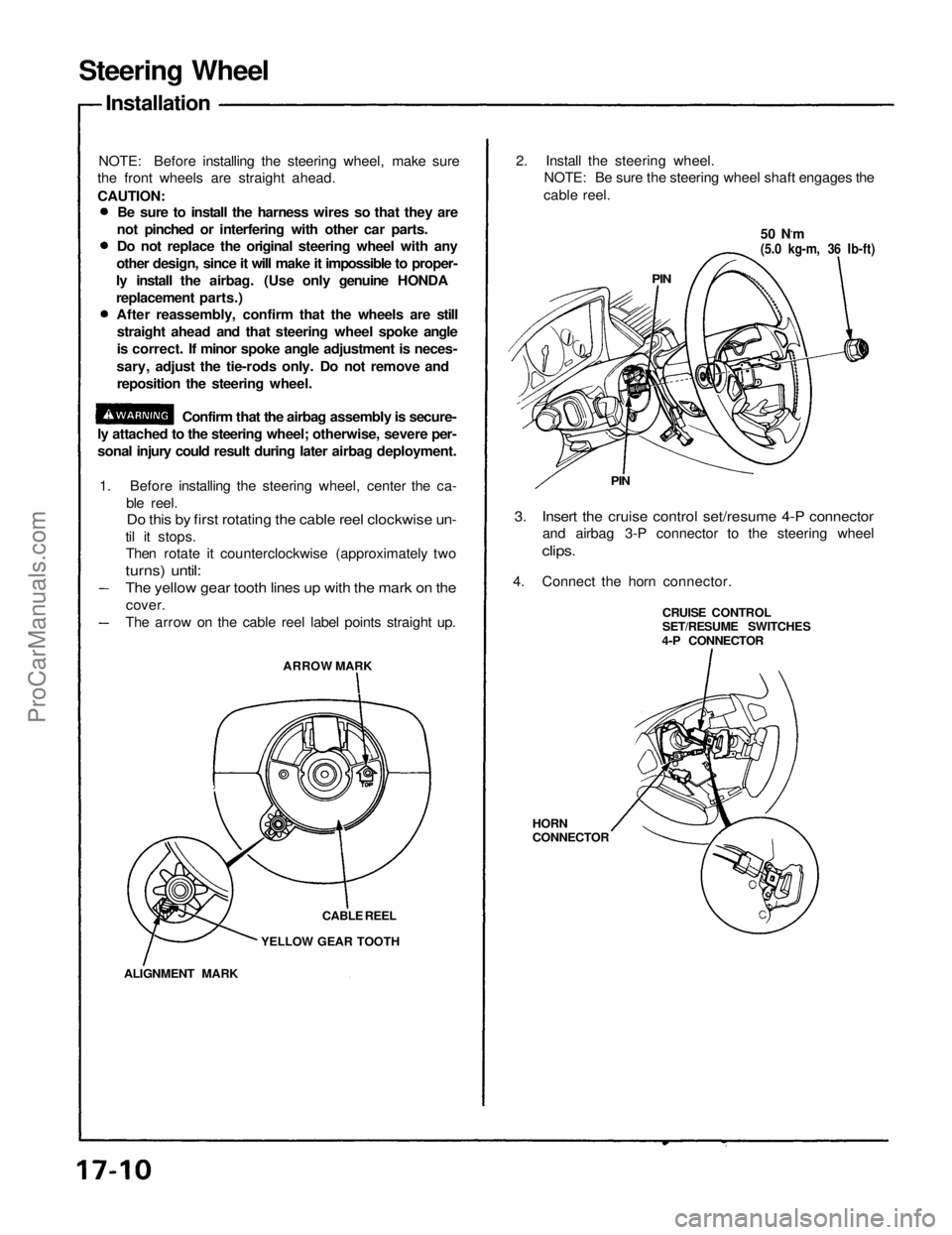
1. Before installing the steering wheel, center the ca-
ble reel.
Do this by first rotating the cable reel clockwise un-
til it stops.
Then rotate it counterclockwise (approximately two
turns) until:
ARROW MARK
CABLE REEL
YELLOW GEAR TOOTH
ALIGNMENT MARK
2. Install the steering wheel.
NOTE: Be sure the steering wheel shaft engages the
cable reel.
50 N.m
(5.0 kg-m, 36 Ib-ft)
PIN
PIN
3. Insert the cruise control set/resume 4-P connector
and airbag 3-P connector to the steering wheel
clips.
4. Connect the horn connector.
CRUISE CONTROL
SET/RESUME SWITCHES
4-P CONNECTOR
HORN
CONNECTOR
The yellow gear tooth lines up with the mark on the
cover.
The arrow on the cable reel label points straight up.ProCarManuals.com
Page 1339 of 1640
Component Location
Index
NOTE:
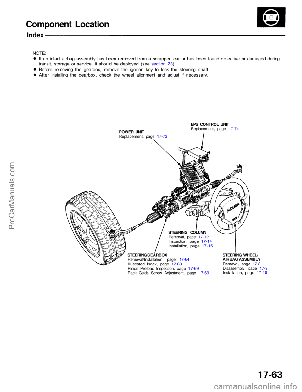
EPS CONTROL UNITReplacement, page 17-74
POWER UNIT
Replacement, page 17-73
STEERING WHEEL/
AIRBAG ASSEMBLYRemoval, page 17-8
Disassembly, page 17-9
Installation, page 17-10
STEERING COLUMN
Removal, page 17-12
Inspection, page 17-14
Installation, page 17-15
STEERING GEARBOX Removal/Installation, page 17-64
Illustrated Index, page 17-68
Pinion Preload Inspection, page 17-69
Rack Guide Screw Adjustment, page 17-69
If an intact airbag assembly has been removed from a scrapped car or has been found defective or damaged during
transit, storage or service, it should be deployed (see section 23).
Before removing the gearbox, remove the ignition key to lock the steering shaft.
After installing the gearbox, check the wheel alignment and adjust if necessary.ProCarManuals.com
Page 1556 of 1640
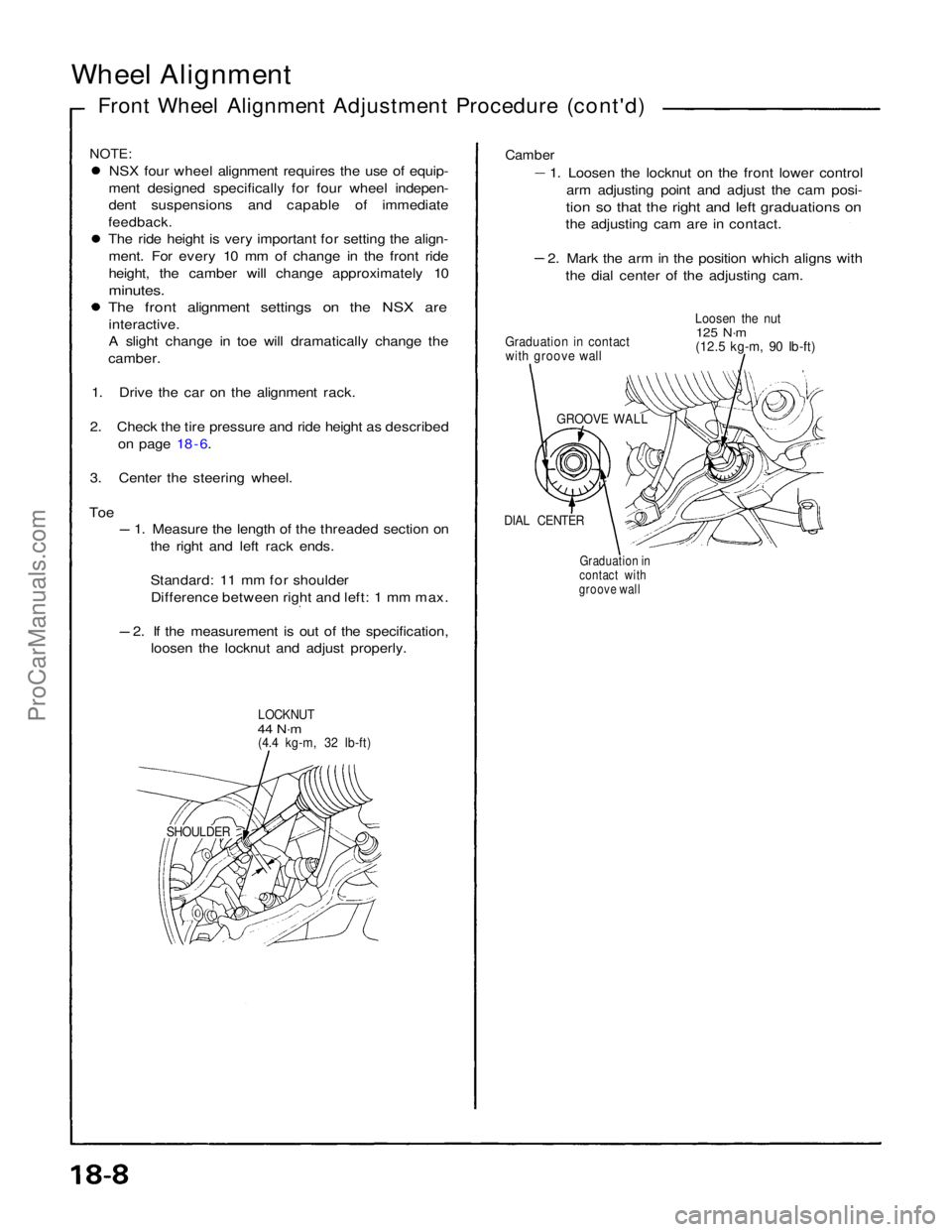
Wheel Alignment
Front Wheel Alignment Adjustment Procedure (cont'd)
NOTE:
NSX four wheel alignment requires the use of equip-
ment designed specifically for four wheel indepen-
dent suspensions and capable of immediate
feedback.
The ride height is very important for setting the align-
ment. For every 10 mm of change in the front ride
height, the camber will change approximately 10
minutes.
The front alignment settings on the NSX are
interactive.
A slight change in toe will dramatically change the
camber.
1. Drive the car on the alignment rack.
2. Check the tire pressure and ride height as described on page 18 - 6.
3. Center the steering wheel.
Toe
1. Measure the length of the threaded section on
the right and left rack ends.
Standard: 11 mm for shoulderDifference between right and left: 1 mm max. 2. If the measurement is out of the specification,
loosen the locknut and adjust properly.
LOCKNUT
44 N·m
(4.4 kg-m, 32 Ib-ft)
SHOULDERGraduation in
contact with
groove wall
DIAL CENTER
GROOVE WALL
Graduation in contact
with groove wall Loosen the nut
125 N·m
(12.5 kg-m, 90 Ib-ft)
Camber
1. Loosen the locknut on the front lower control
arm adjusting point and adjust the cam posi-
tion so that the right and left graduations on
the adjusting cam are in contact. 2. Mark the arm in the position which aligns with
the dial center of the adjusting cam.ProCarManuals.com