mirror ACURA NSX 1991 Service Repair Manual
[x] Cancel search | Manufacturer: ACURA, Model Year: 1991, Model line: NSX, Model: ACURA NSX 1991Pages: 1640, PDF Size: 60.48 MB
Page 85 of 1640
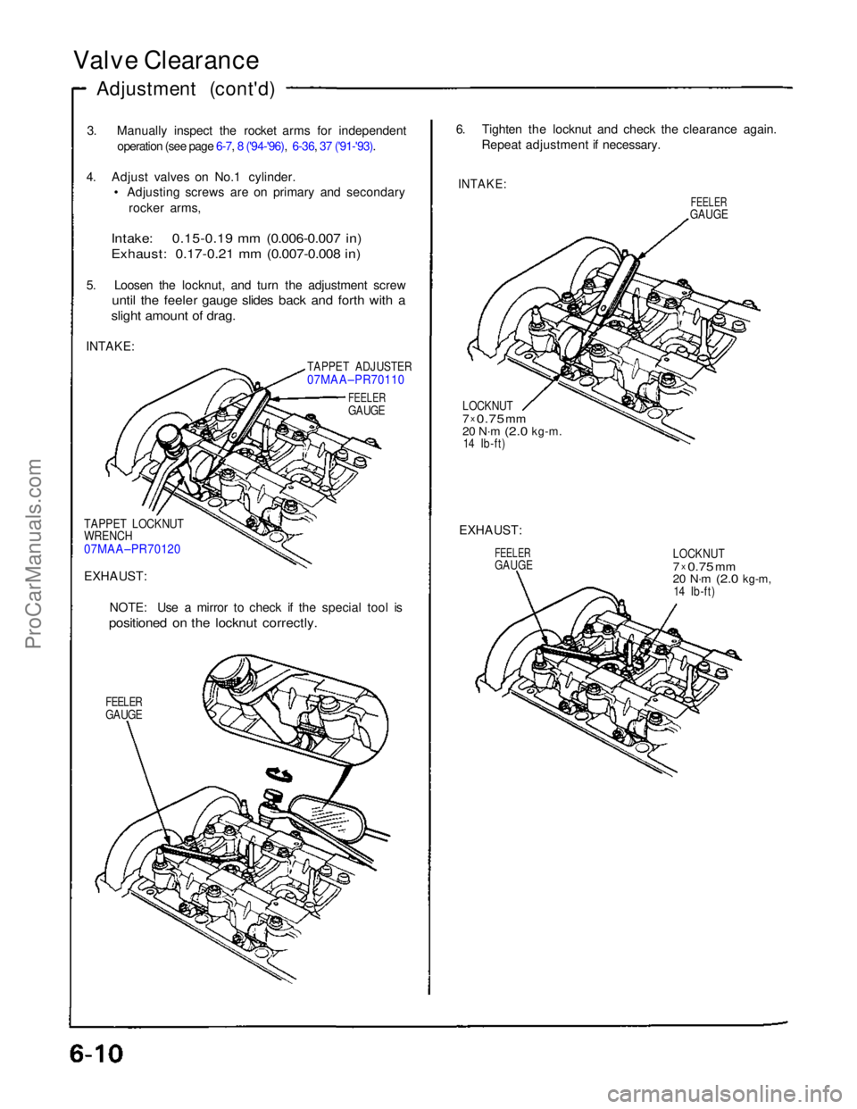
Valve Clearance
Adjustment (cont'd)
3. Manually inspect the rocket arms for independentoperation (see page 6-7, 8 ('94-'96), 6-36, 37 ('91-'93).
4. Adjust valves on No.1 cylinder.
• Adjusting screws are on primary and secondary
rocker arms,
Intake: 0.15-0.19 mm (0.006-0.007 in)
Exhaust: 0.17-0.21 mm (0.007-0.008 in)
5. Loosen the locknut, and turn the adjustment screw
until the feeler gauge slides back and forth with a
slight amount of drag.
INTAKE:
TAPPET ADJUSTER
07MAA–PR70110
FEELER
GAUGE
TAPPET LOCKNUT
WRENCH
07MAA–PR70120
EXHAUST: NOTE: Use a mirror to check if the special tool is
positioned on the locknut correctly.
FEELER
GAUGE
6. Tighten the locknut and check the clearance again.
Repeat adjustment if necessary.
INTAKE:
FEELER
GAUGE
LOCKNUT
7 x
0.75
mm
20 N·m
(2.0
kg-m.
14 Ib-ft)
EXHAUST:
FEELER
GAUGE
LOCKNUT
7
x
0.75
mm
20 N·m
(2.0
kg-m,
14 Ib-ft)ProCarManuals.com
Page 563 of 1640
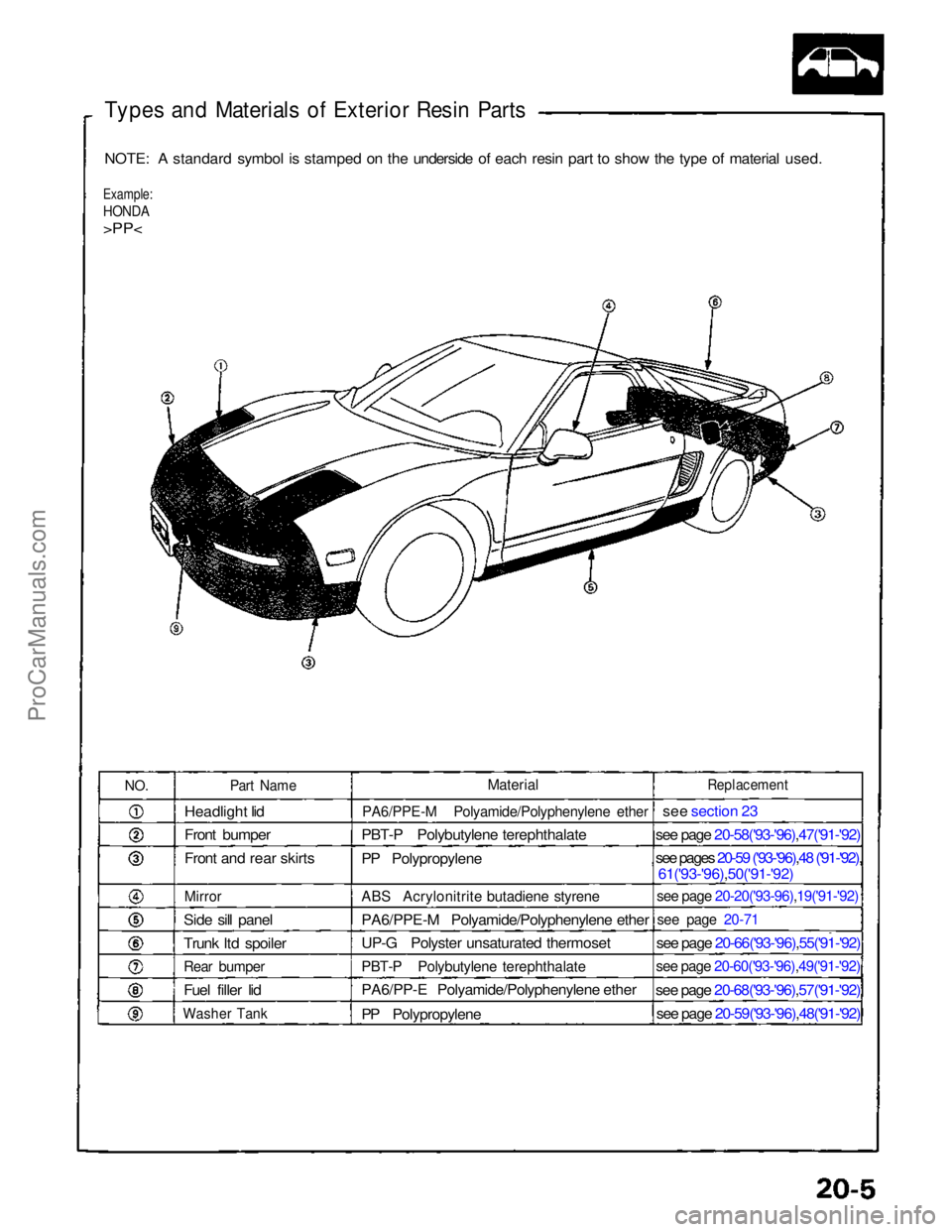
Types and Materials of Exterior Resin Parts
NOTE: A standard symbol is stamped on the underside of each resin part to show the type of material used.
Example:
HONDA
>PP<
NO.
Part Name
Headlight lid
Front bumper
Front and rear skirts
Mirror
Side sill panel
Trunk ltd spoiler
Rear bumper
Fuel filler lid
Washer Tank
Replacement
see section 23
see page 20-58('93-'96) ,47('91-'92)
see pages 20-59 ('93-'96),48 ('91-'92),
61('93-'96),50('91-'92)
see page 20-20('93-96) ,19('91-'92)
see page 20-71
see page 20-66('93-'96),55('91-'92)
see page 20-60('93-'96),49('91-'92)
see page 20-68('93-'96),57('91-'92)
see page 20-59('93-'96),48('91-'92)
Material
PA6/PPE-M Polyamide/Polyphenylene ether
PBT-P Polybutylene terephthalate
PP Polypropylene
ABS Acrylonitrite butadiene styrene
PA6/PPE-M Polyamide/Polyphenylene ether
UP-G Polyster unsaturated thermoset
PBT-P Polybutylene terephthalate
PA6/PP-E Polyamide/Polyphenylene ether
PP PolypropyleneProCarManuals.com
Page 564 of 1640
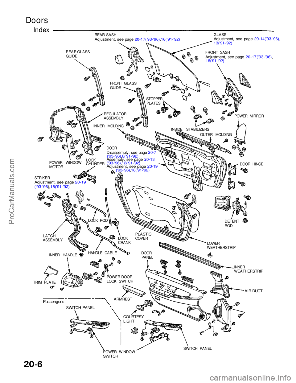
Doors
REAR SASH
Adjustment, see page 20-17('93-'96),16('91-'92)
REAR GLASS
GUIDE
Index
FRONT GLASS
GUIDE
REGULATOR
ASSEMBLY
INNER MOLDING STOPPER
PLATES GLASS
Adjustment, see page 20-14('93-'96),
13('91-'92)
FRONT SASH
Adjustment, see page 20-17('93-'96),
16('91-'92)
POWER MIRROR
INSIDE STABILIZERS OUTER MOLDING
DOOR HINGE
POWER WINDOW
MOTOR
LOCK
CYLINDER
DOOR
Disassembly, see page 20-7
('93-'96),6('91-'92)
Assembly, see page 20-13
('93-'96),12('91-'92)
Adjustment, see page 20-19
('93-'96),18('91-'92)
STRIKER
Adjustment, see page 20-19
('93-'96),18('91-'92)
LOCK ROD
LATCH
ASSEMBLY INNER HANDLE HANDLE CABLE
TRIM PLATE POWER DOOR
LOCK SWITCHDOOR
PANEL
LOCK
CRANK
PLASTIC
COVER
DETENT
ROD
LOWER
WEATHERSTRIP
INNER
WEATHERSTRIP
AIR DUCT
Passenger's:
SWITCH PANEL
ARMREST
COURTESY
LIGHT
SWITCH PANEL
POWER WINDOW
SWITCHProCarManuals.com
Page 578 of 1640
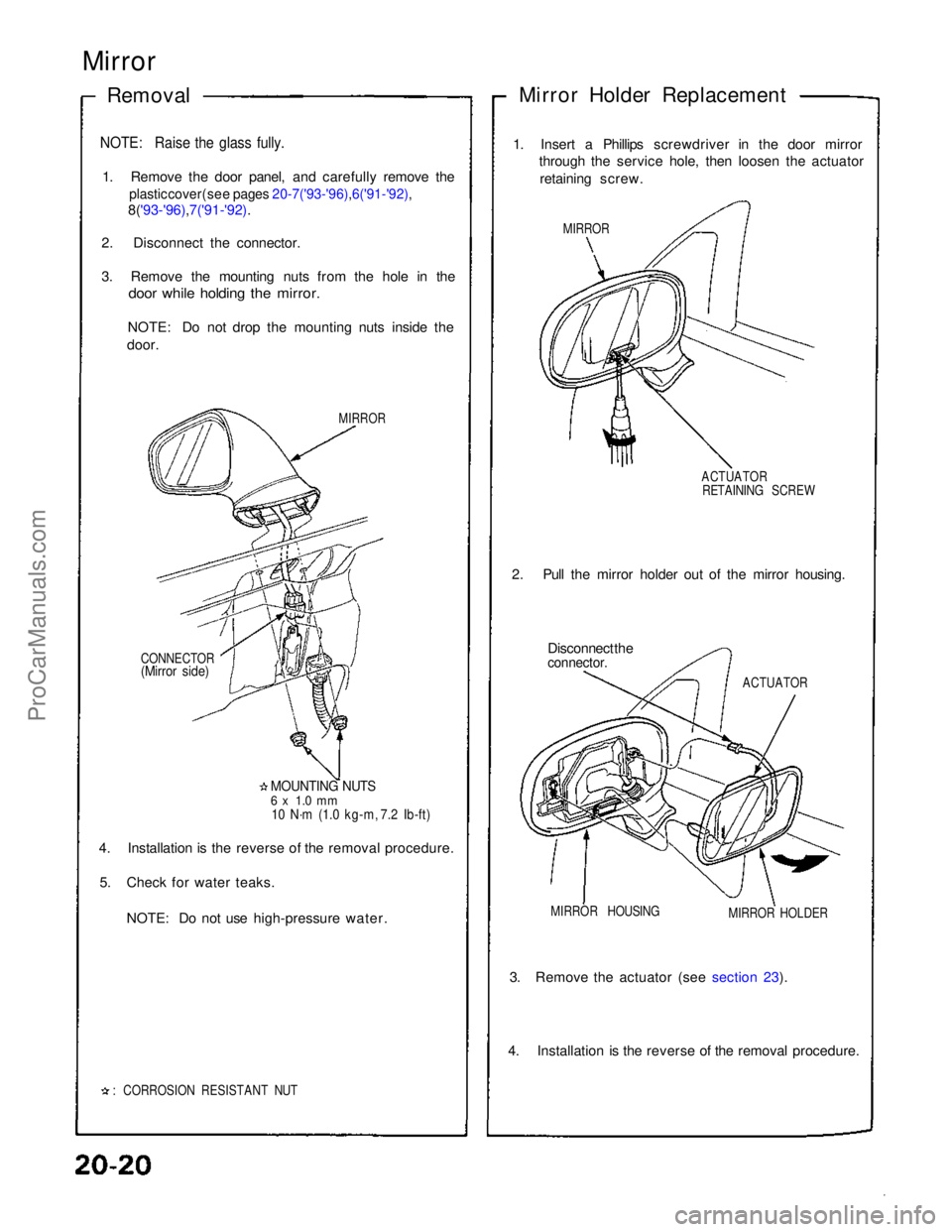
Mirror
Removal Mirror Holder Replacement
1. Insert a Phillips screwdriver in the door mirror through the service hole, then loosen the actuator
retaining screw.
MIRROR
ACTUATORRETAINING SCREW
2. Pull the mirror holder out of the mirror housing. Disconnect the
connector.
ACTUATOR
MIRROR HOLDER
MIRROR HOUSING
3. Remove the actuator (see section 23).
4. Installation is the reverse of the removal procedure.
: CORROSION RESISTANT NUT
4. Installation is the reverse of the removal procedure.
5. Check for water teaks.
NOTE: Do not use high-pressure water.
MOUNTING NUTS
6 x 1.0 mm
10 N·m (1.0 kg-m, 7.2 Ib-ft)
CONNECTOR
(Mirror side)
MIRROR
NOTE: Raise the glass fully.
1. Remove the door panel, and carefully remove the
plastic cover (see pages 20-7('93-'96) ,6('91-'92),
8('93-'96),7('91-'92).
2. Disconnect the connector.
3. Remove the mounting nuts from the hole in the
door while holding the mirror.
NOTE: Do not drop the mounting nuts inside the
door.ProCarManuals.com
Page 581 of 1640
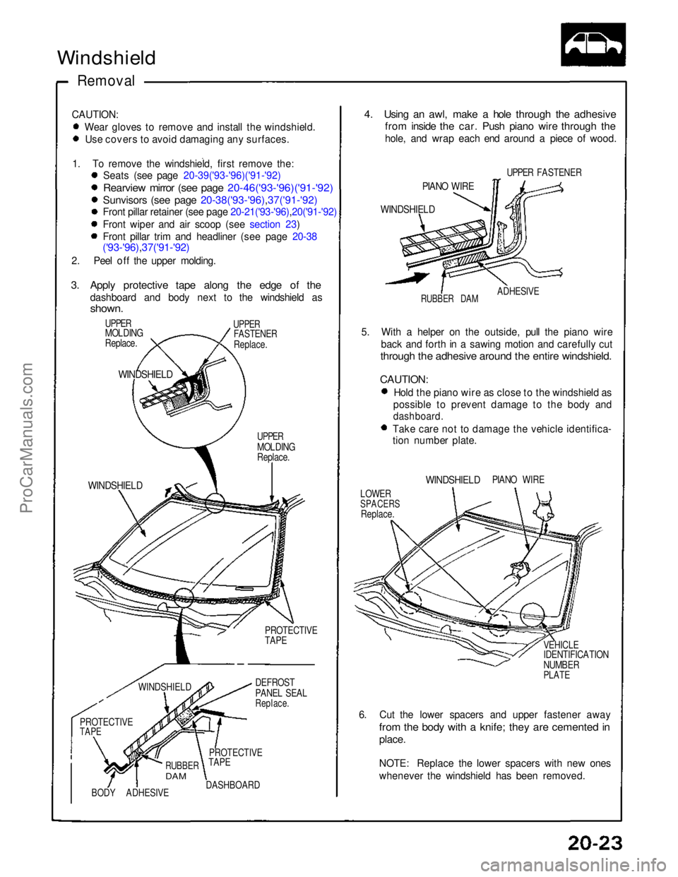
Windshield
Removal
CAUTION: Wear gloves to remove and install the windshield. Use covers to avoid damaging any surfaces.
1. To remove the windshield, first remove the: Seats (see page 20-39('93-'96)('91-'92)
Rearview mirror (see page 20-46('93-'96)('91-'92)
Sunvisors (see page 20-38('93-'96),37('91-'92)
Front pillar retainer (see page 20-21('93-'96),20('91-'92)
Front wiper and air scoop (see section 23)
Front pillar trim and headliner (see page 20-38
('93-'96),37('91-'92)
2. Peel off the upper molding.
3. Apply protective tape along the edge of the
dashboard and body next to the windshield as
shown.
UPPER
MOLDING
Replace.
UPPER
FASTENER
Replace.
WINDSHIELD
UPPER
MOLDING
Replace.
WINDSHIELD
PROTECTIVE
TAPE
WINDSHIELD
DEFROST
PANEL SEAL
Replace.
PROTECTIVE
TAPE
BODY
ADHESIVE
RUBBER
DAM
DASHBOARD
PROTECTIVE
TAPE
4. Using an awl, make a hole through the adhesive
from inside the car. Push piano wire through the
hole, and wrap each end around a piece of wood.
UPPER FASTENER
PIANO WIRE
WINDSHIELD
ADHESIVE
RUBBER DAM
5. With a helper on the outside, pull the piano wire back and forth in a sawing motion and carefully cut
through the adhesive around the entire windshield.
CAUTION:
Hold the piano wire as close to the windshield as
possible to prevent damage to the body and
dashboard.
Take care not to damage the vehicle identifica-
tion number plate.
WINDSHIELD
PIANO WIRE
LOWER
SPACERS
Replace.
VEHICLE
IDENTIFICATION
NUMBER
PLATE
6. Cut the lower spacers and upper fastener away
from the body with a knife; they are cemented in
place.
NOTE: Replace the lower spacers with new ones
whenever the windshield has been removed.ProCarManuals.com
Page 896 of 1640
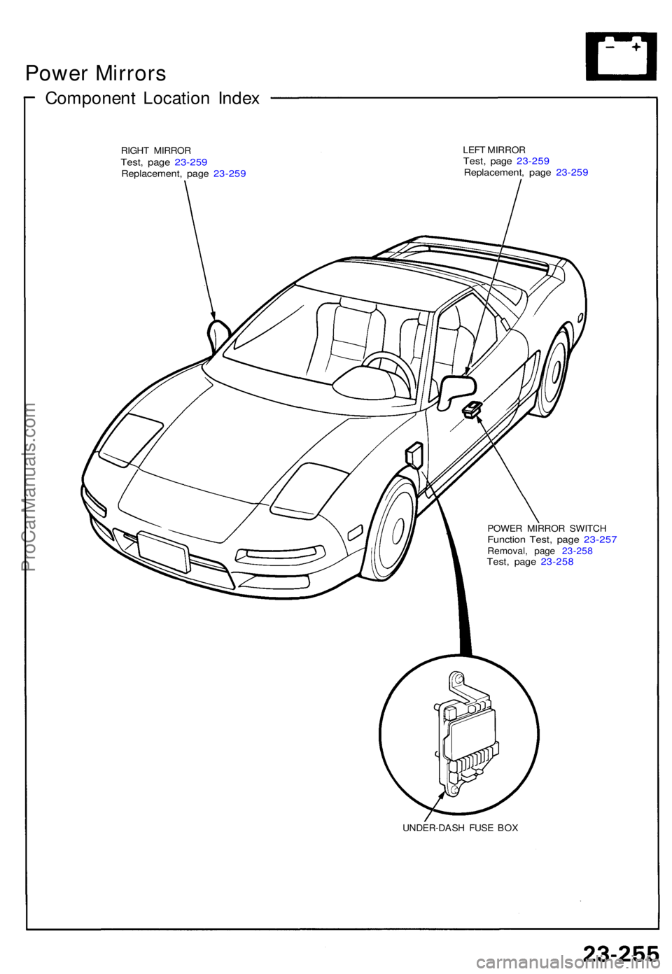
Power Mirror s
Componen t Locatio n Inde x
RIGH T MIRRO RTest, pag e 23-25 9Replacement , pag e 23-25 9
LEFT MIRRO RTest, pag e 23-25 9Replacement , pag e 23-25 9
POWE R MIRRO R SWITC HFunction Test , pag e 23-25 7Removal , pag e 23-25 8Test, pag e 23-25 8
UNDER-DAS H FUS E BO X
ProCarManuals.com
Page 897 of 1640
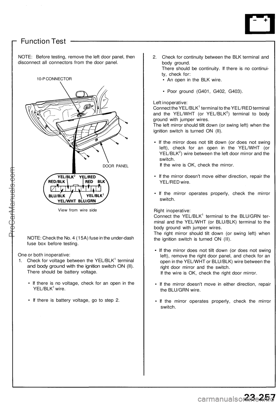
Function Test
NOTE: Before testing, remove the left door panel, then
disconnect all connectors from the door panel.
10-P CONNECTOR
DOOR PANEL
View from wire side
NOTE: Check the No. 4 (15A) fuse in the under-dash
fuse box before testing.
One or both inoperative:
1. Check for voltage between the YEL/BLK1 terminal
and body ground with the ignition switch ON (II).
There should be battery voltage.
• If there is no voltage, check for an open in the
YEL/BLK1 wire.
• If there is battery voltage, go to step 2.
2. Check for continuity between the BLK terminal and
body ground.
There should be continuity. If there is no continui-
ty, check for:
• An open in the BLK wire.
• Poor ground (G401, G402, G403).
Left inoperative:
Connect the YEL/BLK1 terminal to the YEL/RED terminal
and the YEL/WHT (or YEL/BLK2) terminal to body
ground with jumper wires.
The
left mirror should
tilt
down
(or
swing left) when
the
ignition switch is turned ON (II).
• If the
mirror
does
not
tilt
down
(or
does
not
swing
left), check for an open in the YEL/WHT (or
YEL/BLK2) wire between the left door mirror and the
switch.
If the wire is OK, check the mirror.
• If the mirror doesn't move either direction, repair the
YEL/RED wire.
• If the mirror operates properly, check the mirror
switch.
Right inoperative:
Connect the YEL/BLK1 terminal to the BLU/GRN ter-
minal and the YEL/WHT (or BLU/BLK) terminal to the
body ground with jumper wires.
The right mirror should tilt down (or swing left) when
the ignition switch is turned ON (II).
• If the
mirror does
not
tilt
down
(or
does
not
swing
left), remove the right door panel, and check for an
open in the YEL/WHT or BLU/BLK) wire between the
right door mirror and the switch.
If the wire is OK, check the right door mirror.
• If the mirror doesn't move in either direction, repair
the BLU/GRN wire.
• If the mirror operates properly, check the mirror
switch.ProCarManuals.com
Page 898 of 1640
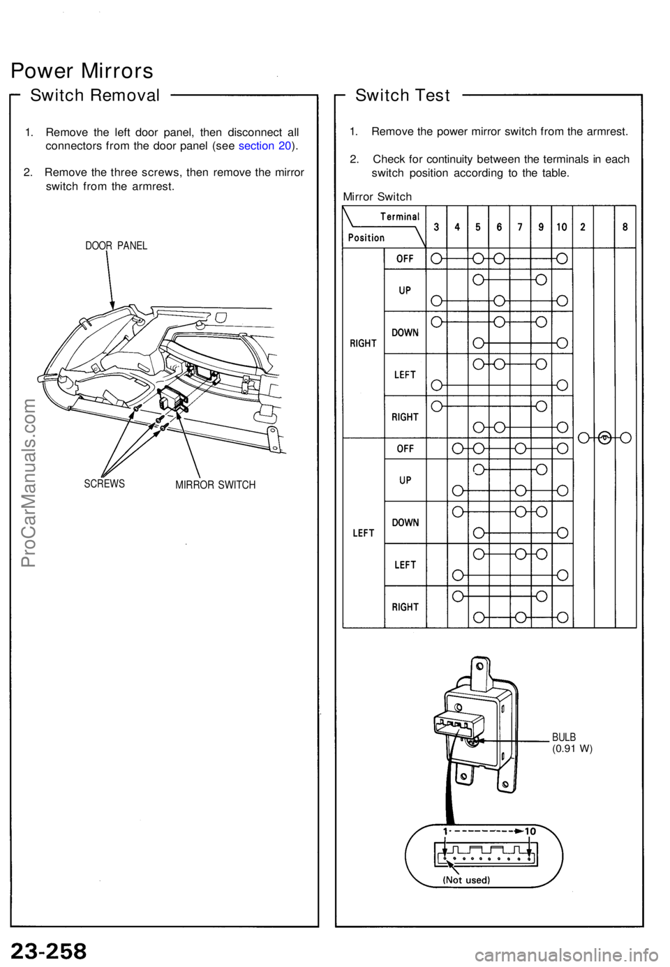
Power Mirror s
Switch Remova l
1. Remov e th e lef t doo r panel , the n disconnec t al l
connector s fro m th e doo r pane l (se e sectio n 20 ).
2 . Remov e th e thre e screws , the n remov e th e mirro r
switc h fro m th e armrest .
DOOR PANE L
SCREW S
MIRROR SWITC H
Switch Tes t
1. Remov e th e powe r mirro r switc h fro m th e armrest .
2 . Chec k fo r continuit y betwee n th e terminal s i n eac h
switc h positio n accordin g t o th e table .
Mirro r Switc h
BULB(0.91 W)
ProCarManuals.com
Page 899 of 1640
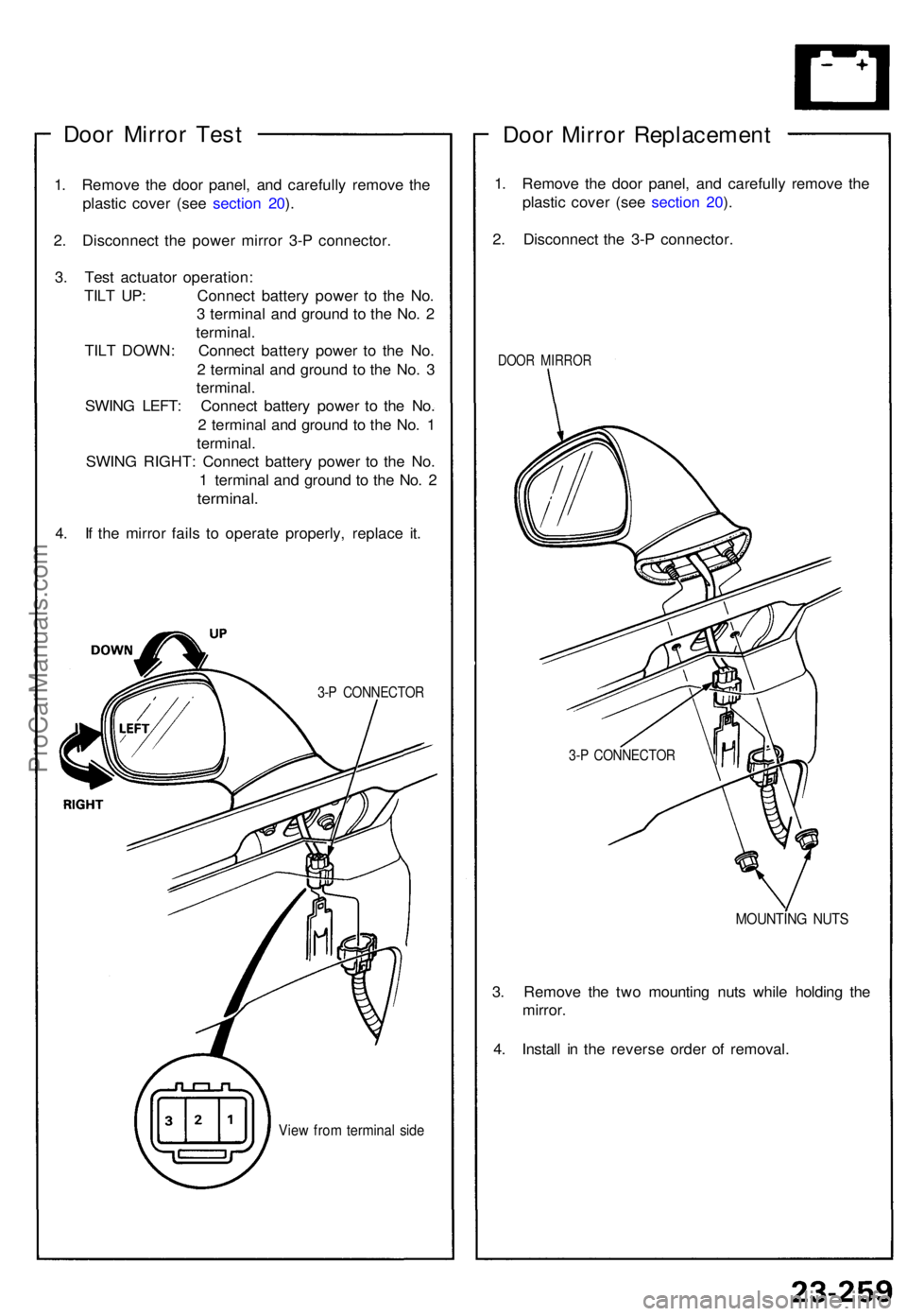
Door Mirro r Tes t
1. Remov e th e doo r panel , an d carefull y remov e th e
plasti c cove r (se e sectio n 20 ).
2 . Disconnec t th e powe r mirro r 3- P connector .
3 . Tes t actuato r operation :
TIL T UP : Connec t batter y powe r t o th e No .
3 termina l an d groun d t o th e No . 2
terminal .
TIL T DOWN : Connec t batter y powe r t o th e No .
2 termina l an d groun d t o th e No . 3
terminal .
SWIN G LEFT : Connec t batter y powe r t o th e No .
2 termina l an d groun d t o th e No . 1
terminal .
SWIN G RIGHT : Connec t batter y powe r t o th e No .
1 termina l an d groun d t o th e No . 2
terminal .
4. I f th e mirro r fail s t o operat e properly , replac e it .
3-P CONNECTO R
View fro m termina l sid e
Doo r Mirro r Replacemen t
1. Remov e th e doo r panel , an d carefull y remov e th e
plasti c cove r (se e sectio n 20 ).
2 . Disconnec t th e 3- P connector .
DOOR MIRRO R
MOUNTIN G NUT S
3. Remov e th e tw o mountin g nut s whil e holdin g th e
mirror .
4 . Instal l i n th e revers e orde r o f removal .
3-P CONNECTO R
ProCarManuals.com
Page 900 of 1640
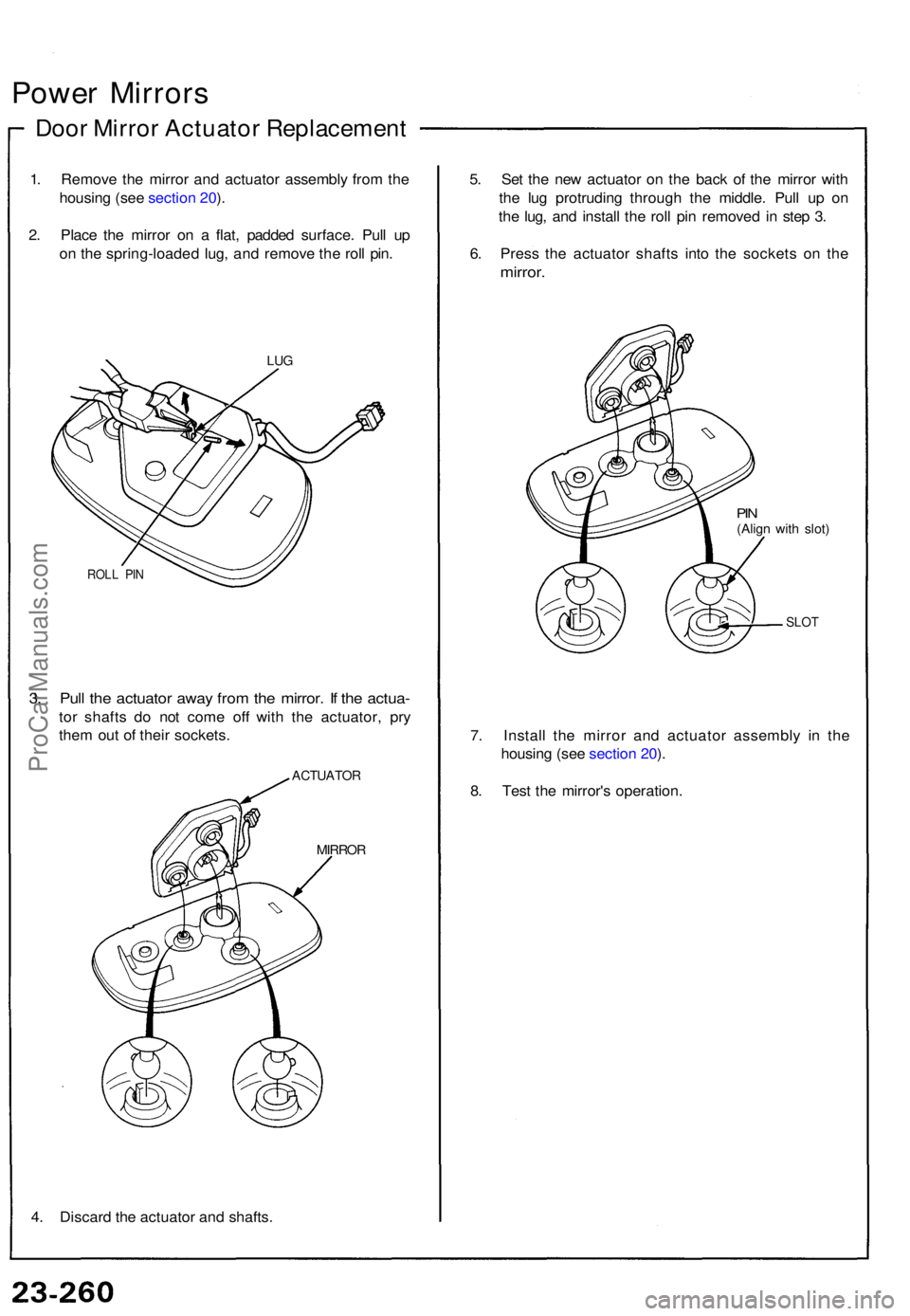
Power Mirror s
Door Mirro r Actuato r Replacemen t
1. Remov e th e mirro r an d actuato r assembl y fro m th e
housin g (se e sectio n 20 ).
2 . Plac e th e mirro r o n a flat , padde d surface . Pul l u p
o n th e spring-loade d lug , an d remov e th e rol l pin .
LUG
ROL L PI N
3. Pul l th e actuato r awa y fro m th e mirror . I f th e actua -
tor shaft s d o no t com e of f wit h th e actuator , pr y
the m ou t o f thei r sockets .
ACTUATO R
MIRROR
4. Discar d th e actuato r an d shafts . 5
. Se t th e ne w actuato r o n th e bac k o f th e mirro r wit h
th e lu g protrudin g throug h th e middle . Pul l u p o n
th e lug , an d instal l th e rol l pi n remove d i n ste p 3 .
6 . Pres s th e actuato r shaft s int o th e socket s o n th e
mirror .
PIN(Alig n wit h slot )
SLO T
7. Instal l th e mirro r an d actuato r assembl y i n th e
housin g (se e sectio n 20 ).
8 . Tes t th e mirror' s operation .
ProCarManuals.com