wipers ACURA NSX 1991 Service Repair Manual
[x] Cancel search | Manufacturer: ACURA, Model Year: 1991, Model line: NSX, Model: ACURA NSX 1991Pages: 1640, PDF Size: 60.48 MB
Page 926 of 1640
Wipers/Washers
Component Location Index
SRS components are located in this area. Review theSRS component locations, precautions, and procedures
in the SRS section (24) before performing repairs or ser-
vice.
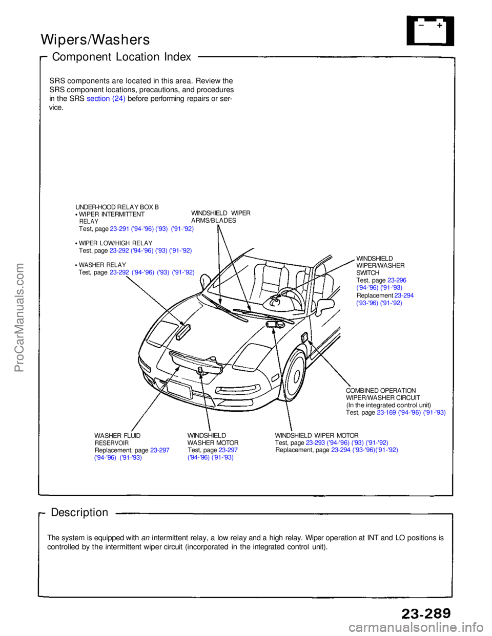
UNDER-HOOD RELAY BOX BWIPER INTERMITTENT
RELAY
Test, page 23-291 ('94-'96) ('93) ('91-'92)
WIPER LOW/HIGH RELAY
Test, page 23-292 ('94-'96) ('93) ('91-'92)
WASHER RELAY
Test, page 23-292 ('94-'96) ('93) ('91-'92) WINDSHIELD WIPER
ARMS/BLADES
WASHER FLUID
RESERVOIR
Replacement, page 23-297
('94-'96) ('91-'93)
WINDSHIELD
WASHER MOTOR
Test, page 23-297
('94-'96) ('91-'93) WINDSHIELD WIPER MOTOR
Test, page 23-293 ('94-'96) ('93) ('91-'92)
Replacement, page 23-294 ('93-'96)('91-'92) COMBINED OPERATION
WIPER/WASHER CIRCUIT
(In the integrated control unit)
Test, page 23-169 ('94-'96) ('91-'93)
Description
The system is equipped with an intermittent relay, a low relay and a high relay. Wiper operation at INT and LO positions is
controlled by the intermittent wiper circuit (incorporated in the integrated control unit). WINDSHIELD
WIPER/WASHER
SWITCH
Test, page 23-296
('94-'96) ('91-'93)
Replacement 23-294
('93-'96) ('91-'92)ProCarManuals.com
Page 928 of 1640
Wipers/Washers
High Relay/Washer Relay Test
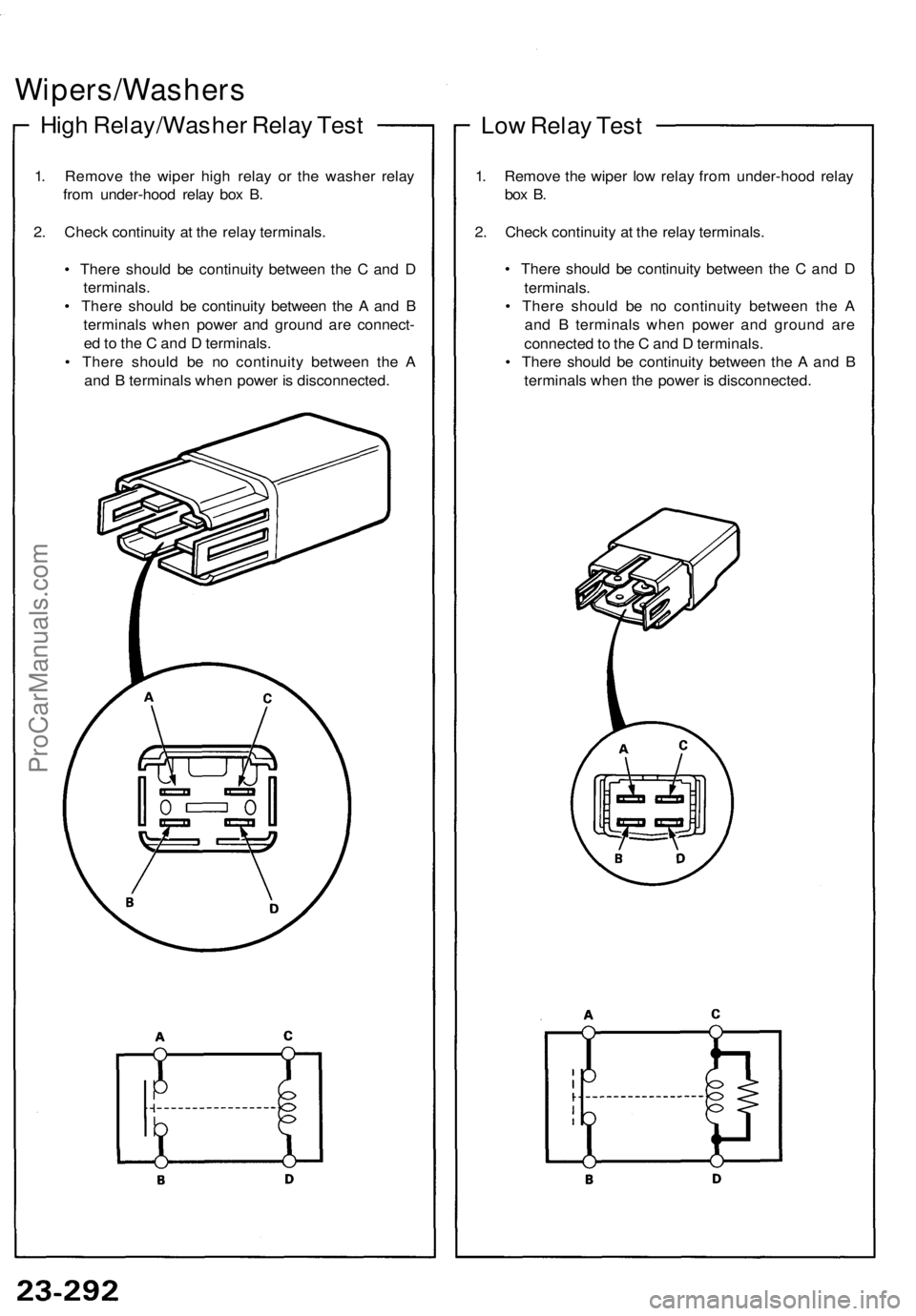
1. Remove the wiper high relay or the washer relay
from under-hood relay box B.
2. Check continuity at the relay terminals.
• There should be continuity between the C and D
terminals.
• There should be continuity between the A and B
terminals when power and ground are connect-
ed to the C and D terminals.
• There should be no continuity between the A
and B terminals when power is disconnected.
Low Relay Test
1. Remove the wiper low relay from under-hood relay
box B.
2. Check continuity at the relay terminals.
• There should be continuity between the C and D
terminals.
• There should be no continuity between the A
and B terminals when power and ground are
connected to the C and D terminals.
• There should be continuity between the A and B
terminals when the power is disconnected.ProCarManuals.com
Page 930 of 1640
Wipers/Washers
Windshield Wiper MotorReplacement
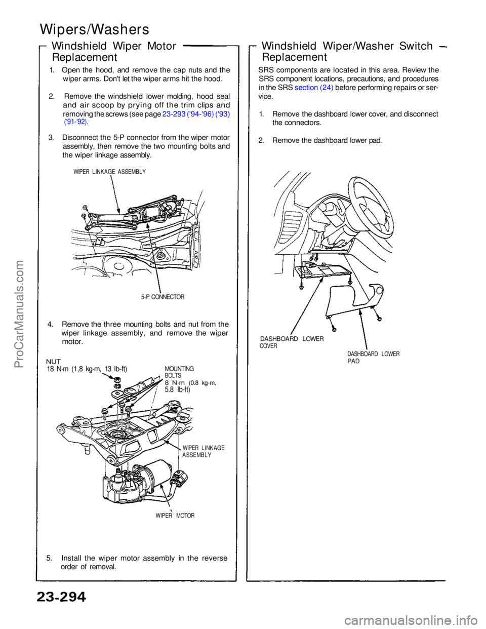
1. Open the hood, and remove the cap nuts and the wiper arms. Don't let the wiper arms hit the hood.
2. Remove the windshield lower molding, hood seal
and air scoop by prying off the trim clips and
removing the screws (see page 23-293 ('94-'96) ('93)
('91-'92).
3. Disconnect the 5-P connector from the wiper motor assembly, then remove the two mounting bolts and
the wiper linkage assembly.
WIPER LINKAGE ASSEMBLY
5-P CONNECTOR
4. Remove the three mounting bolts and nut from the wiper linkage assembly, and remove the wiper
motor.
MOUNTING
BOLTS
8 N·m
(0.8 kg-m,
5.8 Ib-ft)
NUT
18 N·m (1,8 kg-m, 13 Ib-ft)
WIPER LINKAGE
ASSEMBLY
WIPER MOTOR
5. Install the wiper motor assembly in the reverse order of removal.
DASHBOARD LOWER
PAD
DASHBOARD LOWER
COVER
Windshield Wiper/Washer Switch
Replacement
SRS components are located in this area. Review the SRS component locations, precautions, and procedures
in the SRS section (24) before performing repairs or ser-
vice.
1. Remove the dashboard lower cover, and disconnect the connectors.
2. Remove the dashboard lower pad.ProCarManuals.com
Page 931 of 1640
Wipers/Washers
Windshield Wiper/Washe r Switc h Tes t
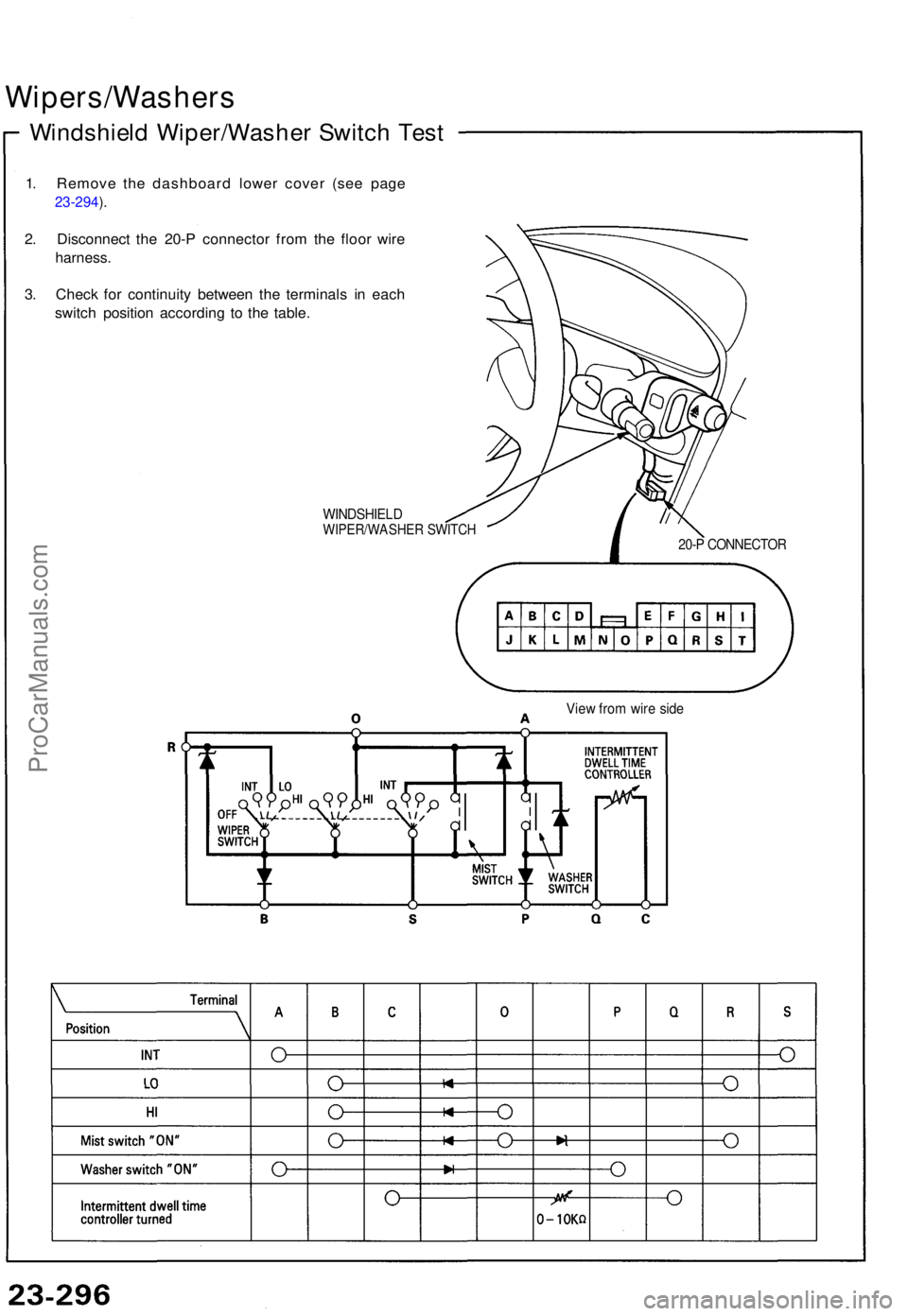
1. Remov e th e dashboar d lowe r cove r (se e pag e
23-294 ).
2 . Disconnec t th e 20- P connecto r fro m th e floo r wir e
harness .
3. Chec k fo r continuit y betwee n th e terminal s i n eac h
switc h positio n accordin g t o th e table .
WINDSHIEL DWIPER/WASHE R SWITC H20-P CONNECTO R
View fro m wir e sid e
ProCarManuals.com
Page 1434 of 1640
Wipers/Washers
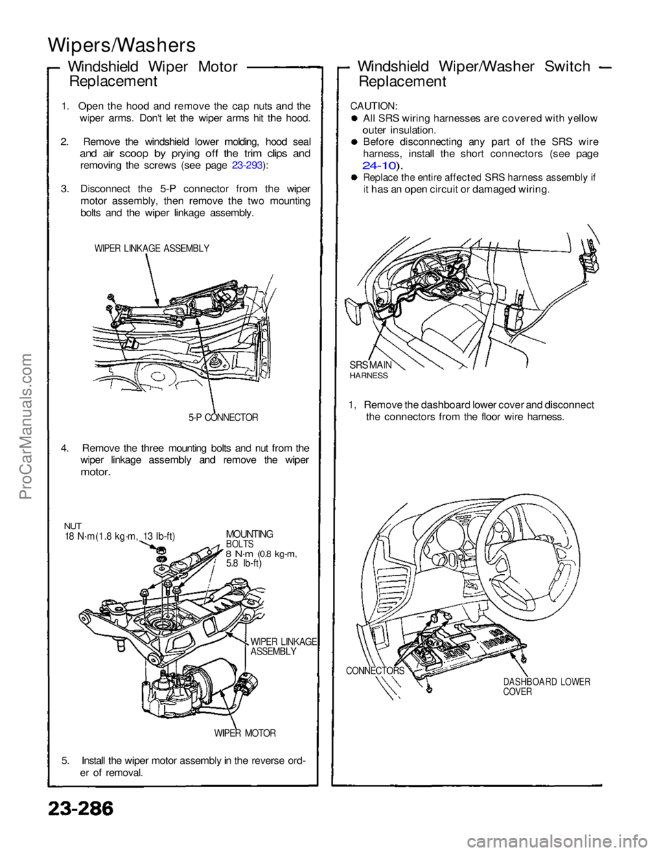
Windshield Wiper MotorReplacement
1. Open the hood and remove the cap nuts and the wiper arms. Don't let the wiper arms hit the hood.
2. Remove the windshield lower molding, hood seal
and air scoop by prying off the trim clips and
removing the screws (see page 23-293):
3. Disconnect the 5-P connector from the wiper motor assembly, then remove the two mounting
bolts and the wiper linkage assembly.
WIPER LINKAGE ASSEMBLY
5-P CONNECTOR
4. Remove the three mounting bolts and nut from the wiper linkage assembly and remove the wiper
motor.
NUT
18 N·m(1.8 kg·m, 13 lb-ft)
MOUNTING
BOLTS
8 N·m
(0.8 kg-m,
5.8 Ib-ft)
WIPER LINKAGE
ASSEMBLY
WIPER MOTOR
5. Install the wiper motor assembly in the reverse ord- er of removal. Windshield Wiper/Washer Switch
Replacement
CAUTION:
All SRS wiring harnesses are covered with yellow
outer insulation. Before disconnecting any part of the SRS wire
harness, install the short connectors (see page
24-10).
Replace the entire affected SRS harness assembly if
it has an open circuit or damaged wiring.
SRS MAIN
HARNESS
1, Remove the dashboard lower cover and disconnect the connectors from the floor wire harness.
CONNECTORS
DASHBOARD LOWER
COVERProCarManuals.com
Page 1436 of 1640
Wipers/Washers
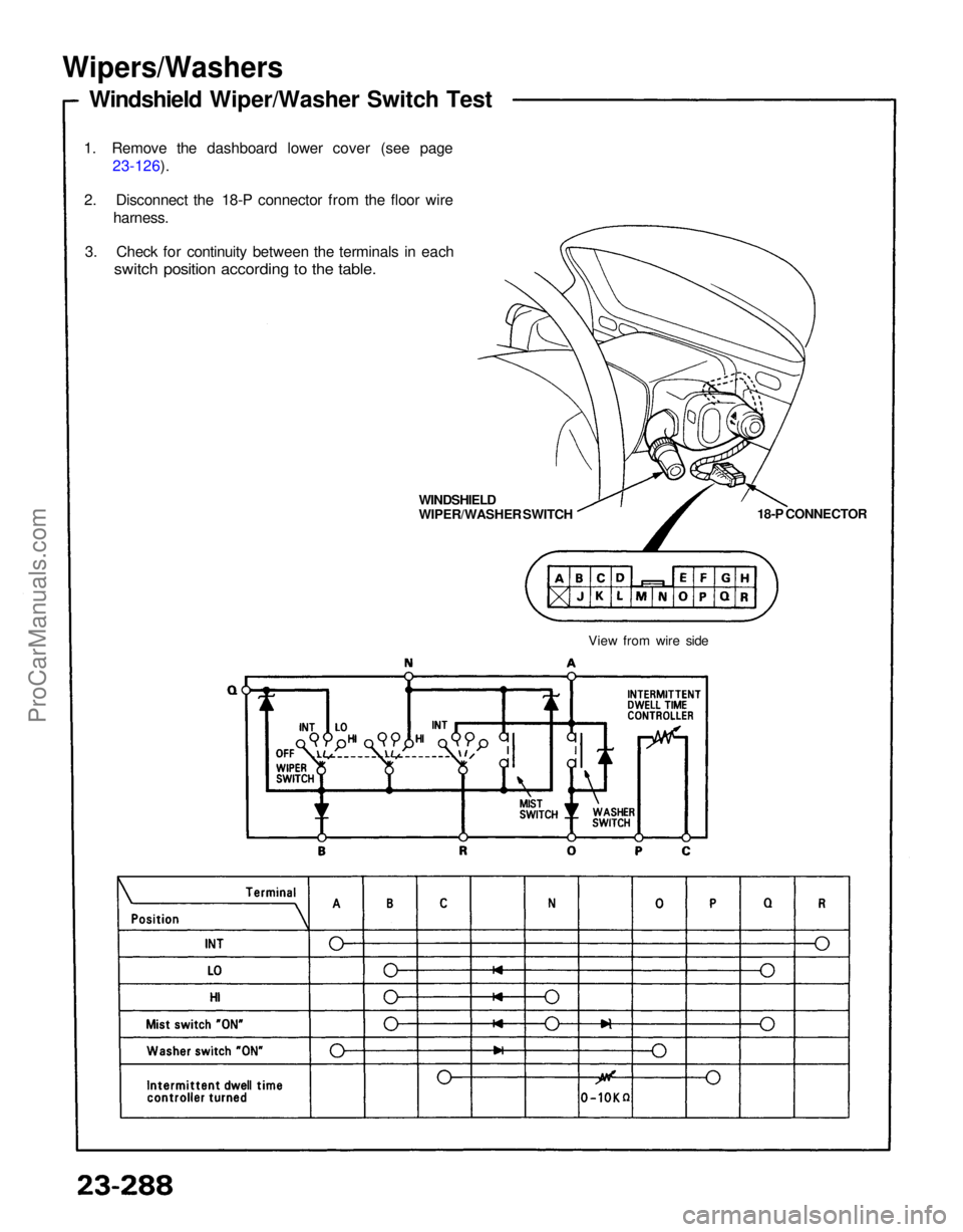
Windshield Wiper/Washer Switch Test
1. Remove the dashboard lower cover (see page 23-126).
2. Disconnect the 18-P connector from the floor wire harness.
3. Check for continuity between the terminals in each
switch position according to the table.
18-P CONNECTOR
WINDSHIELD
WIPER/WASHER SWITCH
View from wire sideProCarManuals.com
Page 1622 of 1640
Wipers/Washers
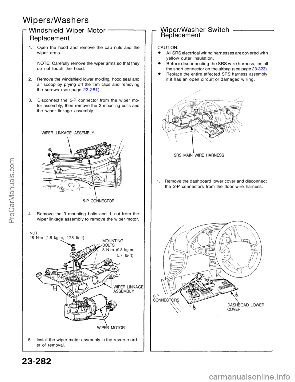
Windshield Wiper Motor
Replacement
1. Open the hood and remove the cap nuts and the wiper arms.
NOTE: Carefully remove the wiper arms so that they
do not touch the hood.
2. Remove the windshield lower molding, hood seal and air scoop by prying off the trim clips and removing
the screws (see page 23-281).
3. Disconnect the 5-P connector from the wiper mo- tor assembly, then remove the 2 mounting bolts and
the wiper linkage assembly.
WIPER LINKAGE ASSEMBLY
5-P CONNECTOR
4. Remove the 3 mounting bolts and 1 nut from the wiper linkage assembly to remove the wiper motor.
NUT
18 N·m (1.8 kg-m, 12.8 Ib-ft)
MOUNTING
BOLTS
8 N·m
(0.8 kg-m.
5.7 Ib-ft)
WIPER LINKAGE
ASSEMBLY
WIPER MOTOR
5. Install the wiper motor assembly in the reverse ord- er of removal. Wiper/Washer Switch
Replacement
CAUTION: All SRS electrical wiring harnesses are covered with
yellow outer insulation.Before disconnecting the SRS wire harness, install
the short connector on the airbag (see page 23-323).
Replace the entire affected SRS harness assembly
if it has an open circuit or damaged wiring.
SRS MAIN WIRE HARNESS
1. Remove the dashboard lower cover and disconnect the 2-P connectors from the floor wire harness.
2-P
CONNECTORS
DASHBOAD LOWER
COVERProCarManuals.com