washer fluid ACURA NSX 1991 Service Repair Manual
[x] Cancel search | Manufacturer: ACURA, Model Year: 1991, Model line: NSX, Model: ACURA NSX 1991Pages: 1640, PDF Size: 60.48 MB
Page 72 of 1640
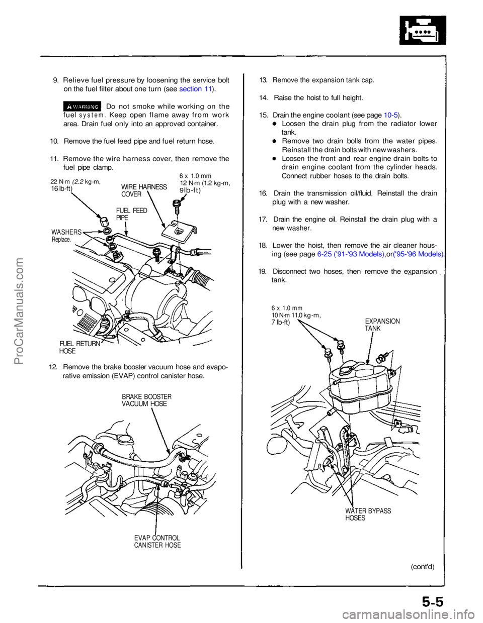
9. Relieve fuel pressure by loosening the service bolt
on the fuel filter about one turn (see section 11).
Do not smoke while working on the
fuel
system.
Keep open flame away from work
area. Drain fuel only into an approved container.
10. Remove the fuel feed pipe and fuel return hose.
11. Remove the wire harness cover, then remove the fuel pipe clamp.
22 N·m
(2.2 kg-m,
16 Ib-ft)
WIRE HARNESS
COVER
6 x 1.0 mm
12 N·m
(1.2 kg-m,
9 lb-ft)
FUEL FEED
PIPE
WASHERS
Replace.
FUEL RETURN
HOSE
12. Remove the brake booster vacuum hose and evapo- rative emission (EVAP) control canister hose.
BRAKE BOOSTER
VACUUM HOSE
EVAP CONTROL
CANISTER HOSE
13. Remove the expansion tank cap.
14. Raise the hoist to full height.
15. Drain the engine coolant (see page
10-5).
Loosen the drain plug from the radiator lower
tank. Remove two drain bolls from the water pipes.
Reinstall the drain bolts with new washers.
Loosen the front and rear engine drain bolts to
drain engine coolant from the cylinder heads.
Connect rubber hoses to the drain bolts.
16. Drain the transmission oil/fluid. Reinstall the drain plug with a new washer.
17. Drain the engine oil. Reinstall the drain plug with a
new washer.
18. Lower the hoist, then remove the air cleaner hous-
ing (see page 6-25 ('91-'93 Mode ls),or('95-'96 Models).
19. Disconnect two hoses, then remove the expansion
tank.
6 x 1.0 mm
10 N·m
11.0 kg-m,
7 lb-ft)
EXPANSION
TANK
WATER BYPASS
HOSES
(cont'd)ProCarManuals.com
Page 378 of 1640
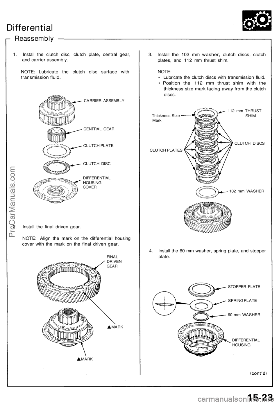
Differential
Reassembl y
1. Instal l th e clutc h disc , clutc h plate , centra l gear ,
an d carrie r assembly .
NOTE : Lubricat e th e clutc h dis c surfac e wit h
transmissio n fluid .
CARRIE R ASSEMBL Y
CENTRAL GEA R
CLUTC H PLAT E
CLUTC H DIS C
DIFFERENTIA LHOUSINGCOVER
2. Instal l th e fina l drive n gear .
NOTE : Alig n th e mar k o n th e differentia l housin g
cove r wit h th e mar k o n th e fina l drive n gear .
FINALDRIVE NGEAR
MAR K
MAR K
3. Instal l th e 10 2 m m washer , clutc h discs , clutc h
plates , an d 11 2 m m thrus t shim .
NOTE :
• Lubricat e th e clutc h disc s wit h transmissio n fluid .
• Positio n th e 11 2 m m thrus t shi m wit h th e
thicknes s siz e mar k facin g awa y fro m th e clutc h
discs .
Thicknes s Siz eMar k
CLUTC H PLATE S 11
2 m m THRUS T
SHIM
CLUTC H DISC S
10 2 m m WASHE R
4. Instal l th e 6 0 m m washer , sprin g plate , an d stoppe r
plate .
STOPPE R PLAT E
SPRING PLAT E
6 0 m m WASHE R
DIFFERENTIA LHOUSING
ProCarManuals.com
Page 498 of 1640
Reassembly
CAUTION:
• Befor e reassembling , chec k tha t al l part s ar e fre e o f
dus t an d othe r foreig n particles .
• Replac e part s wit h ne w one s wheneve r specifie d t o
do so .
• Us e onl y clea n DOT 3 o r 4 brak e fluid .
• Mak e sur e n o dir t o r othe r foreig n matte r i s allowe d
t o contaminat e th e brak e fluid .
• D o no t spil l brak e flui d o n th e car ; i t ma y damag e th e
paint ; i f brak e flui d doe s contac t th e paint , was h i t
of f immediatel y wit h water .
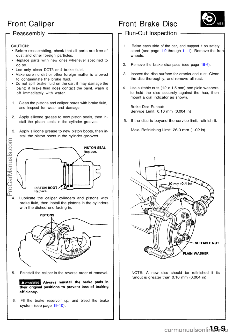
1. Clea n th e piston s an d calipe r bore s wit h brak e fluid ,
and inspec t fo r wea r an d damage .
2. Appl y silicon e greas e t o ne w pisto n seals , the n in -
stal l th e pisto n seal s i n th e cylinde r grooves .
3. Appl y silicon e greas e t o ne w pisto n boots , the n in -
stal l th e pisto n boot s in th e cylinde r grooves .
4. Lubricat e th e calipe r cylinder s an d piston s wit h
brak e fluid , the n instal l th e piston s i n th e cylinder s
with th e dishe d en d facin g in .
5. Reinstal l th e calipe r i n th e revers e orde r o f removal .
6 . Fil l th e brak e reservoi r up , an d blee d th e brak e
system (se e pag e 19-10 ).
NOTE : A ne w dis c shoul d b e refinishe d i f it s
runou t i s greate r tha n 0.1 0 m m (0.00 4 in) .
Fron t Brak e Dis c
Run-Ou t Inspectio n
1. Rais e eac h sid e o f th e car , an d suppor t i t o n safet y
stand (se e pag e 1-9 throug h 1-11 ). Remov e th e fron t
wheels .
2. Remov e th e brak e dis c pad s (se e pag e 19-6 ).
3 . Inspec t th e dis c surfac e fo r crack s an d rust . Clea n
the dis c thoroughly , an d remov e al l rust .
4. Us e suitabl e nut s (1 2 x 1. 5 mm ) an d plai n washer s
to hol d th e dis c securel y agains t th e hub , the n
moun t a dia l indicato r a s shown .
Brake Dis c Runout :
Service Limit : 0.1 0 m m (0.00 4 in )
5. I f th e dis c i s beyon d th e servic e limit , refinis h it .
Max . Refinishin g Limit : 26. 0 m m (1.0 2 in )
Front Caliper
ProCarManuals.com
Page 512 of 1640
Reassembly
CAUTION:
• Mak e sur e al l part s ar e clea n befor e reassembly .
• Us e onl y ne w replacemen t parts .
• Us e onl y clea n DOT 3 o r 4 brak e fluid .
• D o no t allo w dir t o r othe r foreig n matte r t o con -
taminat e th e brak e fluid .
• Avoi d spillin g brak e flui d o n painted , plasti c o r rubbe r
surface s a s i t ca n damag e th e finish . Was h spille d
brak e flui d of f immediatel y wit h clea n water .
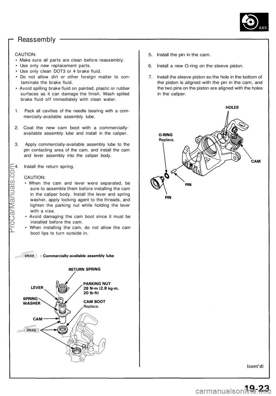
1 . Pac k al l cavitie s o f th e needl e bearin g wit h a com -
mercially-availabl e assembl y lube .
2. Coa t th e ne w ca m boo t wit h a commercially -
available assembl y lub e an d instal l i n th e caliper .
3 . Appl y commercially-availabl e assembl y lub e t o th e
pi n contactin g are a o f th e cam , an d instal l th e ca m
an d leve r assembl y int o th e calipe r body .
4. Instal l th e retur n spring .
CAUTION :
• Whe n th e ca m an d leve r wer e separated , b e
sur e t o assembl e the m befor e installin g th e ca m
i n th e calipe r body . Instal l th e leve r an d sprin g
washer , appl y lockin g agen t t o th e threads , an d
tighte n th e parkin g nu t whil e holdin g th e leve r
wit h a vise .
• Avoi d damagin g th e ca m boo t sinc e i t mus t b e
installe d befor e th e cam .
• Whe n installin g th e cam , d o no t allo w th e ca m
boo t lip s t o tur n outsid e in .
5. Instal l th e pi n in th e cam .
6. Instal l a ne w O-rin g o n th e sleev e piston .
7. Instal l th e sleev e pisto n s o th e hol e in th e botto m of
the pisto n is aligne d wit h th e pi n in th e cam , an d
the tw o pin s o n th e pisto n ar e aligne d wit h th e hole s
in th e caliper .
ProCarManuals.com
Page 538 of 1640
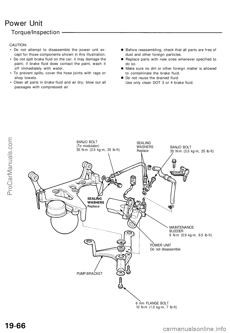
Power Uni t
Torque/Inspectio n
CAUTION:
• D o no t attemp t t o disassembl e th e powe r uni t ex -
cep t fo r thos e component s show n in thi s illustration .
• D o no t spil l brak e flui d o n th e car ; i t ma y damag e th e
paint ; i f brak e flui d doe s contac t th e paint , was h i t
of f immediatel y wit h water .
• T o preven t spills , cove r th e hos e joint s wit h rag s o r
sho p towels .
• Clea n al l part s i n brak e flui d an d ai r dry ; blo w ou t al l
passage s wit h compresse d air . Befor
e reassembling , chec k tha t al l part s ar e fre e o f
dus t an d othe r foreig n particles .
Replac e part s wit h ne w one s wheneve r specifie d t o
do so .
Mak e sur e n o dir t o r othe r foreig n matte r i s allowe d
t o contaminat e th e brak e fluid .
D o no t reus e th e draine d fluid .
Us e onl y clea n DO T 3 o r 4 brak e fluid .
BANJ O BOL T(To modulator )35 N- m (3. 5 kg-m , 2 5 Ib-ft )
SEALIN GWASHER SReplaceBANJO BOL T35 N- m (3. 5 kg-m , 2 5 Ib-ft )
MAINTENANC EBLEEDER9 N- m (0. 9 kg-m , 6. 5 Ib-ft )
POWE R UNI TDo no t disassembl e
PUMP BRACKE T
6 m m FLANG E BOL T10 N- m (1. 0 kg-m , 7 Ib-ft )
ProCarManuals.com
Page 539 of 1640
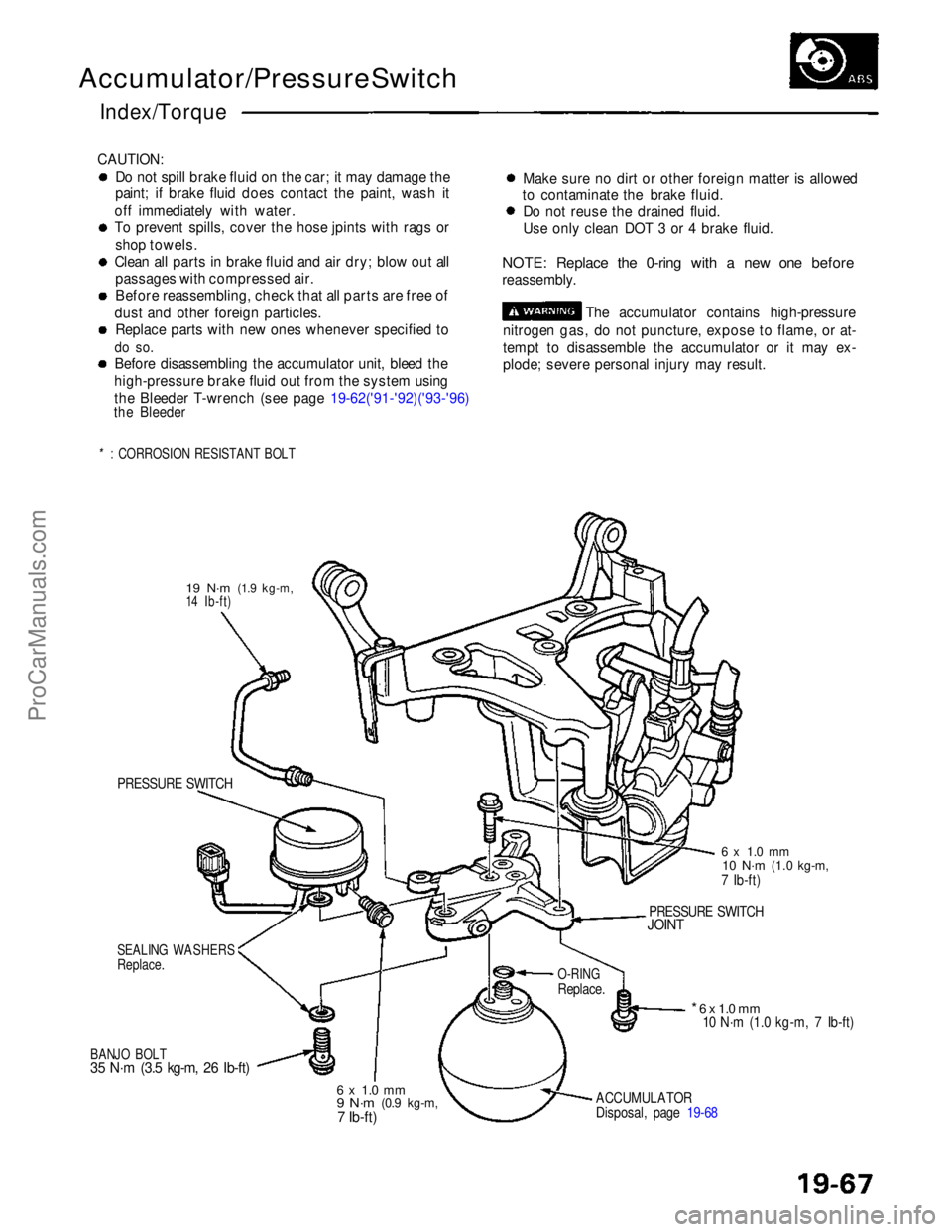
Accumulator/Pressure Switch
Index/Torque
CAUTION: Do not spill brake fluid on the car; it may damage the
paint; if brake fluid does contact the paint, wash it
off immediately with water.
To prevent spills, cover the hose jpints with rags or shop towels.
Clean all parts in brake fluid and air dry; blow out all passages with compressed air.
Before reassembling, check that all parts are free of
dust and other foreign particles. Replace parts with new ones whenever specified to
do so.
Before disassembling the accumulator unit, bleed the
high-pressure brake fluid out from the system using
the Bleeder T-wrench (see page 19-62('91-'92)('93-'96)
the Bleeder
*: CORROSION RESISTANT BOLT
Make sure no dirt or other foreign matter is allowed
to contaminate the brake fluid. Do not reuse the drained fluid.
Use only clean DOT 3 or 4 brake fluid.
NOTE: Replace the 0-ring with a new one before
reassembly. The accumulator contains high-pressure
nitrogen gas, do not puncture, expose to flame, or at-
tempt to disassemble the accumulator or it may ex-
plode; severe personal injury may result.
19 N·m
(1.9 kg-m,
14 Ib-ft)
PRESSURE SWITCH
SEALING WASHERS
Replace.
BANJO BOLT
35 N·m (3.5 kg-m, 26 Ib-ft)
6 x 1.0 mm
9 N·m
(0.9 kg-m,7 Ib-ft)
ACCUMULATOR
Disposal, page 19-68
* 6 x 1.0 mm
10 N·m (1.0 kg-m, 7 Ib-ft)
O-RING
Replace.
PRESSURE SWITCH
JOINT
6 x 1.0 mm
10 N·m
(1.0 kg-m,
7 Ib-ft)ProCarManuals.com
Page 926 of 1640
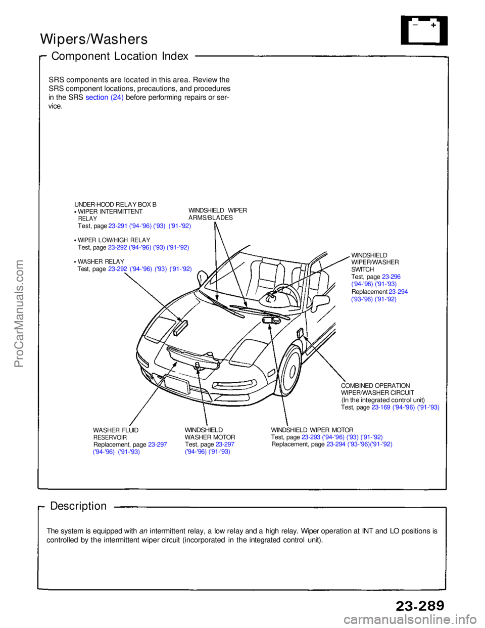
Wipers/Washers
Component Location Index
SRS components are located in this area. Review theSRS component locations, precautions, and procedures
in the SRS section (24) before performing repairs or ser-
vice.
UNDER-HOOD RELAY BOX BWIPER INTERMITTENT
RELAY
Test, page 23-291 ('94-'96) ('93) ('91-'92)
WIPER LOW/HIGH RELAY
Test, page 23-292 ('94-'96) ('93) ('91-'92)
WASHER RELAY
Test, page 23-292 ('94-'96) ('93) ('91-'92) WINDSHIELD WIPER
ARMS/BLADES
WASHER FLUID
RESERVOIR
Replacement, page 23-297
('94-'96) ('91-'93)
WINDSHIELD
WASHER MOTOR
Test, page 23-297
('94-'96) ('91-'93) WINDSHIELD WIPER MOTOR
Test, page 23-293 ('94-'96) ('93) ('91-'92)
Replacement, page 23-294 ('93-'96)('91-'92) COMBINED OPERATION
WIPER/WASHER CIRCUIT
(In the integrated control unit)
Test, page 23-169 ('94-'96) ('91-'93)
Description
The system is equipped with an intermittent relay, a low relay and a high relay. Wiper operation at INT and LO positions is
controlled by the intermittent wiper circuit (incorporated in the integrated control unit). WINDSHIELD
WIPER/WASHER
SWITCH
Test, page 23-296
('94-'96) ('91-'93)
Replacement 23-294
('93-'96) ('91-'92)ProCarManuals.com
Page 932 of 1640
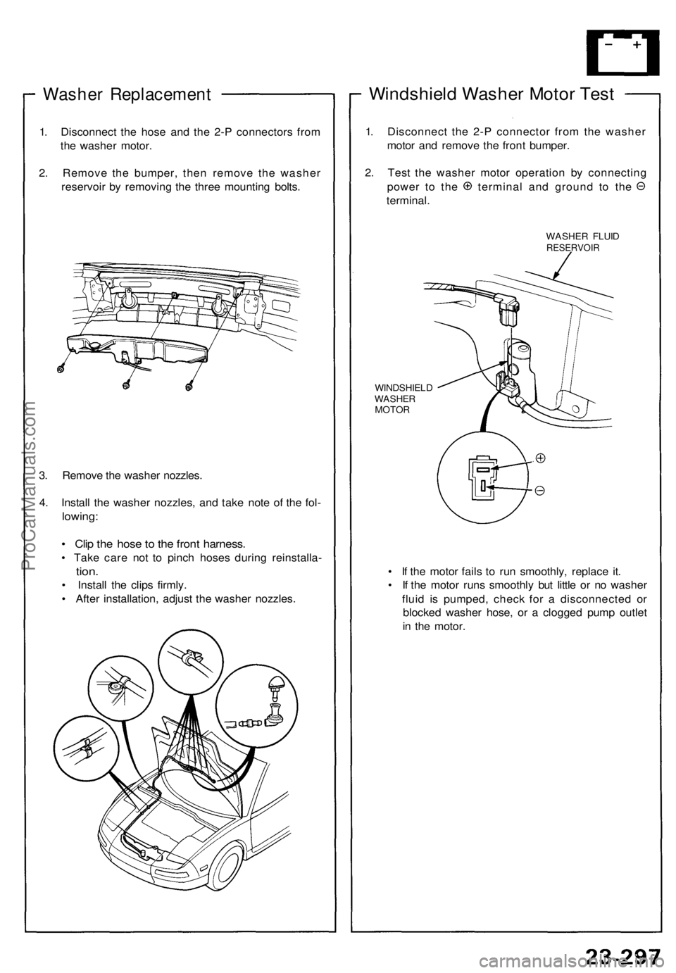
Washer Replacement
1. Disconnect the hose and the 2-P connectors from
the washer motor.
2. Remove the bumper, then remove the washer
reservoir by removing the three mounting bolts.
3. Remove the washer nozzles.
4. Install the washer nozzles, and take note of the fol-
lowing:
• Clip the hose to the front harness.
• Take care not to pinch hoses during reinstalla-
tion.
• Install the clips firmly.
• After installation, adjust the washer nozzles.
Windshield Washer Motor Test
1. Disconnect the 2-P connector from the washer
motor and remove the front bumper.
2. Test the washer motor operation by connecting
power to the terminal and ground to the
terminal.
WASHER FLUID
RESERVOIR
WINDSHIELD
WASHER
MOTOR
• If the motor fails to run smoothly, replace it.
• If the motor runs smoothly but little or no washer
fluid is pumped, check for a disconnected or
blocked washer hose, or a clogged pump outlet
in the motor.ProCarManuals.com
Page 986 of 1640
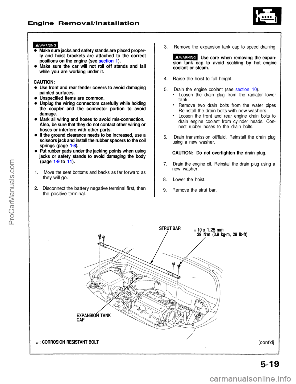
Engine Removal/Installation
Make sure jacks and safety stands are placed proper-ly and hoist brackets are attached to the correct
positions on the engine (see section 1).
Make sure the car will not roll off stands and fall
while you are working under it. 3. Remove the expansion tank cap to speed draining.
Use care when removing the expan-
sion tank cap to avoid scalding by hot engine
coolant or steam.
4. Raise the hoist to full height.
5. Drain the engine coolant (see section 10).
STRUT BAR
10 x
1.25
mm
39 N.m (3.9 kg-m, 28 Ib-ft)
EXPANSION TANK
CAP
: CORROSION RESISTANT BOLT
(cont'dj
1. Move the seat bottoms and backs as far forward as
they will go.
2. Disconnect the battery negative terminal first, then
the positive terminal.
Loosen the drain plug from the radiator lower
tank.
Remove two drain bolts from the water pipes
Reinstall the drain bolts with new washers.
Loosen the front and rear engine drain bolts to
drain engine coolant from cylinder heads. Con-
nect rubber hoses to the drain bolts.
6. Drain transmission oil/fluid. Reinstall the drain plug using a new washer.
CAUTION: Do not overtighten the drain plug.
7. Drain the engine oil. Reinstall the drain plug using a new washer.
8. Lower the hoist.
9. Remove the strut bar.
CAUTION:
Use front and rear fender covers to avoid damaging
painted surfaces.
Unspecified items are common.Unplug the wiring connectors carefully while holding
the coupler and the connector portion to avoid damage.
Mark all wiring and hoses to avoid mis-connection.
Also, be sure that they do not contact other wiring or hoses or interfere with other parts.
If the ground clearance needs to be increased, use a
scissors jack and install the rubber spacers to the coil
springs (page 1-8).
Put rubber pads under the jacking points when using
jacks or safety stands to avoid damaging the body (page 1-9 to 11).ProCarManuals.com
Page 1224 of 1640
Fluid Level
Checking/Changing
Checking
NOTE: Check the fluid level with the engine at nor-
mal operating temperature (the cooling fan comes
on).
1. Park the car on level ground. Turn off the engine.
2. Remove the dipstick (yellow loop) from the
transmission, and wipe it with a clean cloth.
NOTE: Check the fluid level for to 90 seconds
from 60 seconds after the engine had shut off.
3. Insert the dipstick into the transmission.
4. Remove the dipstick, and check the fluid level. It
should be between the upper and lower marks.
5. If the level is below the lower mark, add fluid into
the tube to bring it to the upper mark. Use Honda
Premium Formula Automatic Transmission Fluid or
an equivalent DEXRON® II Automatic Transmission
Fluid (ATF) only.
6. Insert the dipstick back into the transmission.
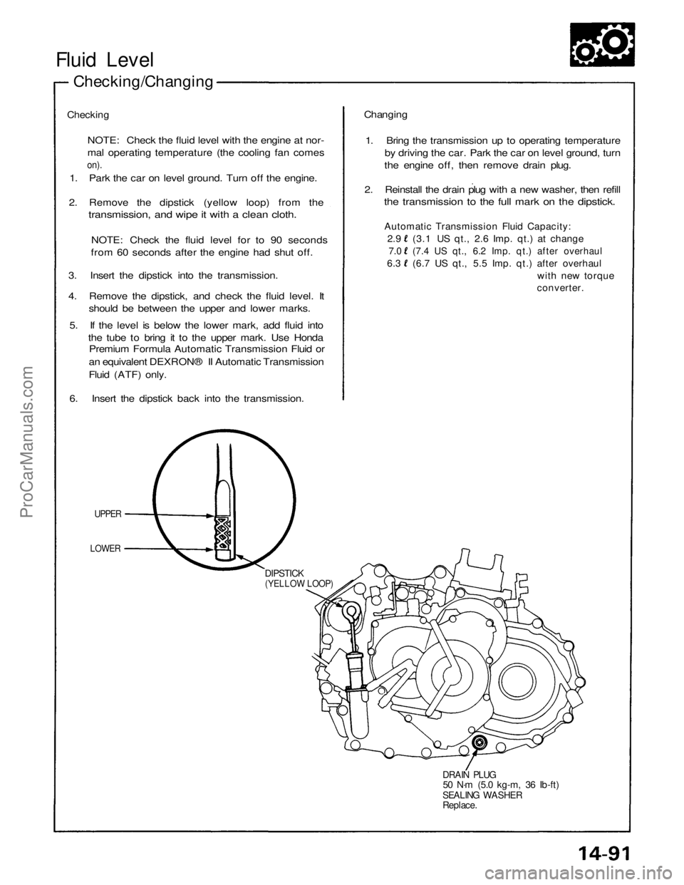
UPPER
LOWER
DIPSTICK
(YELLOW LOOP)
DRAIN PLUG
50 N·m (5.0 kg-m, 36 Ib-ft)
SEALING WASHER
Replace.
Changing
1. Bring the transmission up to operating temperature
by driving the car. Park the car on level ground, turn
the engine off, then remove drain plug.
2. Reinstall the drain plug with a new washer, then refill
the transmission to the full mark on the dipstick.
Automatic Transmission Fluid Capacity:
2.9 (3.1 US qt., 2.6 Imp. qt.) at change
7.0 (7.4 US qt., 6.2 Imp. qt.) after overhaul
6.3 (6.7 US qt., 5.5 Imp. qt.) after overhaul
with new torque
converter.ProCarManuals.com