service indicator ACURA NSX 1991 Service Repair Manual
[x] Cancel search | Manufacturer: ACURA, Model Year: 1991, Model line: NSX, Model: ACURA NSX 1991Pages: 1640, PDF Size: 60.48 MB
Page 115 of 1640
Valve Guides
Valve Movement
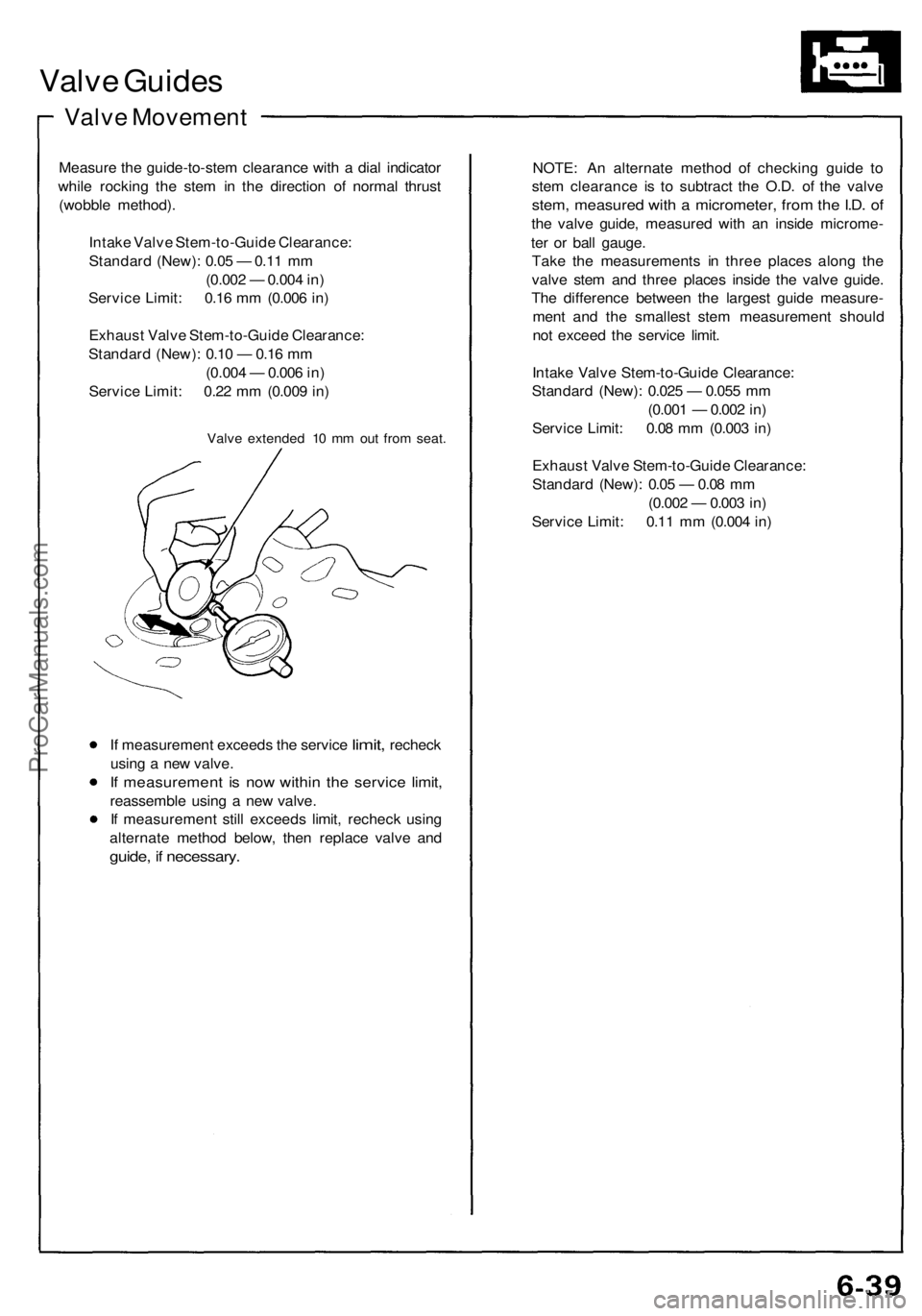
Measure the guide-to-stem clearance with a dial indicator
while rocking the stem in the direction of normal thrust
(wobble method).
Intake Valve Stem-to-Guide Clearance:
Standard (New): 0.05 — 0.11 mm
(0.002 — 0.004 in)
Service Limit: 0.16 mm (0.006 in)
Exhaust Valve Stem-to-Guide Clearance:
Standard (New): 0.10 — 0.16 mm
(0.004 — 0.006 in)
Service Limit: 0.22 mm (0.009 in)
Valve extended 10 mm out from seat.
If
measurement exceeds
the
service
limit,
recheck
using a new valve.
If measurement is now within the service limit,
reassemble using a new valve.
If measurement still exceeds limit, recheck using
alternate method below, then replace valve and
guide, if necessary.
NOTE: An alternate method of checking guide to
stem clearance is to subtract the O.D. of the valve
stem, measured with a micrometer, from the I.D. of
the valve guide, measured with an inside microme-
ter or ball gauge.
Take the measurements in three places along the
valve stem and three places inside the valve guide.
The difference between the largest guide measure-
ment and the smallest stem measurement should
not exceed the service limit.
Intake Valve Stem-to-Guide Clearance:
Standard (New): 0.025 — 0.055 mm
(0.001 — 0.002 in)
Service Limit: 0.08 mm (0.003 in)
Exhaust Valve Stem-to-Guide Clearance:
Standard (New): 0.05 — 0.08 mm
(0.002 — 0.003 in)
Service Limit: 0.11 mm (0.004 in)ProCarManuals.com
Page 296 of 1640
Mid Plate Guide
Replacement (cont'd)
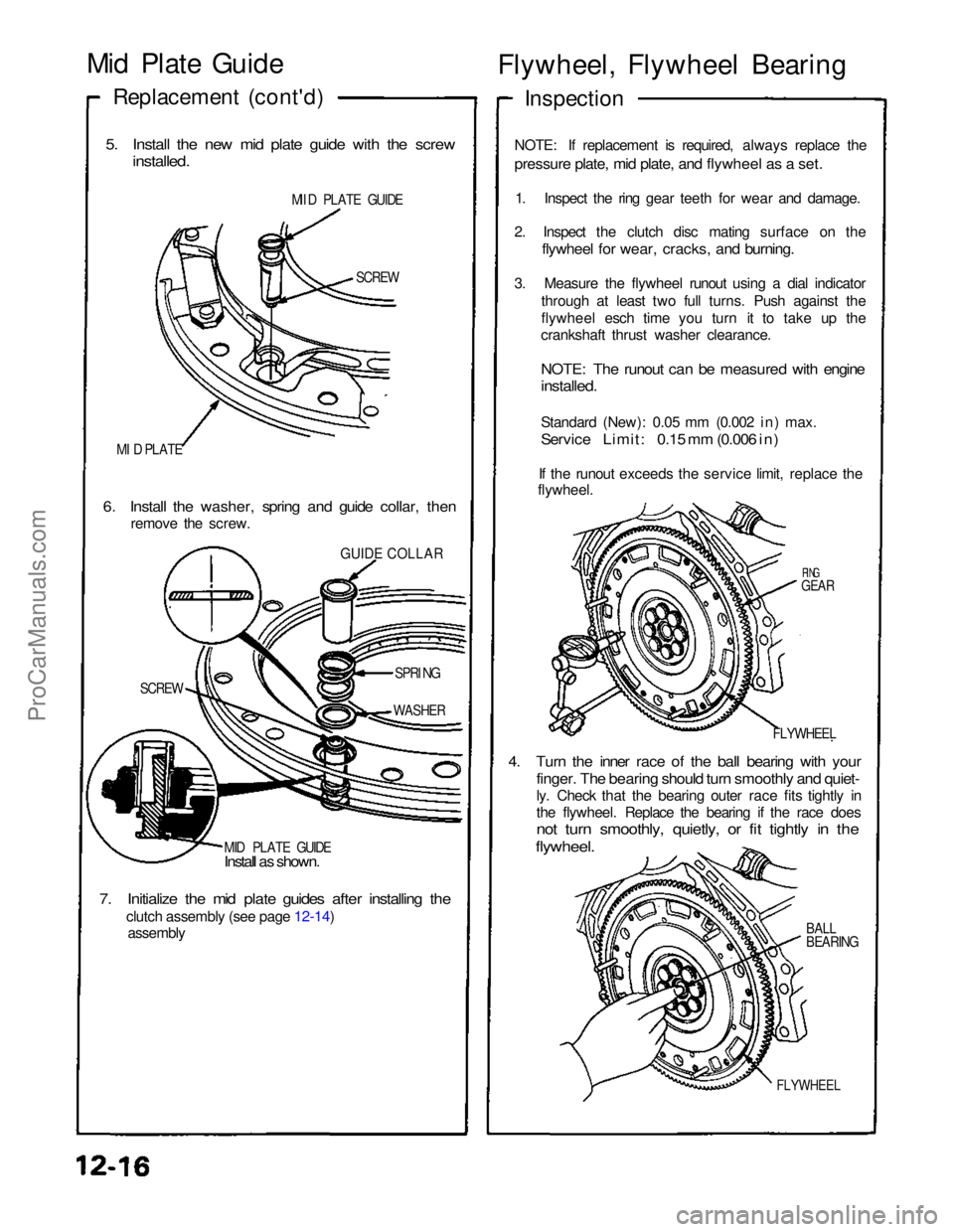
5. Install the new mid plate guide with the screw
installed.
MII D PLATE GUIDE
SCREW
MI D PLATE
6. Install the washer, spring and guide collar, then
remove the screw.
GUIDE COLLAR
SCREW SPRI
NG
WASHER
MID PLATE GUIDE
Install as shown.
7. Initialize the mid plate guides after installing the
clutch assembly (see page 12-14)
assembly Flywheel, Flywheel Bearing
Inspection
NOTE: If replacement is required, always replace the
pressure plate, mid plate, and flywheel as a set.
1. Inspect the ring gear teeth for wear and damage.
2. Inspect the clutch disc mating surface on the
flywheel for wear, cracks, and burning.
3. Measure the flywheel runout using a dial indicator through at least two full turns. Push against the
flywheel esch time you turn it to take up the
crankshaft thrust washer clearance.
NOTE: The runout can be measured with engine
installed.
Standard (New): 0.05 mm (0.002 in) max.
Service Limit: 0.15 mm (0.006 in)
If the runout exceeds the service limit, replace the
flywheel.
RING
GEAR
FLYWHEEL
4. Turn the inner race of the ball bearing with your
finger. The bearing should turn smoothly and quiet-
ly. Check that the bearing outer race fits tightly in
the flywheel. Replace the bearing if the race does
not turn smoothly, quietly, or fit tightly in the
flywheel.
BALL
BEARING
FLYWHEELProCarManuals.com
Page 422 of 1640
Diagnostic Trouble Code (DTC) Indication
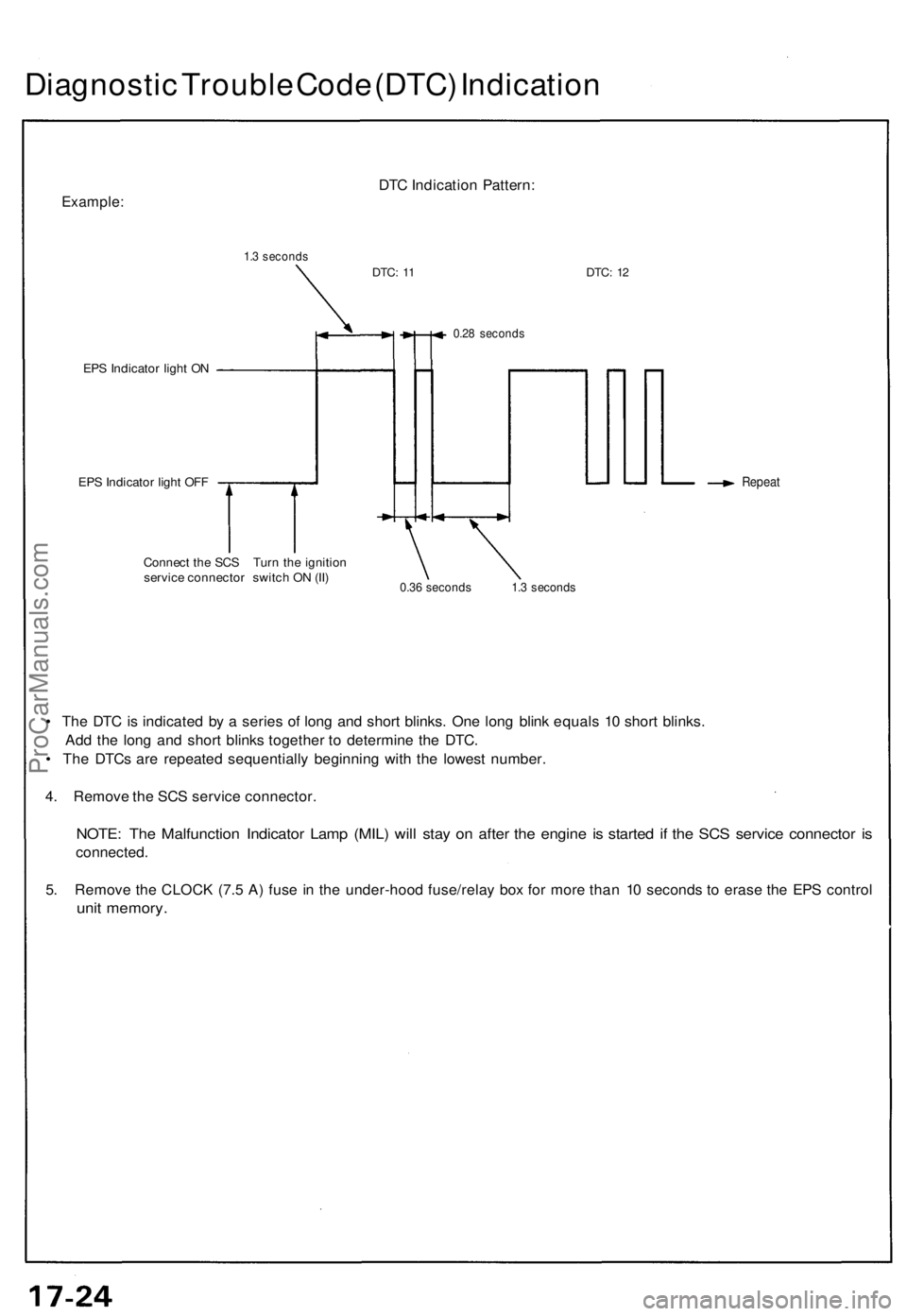
Example:
1.3 seconds
DTC Indication Pattern:
DTC:
11
DTC:
12
EPS Indicator light ON
EPS Indicator light OFF
0.28 seconds
Repeat
Connect the SCS Turn the ignition
service connector switch ON (II)
0.36 seconds 1.3 seconds
• The DTC is indicated by a series of long and short blinks. One long blink equals 10 short blinks.
Add the long and short blinks together to determine the DTC.
• The DTCs are repeated sequentially beginning with the lowest number.
4. Remove the SCS service connector.
NOTE: The Malfunction Indicator Lamp (MIL) will stay on after the engine is started if the SCS service connector is
connected.
5. Remove the CLOCK (7.5 A) fuse in the under-hood fuse/relay box for more than 10 seconds to erase the EPS control
unit memory.ProCarManuals.com
Page 531 of 1640
Diagnostic Trouble Code (DTC):
1. Stop the engine.
2. Disconnect the service check connector from the connector cover located under the glove box.
Connect the two terminals of the service check connector with a jumper wire.
3. Turn the ignition switch on, but do not start the engine.
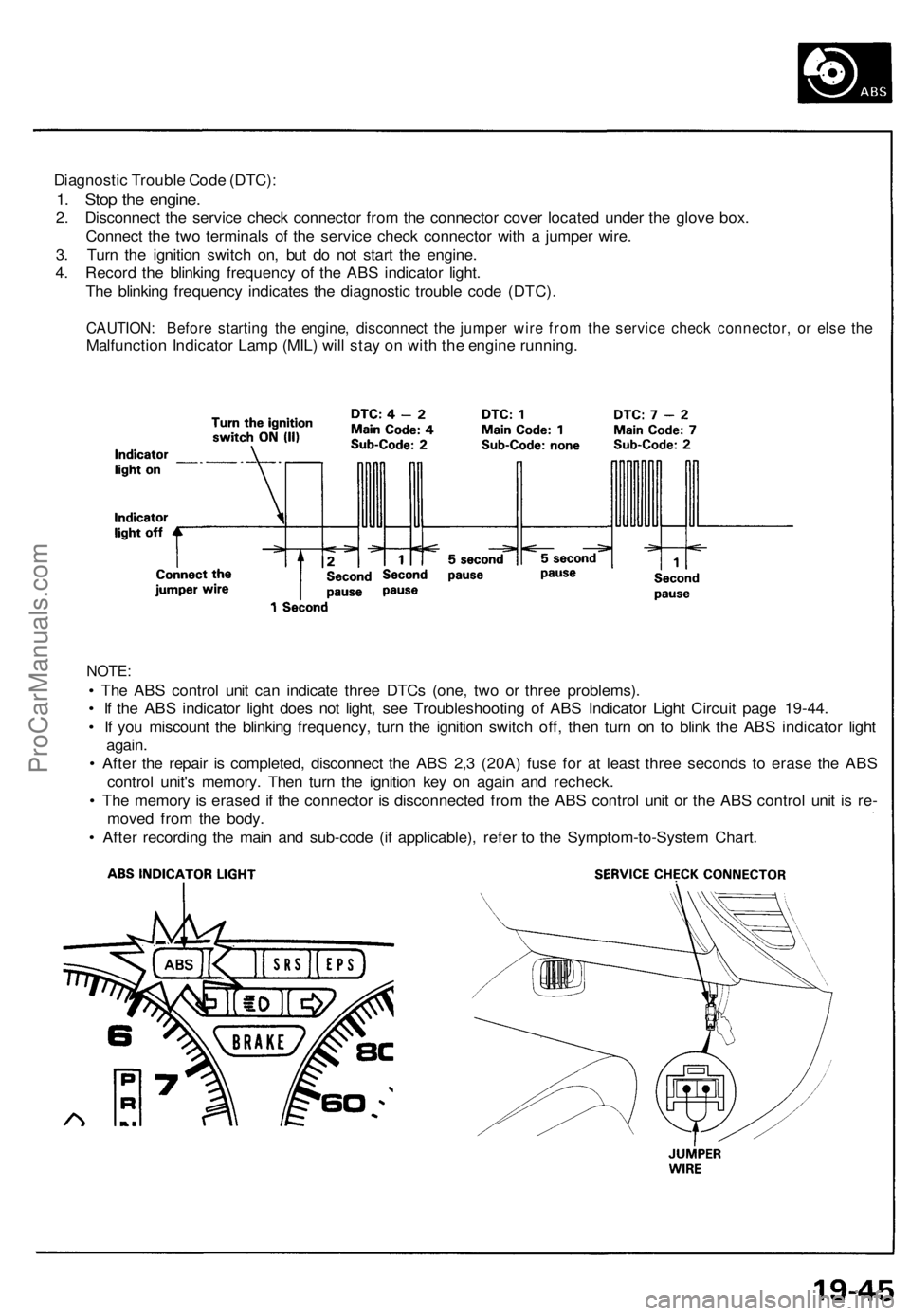
4. Record the blinking frequency of the ABS indicator light.
The blinking frequency indicates the diagnostic trouble code (DTC).
CAUTION: Before starting the engine, disconnect the jumper wire from the service check connector, or else the
Malfunction Indicator Lamp (MIL) will stay on with the engine running.
NOTE:
• The ABS control unit can indicate three DTCs (one, two or three problems).
• If the ABS indicator light does not light, see Troubleshooting of ABS Indicator Light Circuit page 19-44.
• If you miscount the blinking frequency, turn the ignition switch off, then turn on to blink the ABS indicator light
again.
• After the repair is completed, disconnect the ABS 2,3 (20A) fuse for at least three seconds to erase the ABS
control unit's memory. Then turn the ignition key on again and recheck.
• The memory is erased if the connector is disconnected from the ABS control unit or the ABS control unit is re-
moved from the body.
• After recording the main and sub-code (if applicable), refer to the Symptom-to-System Chart.ProCarManuals.com
Page 754 of 1640
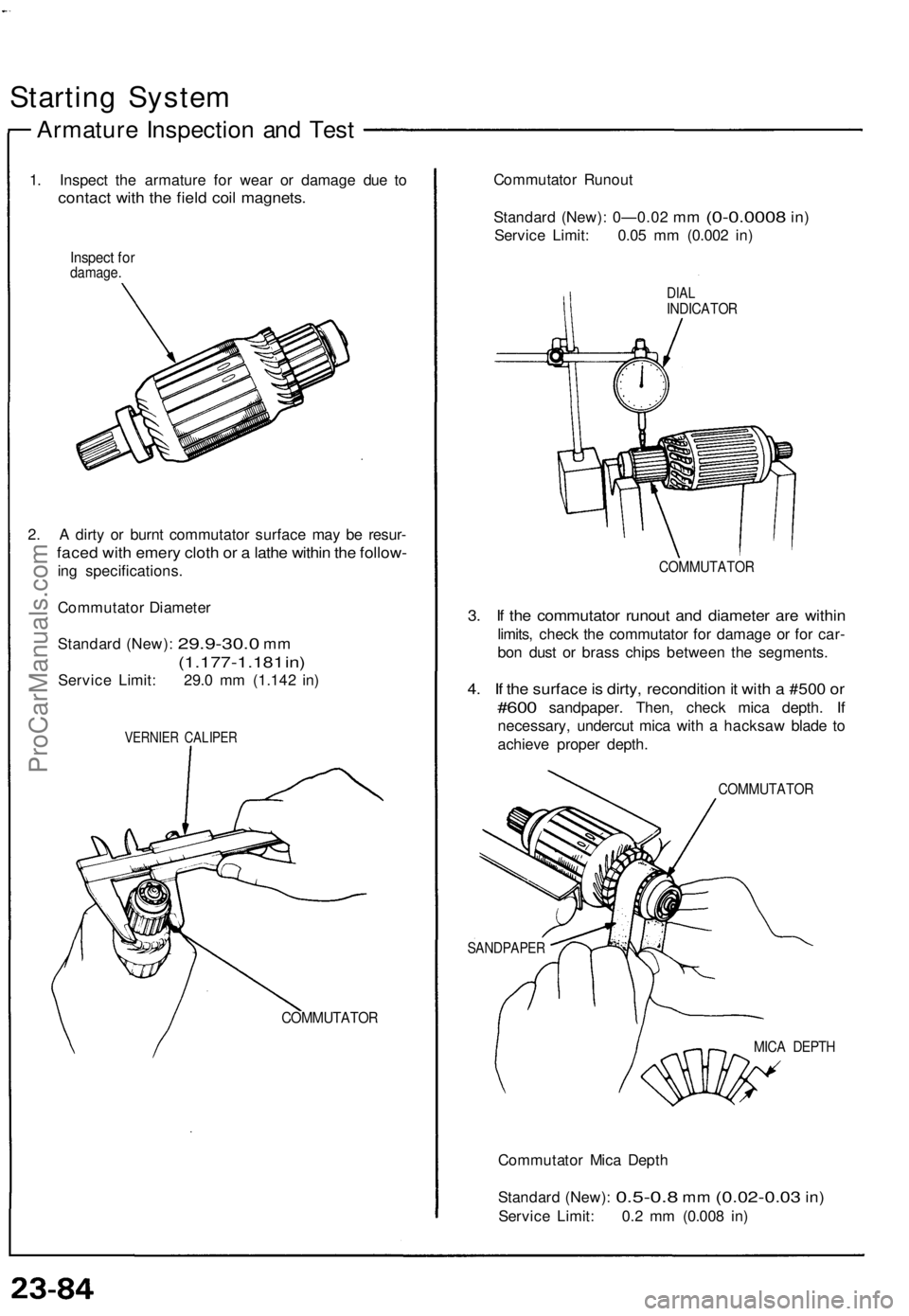
Starting System
Armature Inspection and Test
1. Inspect the armature for wear or damage due to
contact with the field coil magnets.
Inspect for
damage.
2. A dirty or burnt commutator surface may be resur-
faced with emery cloth or a lathe within the follow-
ing specifications.
Commutator Diameter
Standard (New):
29.9-30.0
mm
(1.177-1.181 in)
Service Limit: 29.0 mm (1.142 in)
VERNIER CALIPER
COMMUTATOR
Commutator Runout
Standard (New): 0—0.02
mm
(0-0.0008
in)
Service Limit: 0.05 mm (0.002 in)
DIAL
INDICATOR
COMMUTATOR
3. If the commutator runout and diameter are within
limits, check the commutator for damage or for car-
bon dust or brass chips between the segments.
4. If the surface is dirty, recondition it with a #500 or
#600
sandpaper. Then, check mica depth.
If
necessary, undercut mica with a hacksaw blade to
achieve proper depth.
COMMUTATOR
SANDPAPER
MICA DEPTH
Commutator Mica Depth
Standard (New):
0.5-0.8
mm
(0.02-0.03
in)
Service Limit: 0.2 mm (0.008 in)ProCarManuals.com
Page 786 of 1640
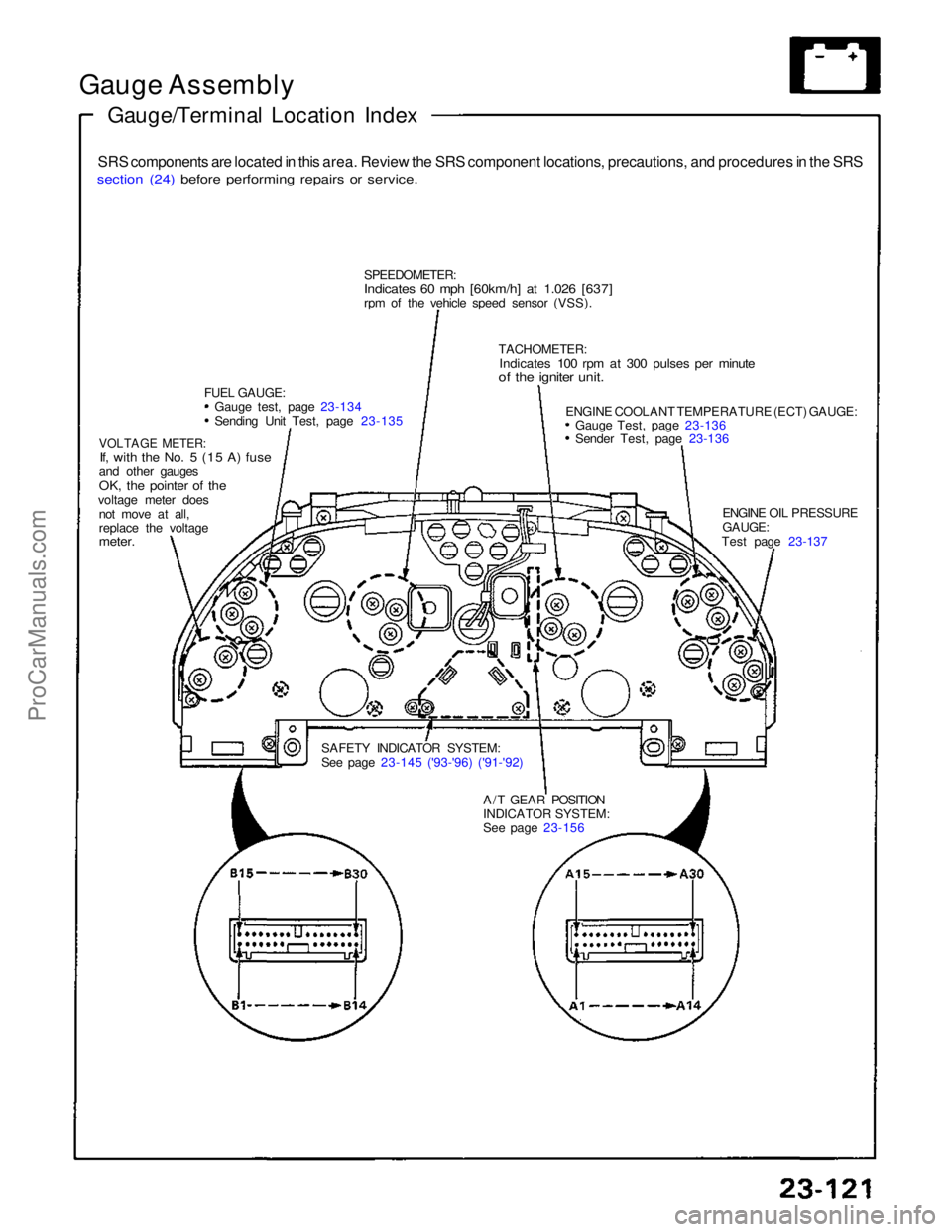
Gauge Assembly
Gauge/Terminal Location Index
SRS components are located in this area. Review the SRS component locations, precautions, and procedures in the SRS
section (24) before performing repairs or service.
SPEEDOMETER:
Indicates 60 mph [60km/h] at 1.026 [637]
rpm of the vehicle speed sensor (VSS).
FUEL GAUGE: Gauge test, page 23-134 Sending Unit Test, page 23-135
VOLTAGE METER:
If, with the No. 5 (15 A) fuse
and other gauges
OK, the pointer of the
voltage meter does not move at all,
replace the voltage
meter.
SAFETY INDICATOR SYSTEM:
See page 23-145 ('93-'96) ('91-'92)A/T GEAR POSITION
INDICATOR SYSTEM:
See page 23-156 ENGINE OIL PRESSURE
GAUGE:
Test page 23-137
ENGINE COOLANT TEMPERATURE (ECT) GAUGE:
Gauge Test, page 23-136 Sender Test, page 23-136
TACHOMETER:
Indicates 100 rpm at 300 pulses per minute
of the igniter unit.ProCarManuals.com
Page 805 of 1640
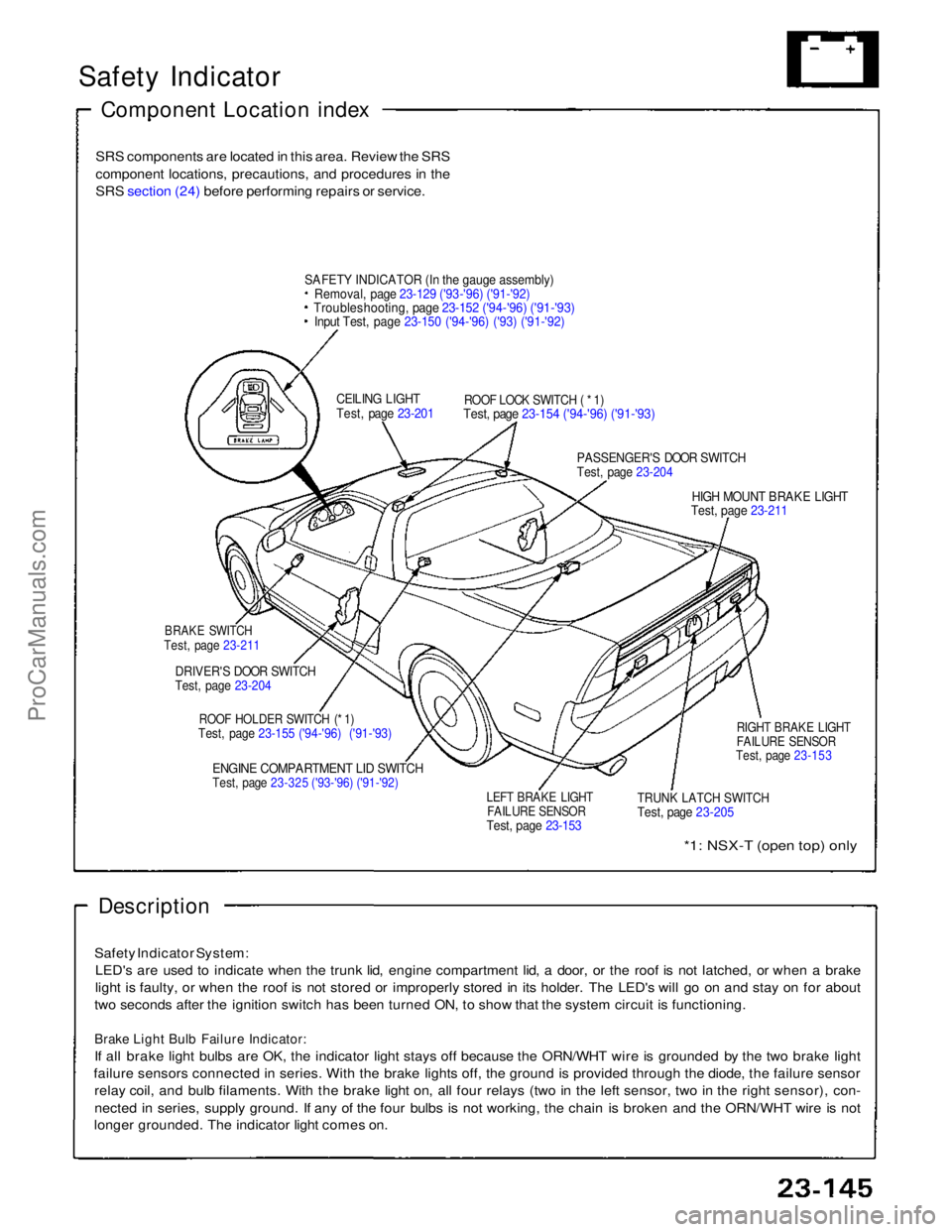
Safety Indicator
Component Location index
SRS components are located in this area. Review the SRS
component locations, precautions, and procedures in the
SRS section (24) before performing repairs or service.
SAFET
Y
INDICATOR (In the gauge assembly)
Removal, page 23-129 ('93-'96) ('91-'92)
Troubleshooting, page 23-152 ('94-'96) ('91-'93)
Input Test, page 23-150 ('94-'96) ('93) ('91-'92)
CEILING LIGHT
Test, page 23-201
ROOF LOCK SWITCH ( * 1)
Test, page 23-154 ('94-'96) ('91-'93)
PASSENGER'S DOOR SWITCH
Test, page 23-204
HIGH MOUNT BRAKE LIGHT
Test, page 23-211
BRAKE SWITCH
Test, page 23-211
DRIVER'S DOOR SWITCH
Test, page 23-204
ROOF HOLDER SWITCH (* 1)
Test, page 23-155 ('94-'96) ('91-'93)
ENGINE COMPARTMENT LID SWITCH
Test, page 23-325 ('93-'96) ('91-'92)
LEFT BRAKE LIGHT
FAILURE SENSOR
Test, page 23-153
TRUNK LATCH SWITCH
Test, page 23-205
RIGHT BRAKE LIGHT
FAILURE SENSOR
Test, page 23-153
*1: NSX-T (open top) only
Description
Safety Indicator System: LED's are used to indicate when the trunk lid, engine compartment lid, a door, or the roof is not latched, or when a brake
light is faulty, or when the roof is not stored or improperly stored in its holder. The LED's will go on and stay on for about
two seconds after the ignition switch has been turned ON, to show that the system circuit is functioning.
Brake Light Bulb Failure Indicator:
If all brake light bulbs are OK, the indicator light stays off because the ORN/WHT wire is grounded by the two brake light
failure sensors connected in series. With the brake lights off, the ground is provided through the diode, the failure sensor relay coil, and bulb filaments. With the brake light on, all four relays (two in the left sensor, two in the right sensor), con-
nected in series, supply ground. If any of the four bulbs is not working, the chain is broken and the ORN/WHT wire is not
longer grounded. The indicator light comes on.ProCarManuals.com
Page 806 of 1640
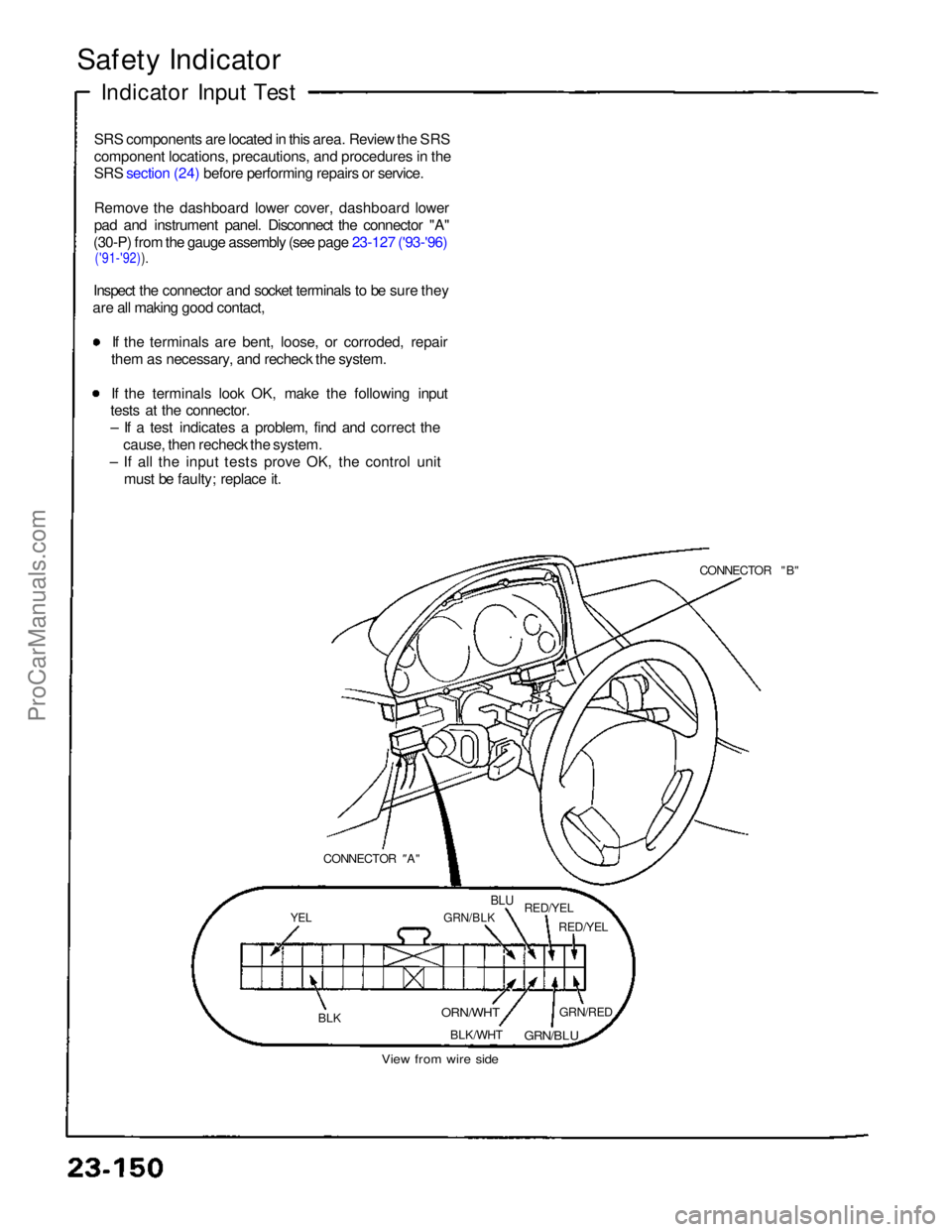
Safety Indicator
Indicator Input Test
SRS components are located in this area. Review the SRS
component locations, precautions, and procedures in the
SRS section (24) before performing repairs or service.
Remove the dashboard lower cover, dashboard lower
pad and instrument panel. Disconnect the connector "A"
(30-P) from the gauge assembly (see page 23-127 ('93-'96)
('91-'92)).
Inspect the connector and socket terminals to be sure they
are all making good contact,
If the terminals are bent, loose, or corroded, repair
them as necessary, and recheck the system. If the terminals look OK, make the following input
tests at the connector.
– If a test indicates a problem, find and correct the
cause, then recheck the system.
– If all the input tests prove OK, the control unit must be faulty; replace it.
CONNECTOR "B"
CONNECTOR "
A"
YEL
GRN/BLK
BLU
RED/YEL
RED/YEL
BLK
ORN/WHT
BLK/WHT GRN/RED
GRN/BLU
View from wire sideProCarManuals.com
Page 862 of 1640
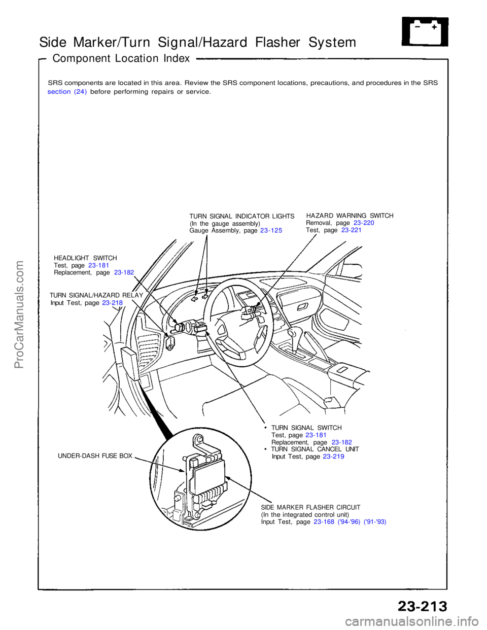
Side Marker/Turn Signal/Hazard Flasher System
Component Location Index
SRS components are located in this area. Review the SRS component locations, precautions, and procedures in the SRS
section (24) before performing repairs or service.
TURN SIGNAL INDICATOR LIGHTS(In the gauge assembly)
Gauge Assembly, page 23-125 HAZARD WARNING SWITCH
Removal, page 23-220
Test, page 23-221
HEADLIGHT SWITCH
Test, page 23-181
Replacement, page 23-182
TURN SIGNAL/HAZARD RELAY
Input Test, page 23-218
UNDER-DASH FUSE BOX TURN SIGNAL SWITCH
Test, page 23-181
Replacement, page 23-182 TURN SIGNAL CANCEL UNIT
Input Test, page 23-219
SIDE MARKER FLASHER CIRCUIT
(In the integrated control unit)
Input Test, page 23-168 ('94-'96) ('91-'93)ProCarManuals.com
Page 971 of 1640
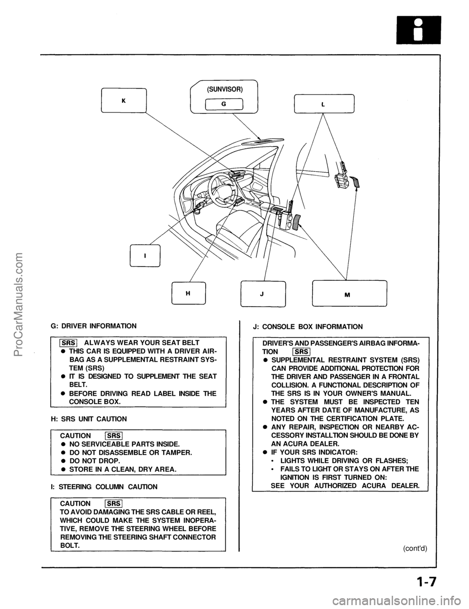
G: DRIVER INFORMATION
ALWAYS WEAR YOUR SEAT BELT
THIS CAR IS EQUIPPED WITH A DRIVER AIR- BAG AS A SUPPLEMENTAL RESTRAINT SYS-
TEM
(SRS) IT IS DESIGNED TO SUPPLEMENT THE SEAT
BELT.
BEFORE DRIVING READ LABEL INSIDE THE
CONSOLE BOX.
H: SRS UNIT CAUTION CAUTION NO SERVICEABLE PARTS INSIDE.
DO NOT DISASSEMBLE OR TAMPER.DO NOT DROP.
STORE IN A CLEAN, DRY AREA.
I: STEERING COLUMN CAUTION CAUTION
TO AVOID DAMAGING THE SRS CABLE OR REEL,
WHICH COULD MAKE THE SYSTEM INOPERA-
TIVE, REMOVE THE STEERING WHEEL BEFORE REMOVING THE STEERING SHAFT CONNECTOR
BOLT.
J: CONSOLE BOX INFORMATION
DRIVER'S AND PASSENGER'S AIRBAG INFORMA-
TION SUPPLEMENTAL RESTRAINT SYSTEM (SRS)
CAN PROVIDE ADDITIONAL PROTECTION FOR
THE DRIVER AND PASSENGER IN A FRONTAL
COLLISION. A FUNCTIONAL DESCRIPTION OF
THE SRS IS IN YOUR OWNER'S MANUAL.
THE SYSTEM MUST BE INSPECTED TEN YEARS AFTER DATE OF MANUFACTURE, AS
NOTED ON THE CERTIFICATION PLATE.
ANY REPAIR, INSPECTION OR NEARBY AC-
CESSORY INSTALLTION SHOULD BE DONE BY
AN ACURA DEALER. IF YOUR SRS INDICATOR:
(cont'd)
LIGHTS WHILE DRIVING OR FLASHES;
FAILS TO LIGHT OR STAYS ON AFTER THE
IGNITION IS FIRST TURNED ON:
SEE YOUR AUTHORIZED ACURA DEALER.
(SUNVISOR)ProCarManuals.com