width ACURA NSX 1991 Service Repair Manual
[x] Cancel search | Manufacturer: ACURA, Model Year: 1991, Model line: NSX, Model: ACURA NSX 1991Pages: 1640, PDF Size: 60.48 MB
Page 114 of 1640
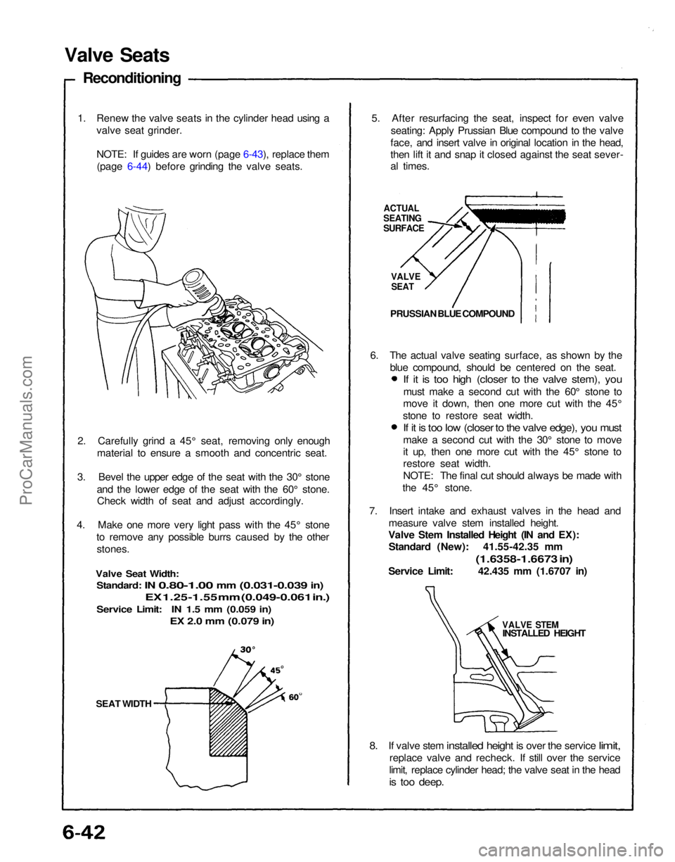
Valve Seat s
Reconditionin g
1. Rene w th e valv e seat s i n th e cylinde r hea d usin g a
valv e sea t grinder .
NOTE : I f guide s ar e wor n (se e pag e 6-39 ), replac e
the m (se e pag e 6-40 ) befor e grindin g th e valv e seats .
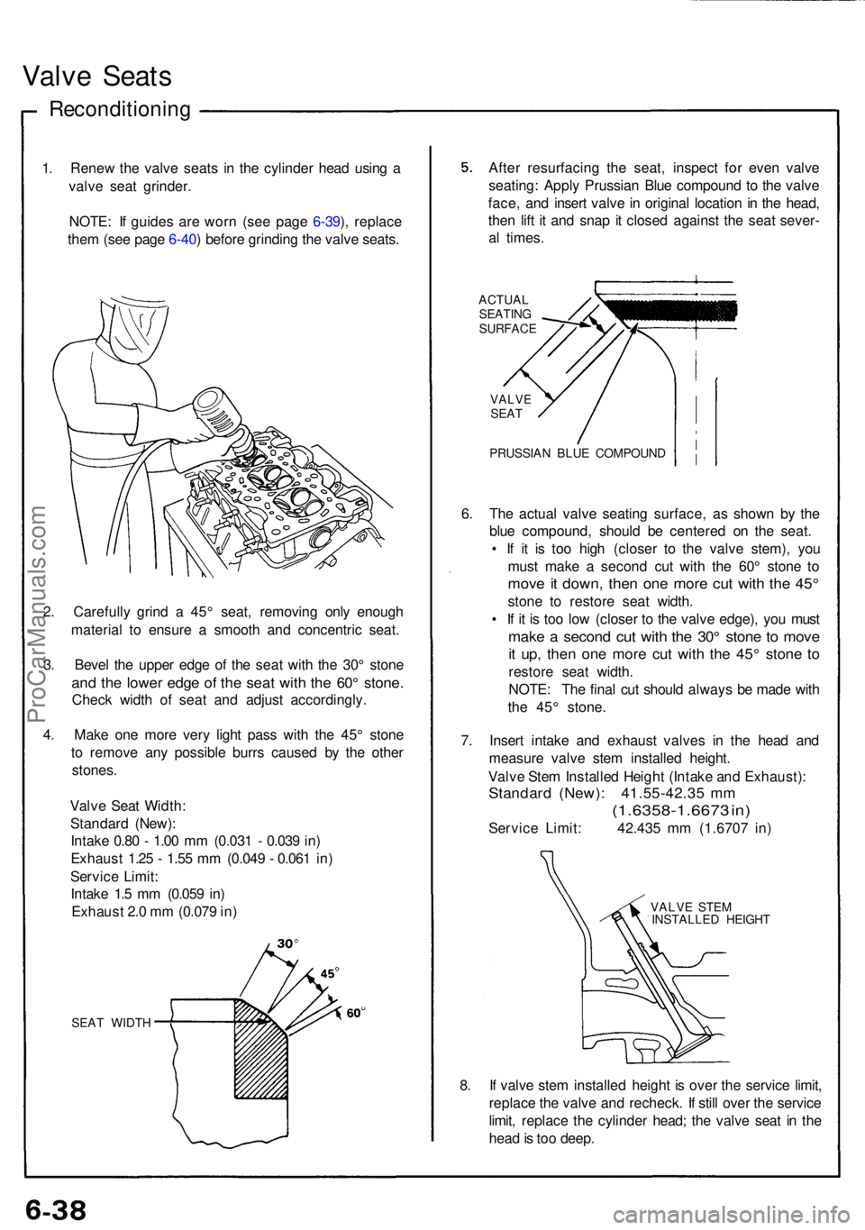
2 . Carefull y grin d a 45 ° seat , removin g onl y enoug h
materia l t o ensur e a smoot h an d concentri c seat .
3 . Beve l th e uppe r edg e o f th e sea t wit h th e 30 ° ston e
and th e lowe r edg e of the sea t wit h th e 60 ° stone .
Check widt h o f sea t an d adjus t accordingly .
4 . Mak e on e mor e ver y ligh t pas s wit h th e 45 ° ston e
t o remov e an y possibl e burr s cause d b y th e othe r
stones .
Valv e Sea t Width :
Standar d (New) :
Intak e 0.8 0 - 1.0 0 m m (0.03 1 - 0.03 9 in )
Exhaus t 1.2 5 - 1.5 5 m m (0.04 9 - 0.06 1 in )
Servic e Limit :
Intak e 1. 5 m m (0.05 9 in )
Exhaus t 2. 0 m m (0.07 9 in )
SEA T WIDT H
After resurfacin g th e seat , inspec t fo r eve n valv e
seating : Appl y Prussia n Blu e compoun d t o th e valv e
face , an d inser t valv e in origina l locatio n in th e head ,
the n lif t i t an d sna p it close d agains t th e sea t sever -
a l times .
ACTUA L
SEATIN G
SURFAC E
VALVESEAT
PRUSSIA N BLU E COMPOUN D
6. Th e actua l valv e seatin g surface , a s show n b y th e
blu e compound , shoul d b e centere d o n th e seat .
• I f i t i s to o hig h (close r t o th e valv e stem) , yo u
mus t mak e a secon d cu t wit h th e 60 ° ston e t o
mov e it down , the n on e mor e cu t wit h th e 45 °
ston e t o restor e sea t width .
• I f i t i s to o lo w (close r t o th e valv e edge) , yo u mus t
make a secon d cu t wit h th e 30 ° ston e t o mov e
it up , the n on e mor e cu t wit h th e 45 ° ston e t o
restor e sea t width .
NOTE : Th e fina l cu t shoul d alway s b e mad e wit h
th e 45 ° stone .
7 . Inser t intak e an d exhaus t valve s i n th e hea d an d
measur e valv e ste m installe d height .
Valv e Ste m Installe d Heigh t (Intak e an d Exhaust) :
Standard (New) : 41.55-42.3 5 m m
(1.6358-1.667 3 in )
Servic e Limit : 42.43 5 m m (1.670 7 in )
VALV E STE M
INSTALLE D HEIGH T
8. I f valv e ste m installe d heigh t i s ove r th e servic e limit ,
replac e th e valv e an d recheck . I f stil l ove r th e servic e
limit , replac e th e cylinde r head ; th e valv e sea t i n th e
hea d is to o deep .
ProCarManuals.com
Page 311 of 1640
Reverse Shift Arm, Reverse Shift Fork
Clearance Inspection
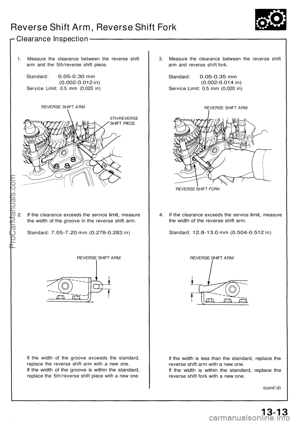
1. Measure the clearance between the reverse shift
arm and the 5th/reverse shift piece.
Standard:
0.05-0.30
mm
(0.002-0.012 in)
Service Limit: 0.5 mm (0.020 in)
REVERSE SHIFT ARM
5TH/REVERSE
SHIFT PIECE
2. If the
clearance exceeds
the
service
limit,
measure
the width of the groove in the reverse shift arm.
Standard:
7.05-7.20
mm
(0.278-0.283
in)
REVERSE SHIFT ARM
If the width of the groove exceeds the standard,
replace the reverse shift arm with a new one.
If the width of the groove is within the standard,
replace the 5th/reverse shift piece with a new one.
3. Measure the clearance between the reverse shift
arm and reverse shift fork.
Standard:
0.05-0.35
mm
(0.002-0.014 in)
Service Limit: 0.5 mm (0.020 in)
REVERSE SHIFT ARM
REVERSE SHIFT FORK
4. If the
clearance exceeds
the
service
limit,
measure
the width of the reverse shift arm.
Standard:
12.8-13.0
mm
(0.504-0.512
in)
REVERSE SHIFT ARM
If the width is less than the standard, replace the
reverse shift arm with a new one.
If the width is within the standard, replace the
reverse shift fork with a new one.ProCarManuals.com
Page 321 of 1640
Change Holder Assembly, Shift Fork
Clearance Inspection
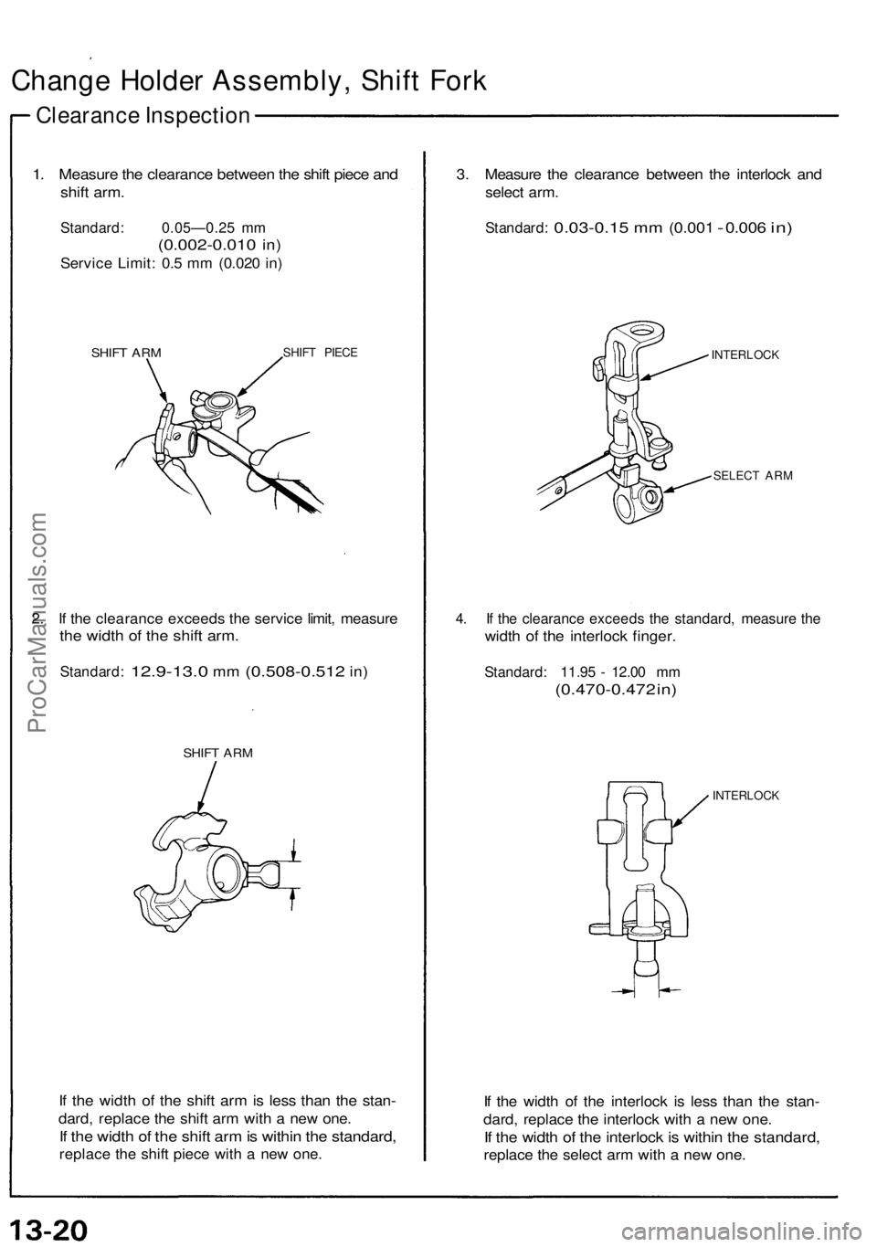
1. Measure the clearance between the shift piece and
shift arm.
Standard: 0.05—0.25 mm
(0.002-0.010
in)
Service Limit: 0.5 mm (0.020 in)
SHIFT ARM
SHIFT PIECE
2. If the clearance exceeds the service limit, measure
the width of the shift arm.
Standard:
12.9-13.0
mm
(0.508-0.512
in)
SHIFT ARM
If the width of the shift arm is less than the stan-
dard, replace the shift arm with a new one.
If the width of the shift arm is within the standard,
replace the shift piece with a new one.
3. Measure the clearance between the interlock and
select arm.
Standard:
0.03-0.15
mm
(0.001
-
0.006
in)
INTERLOCK
SELECT ARM
4. If the clearance exceeds the standard, measure the
width of the interlock finger.
Standard: 11.95 - 12.00 mm
(0.470-0.472 in)
INTERLOCK
If the width of the interlock is less than the stan-
dard, replace the interlock with a new one.
If the width of the interlock is within the standard,
replace the select arm with a new one.ProCarManuals.com
Page 322 of 1640
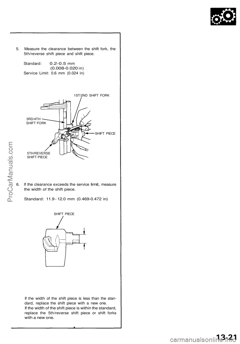
5. Measure the clearance between the shift fork, the
5th/reverse shift piece and shift piece.
Standard:
0.2-0.5
mm
(0.008-0.020
in)
Service Limit: 0.6 mm (0.024 in)
1ST/2ND SHIFT FORK
5TH/REVERSE
SHIFT PIECE
6. If the
clearance exceeds
the
service
limit,
measure
the width of the shift piece.
Standard: 11.9 - 12.0 mm (0.469-0.472 in)
SHIFT PIECE
If the width of the shift piece is less than the stan-
dard, replace the shift piece with a new one.
If the width of the shift piece is within the standard,
replace the 5th/reverse shift piece or shift forks
with a new one.
3RD/4TH
SHIFT FORK
SHIFT PIECEProCarManuals.com
Page 323 of 1640
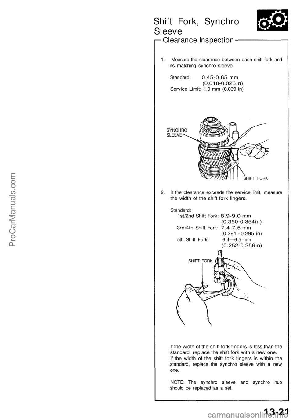
Shift Fork, Synchro
Sleeve
Clearance Inspection
1. Measure the clearance between each shift fork and
its matching synchro sleeve.
Standard:
0.45-0.65
mm
(0.018-0.026 in)
Service Limit: 1.0 mm (0.039 in)
SYNCHRO
SLEEVE
SHIFT FORK
2. If the clearance exceeds the service limit, measure
the width of the shift fork fingers.
Standard:
1st/2nd
Shift
Fork:
8.9-9.0
mm
(0.350-0.354 in)
3rd/4th
Shift
Fork:
7.4-7.5
mm
(0.291 - 0.295 in)
5th Shift Fork: 6.4—6.5 mm
(0.252-0.256 in)
SHIFT FORK
If the width of the shift fork fingers is less than the
standard, replace the shift fork with a new one.
If the width of the shift fork fingers is within the
standard, replace the synchro sleeve with a new
one.
NOTE: The synchro sleeve and synchro hub
should be replaced as a set.ProCarManuals.com
Page 414 of 1640
System Description
Function and Operation
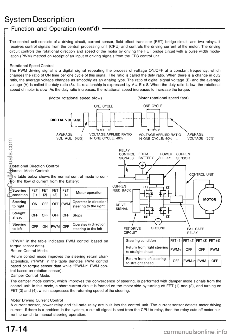
The control unit consists of a driving circuit, current sensor, field effect transistor (FET) bridge circuit, and two relays. It
receives control signals from the central processing unit (CPU) and controls the driving current of the motor. The driving
circuit controls the rotational direction and speed of the motor by driving the FET bridge circuit with a pulse width modu-
lation (PWM) method on receipt of an input of driving signals from the EPS control unit.
Rotational Speed Control
The PWM driving signal is a digital signal repeating the process of voltage ON/OFF at a constant frequency, which
changes the ratio of ON time per one cycle of this signal. The ratio is called the duty ratio. When there is a change in duty
ratio, the average voltage changes as smoothly as an analog type. The ratio of digital signal voltage (E) and the average
voltage (V) is called the duty ratio (8). Its relationship is expressed by V = E x 8. When the duty ratio is low, the rotational
speed of motor is slow. As the duty ratio increases, the rotational speed increases to increase the torque.
(Motor rotational speed slow)
ONE CYCLE
(Motor rotational speed fast)
ONE CYCLE
AVERAGE /
VOLTAGE (40%)
VOLTAGE APPLIED RATIO
IN ONE CYCLE: 40%
RELAY
CONTROL
SIGNALS
VOLTAGE APPLIED RATIO
IN ONE CYCLE: 60%
AVERAGE
VOLTAGE (60%)
FROM
BATTERY
POWER
RELAY
CURRENT
SENSOR
Rotational Direction Control
Normal Mode Control:
The table below shows the normal control mode to con-
trol the flow of current from the battery:
CURRENT
FEED BACK
DRIVE
SIGNAL
FET DRIVE
CIRCUIT
GROUND
FAIL SAFE
RELAY
("PWM" in the table indicates PWM control based on
torque sensor data).
Return Control Mode:
Return control mode improves the steering return char-
acteristics. ("PWM" in the table denotes PWM control
based on torque sensor data while "PWM-r" PWM con-
trol based on rotation sensor).
Damper Control Mode:
The damper mode control, which improves the convergence of steering, is performed with damper mode signals from the
control unit. In this mode, a short current circuit is formed on the motor side by turning off FET (1) and (2), and turning on
FET (3) and (4), which suppresses the returning speed of the steering.
Motor Driving Current Control
A current sensor, power relay and fail-safe relay are built into the control unit. The current sensor detects motor driving
current. If there is a problem in the system, a cut-off signal is sent from the CPU to relay, then the relay cuts off motor cur-
rent to switch to manual steering operation.
CONTROL UNITProCarManuals.com
Page 450 of 1640
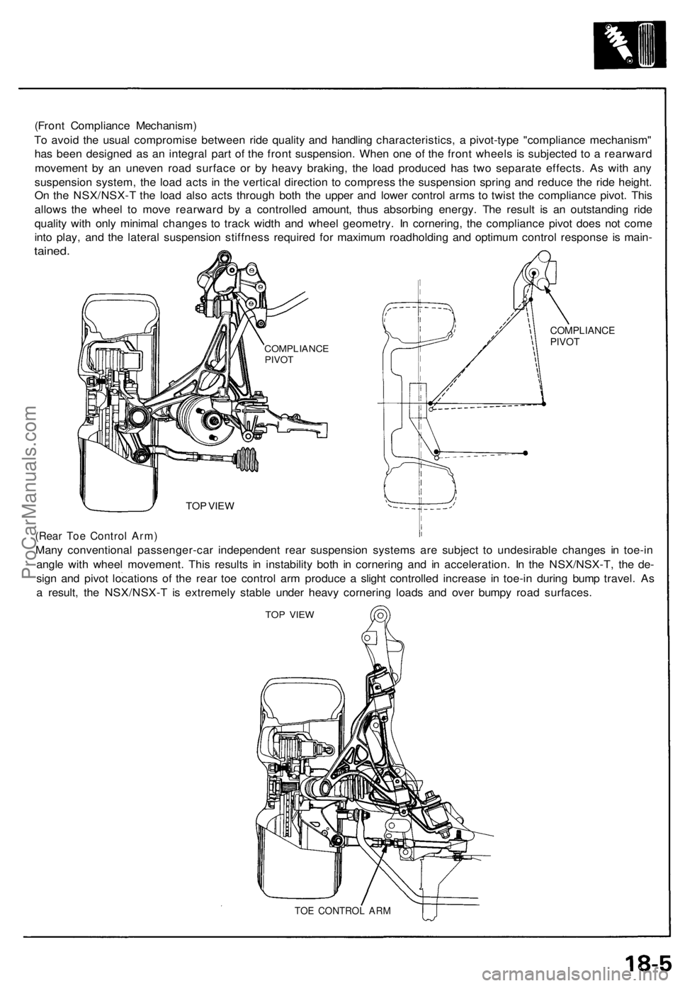
(Front Compliance Mechanism)
To avoid the usual compromise between ride quality and handling characteristics, a pivot-type "compliance mechanism"
has been designed as an integral part of the front suspension. When one of the front wheels is subjected to a rearward
movement by an uneven road surface or by heavy braking, the load produced has two separate effects. As with any
suspension system, the load acts in the vertical direction to compress the suspension spring and reduce the ride height.
On the NSX/NSX-T the load also acts through both the upper and lower control arms to twist the compliance pivot. This
allows the wheel to move rearward by a controlled amount, thus absorbing energy. The result is an outstanding ride
quality with only minimal changes to track width and wheel geometry. In cornering, the compliance pivot does not come
into play, and the lateral suspension stiffness required for maximum roadholding and optimum control response is main-
tained.
COMPLIANCE
PIVOT
TOP VIEW
(Rear Toe Control Arm)
Many conventional passenger-car independent rear suspension systems are subject to undesirable changes in toe-in
angle with wheel movement. This results in instability both in cornering and in acceleration. In the NSX/NSX-T, the de-
sign and pivot locations of the rear toe control arm produce a slight controlled increase in toe-in during bump travel. As
a result, the NSX/NSX-T is extremely stable under heavy cornering loads and over bumpy road surfaces.
TOP VIEW
TOE CONTROL ARM
COMPLIANCE
PIVOTProCarManuals.com
Page 643 of 1640
Roof
Roof Side Seal/Retainer Replacement
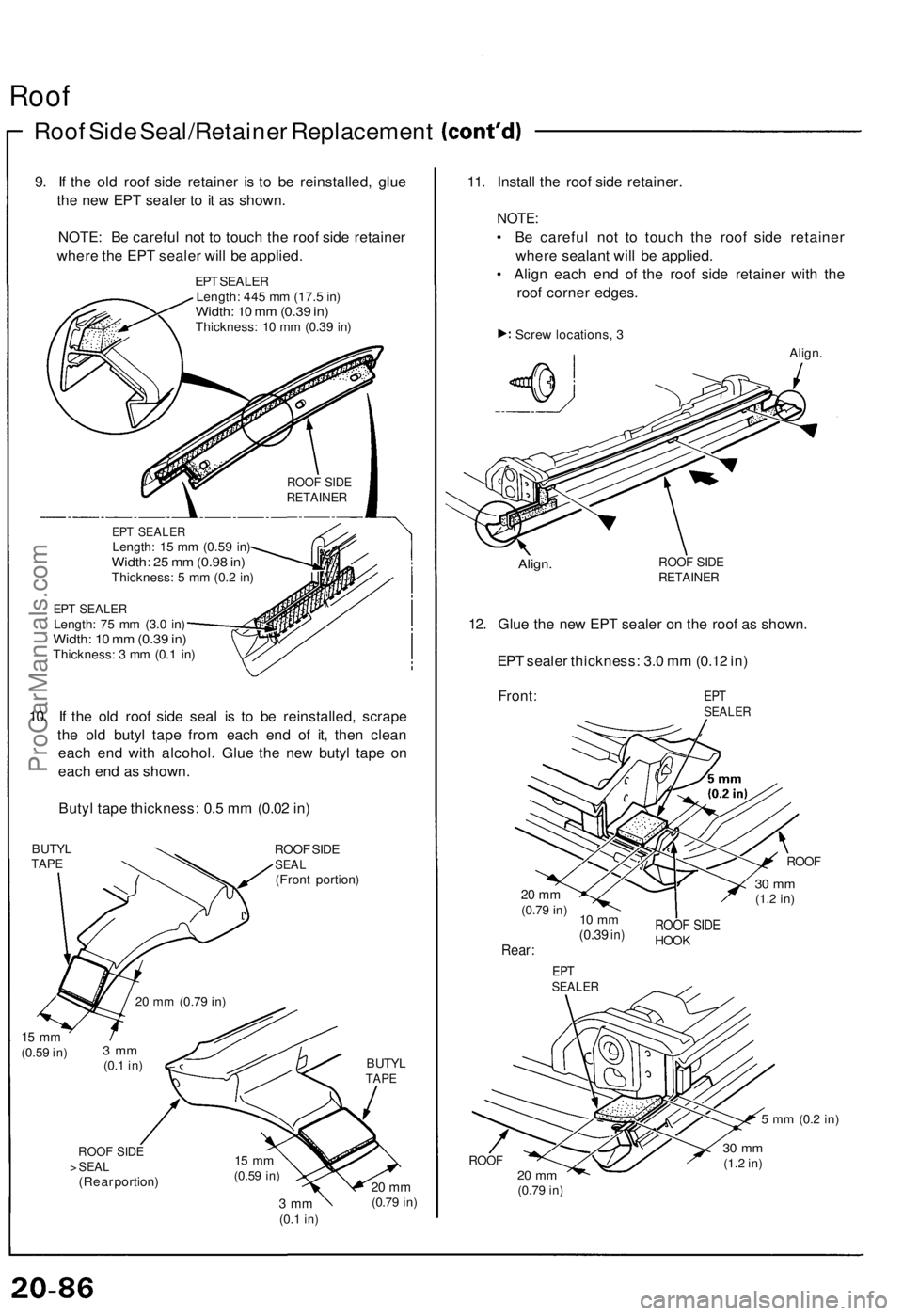
9. If the old roof side retainer is to be reinstalled, glue
the new EPT sealer to it as shown.
NOTE: Be careful not to touch the roof side retainer
where the EPT sealer will be applied.
EPT SEALER
Length: 445 mm (17.5 in)
Width: 10 mm (0.39 in)
Thickness: 10 mm (0.39 in)
EPT SEALER
Length: 15 mm (0.59 in)
Width: 25 mm (0.98 in)
Thickness: 5 mm (0.2 in)
EPT SEALER
Length: 75 mm (3.0 in)
Width: 10 mm (0.39 in)
Thickness: 3 mm (0.1 in)
10. If the old roof side seal is to be reinstalled, scrape
the old butyl tape from each end of it, then clean
each end with alcohol. Glue the new butyl tape on
each end as shown.
Butyl tape thickness: 0.5 mm (0.02 in)
BUTYL
TAPE
ROOF SIDE
SEAL
(Front portion)
15 mm
(0.59
in)
BUTYL
TAPE
ROOF SIDE
> SEAL
(Rear portion)
3 mm
(0.1
in)
20 mm
(0.79
in)
11. Install the roof side retainer.
NOTE:
• Be careful not to touch the roof side retainer
where sealant will be applied.
• Align each end of the roof side retainer with the
roof corner edges.
Screw locations, 3
Align.
Align.
ROOF SIDE
RETAINER
12. Glue the new EPT sealer on the roof as shown.
EPT sealer thickness: 3.0 mm (0.12 in)
Front:
EPT
SEALER
ROOF
20 mm
(0.79
in)
30 mm
(1.2
in)
10 mm
(0.39
in)
Rear:
ROOF SIDE
HOOK
EPT
SEALER
5 mm
(0.2
in)
ROOF
20 mm
(0.79
in)
30 mm
(1.2
in)
3 mm
(0.1
in)
20 mm
(0.79
in)
15 mm
(0.59
in)
ROOF SIDE
RETAINERProCarManuals.com
Page 1029 of 1640
SEAT WIDTH
2. Carefully grind a 45° seat, removing only enough
material to ensure a smooth and concentric seat.
3. Bevel the upper edge of the seat with the 30° stone and the lower edge of the seat with the 60° stone.Check width of seat and adjust accordingly.
4. Make one more very light pass with the 45° stone to remove any possible burrs caused by the otherstones.
Valve Seat Width:
Standard:
IN
0.80-1.00
mm
(0.031-0.039
in)
EX 1.25-1.55 mm (0.049-0.061 in.)
Service Limit: IN 1.5 mm (0.059 in)
EX 2.0 mm (0.079 in)
1. Renew the valve seats in the cylinder head using a
valve seat grinder.
NOTE: If guides are worn (page 6-43), replace them(page 6-44) before grinding the valve seats.
Valve Seats
Reconditioning
5. After resurfacing the seat, inspect for even valveseating: Apply Prussian Blue compound to the valve
face, and insert valve in original location in the head,
then lift it and snap it closed against the seat sever-
al times.
ACTUAL
SEATING
SURFACE
VALVE
SEAT
PRUSSIAN BLUE COMPOUND
7. Insert intake and exhaust valves in the head and measure valve stem installed height.
Valve Stem Installed Height (IN and EX): Standard (New): 41.55-42.35 mm
(1.6358-1.6673 in)
Service Limit: 42.435 mm (1.6707 in)
VALVE STEM
INSTALLED HEIGHT
8. If
valve stem
installed
height
is
over
the
service
limit,
replace valve and recheck. If still over the service
limit, replace cylinder head; the valve seat in the head
is too deep.
6. The actual valve seating surface, as shown by the
blue compound, should be centered on the seat.
If it is too high (closer to the valve stem), you
must make a second cut with the 60° stone to
move it down, then one more cut with the 45°
stone to restore seat width.
If it is too low (closer to the valve edge), you must
make a second cut with the 30° stone to move
it up, then one more cut with the 45° stone to
restore seat width.
NOTE: The final cut should always be made with
the 45° stone.ProCarManuals.com
Page 1331 of 1640

System Description
Power Unit
The power unit consists of a driving circuit, current sensor, field effect transistor (FET) bridge circuit, and two relays.
It receives control signals from the CPU and controls the driving current of the motor. The driving circuit controls the
rotational direction and speed of the motor by driving the FET bridge circuit with a pulse width modulation (PWM) method
on receipt of an input of driving signals from the EPS control unit.
< Rotational Speed Control >
The PWM driving signal is a digital signal repeating the process of voltage ON/OFF at a constant frequency, which changes the ratio of ON time per one cycle of this signal. The ratio is called the duty ratio. When there is a change in duty ratio,
the average voltage changes as smoothly as an analog type. The ratio of digital signal voltage (E) and the average voltage
(Motor rotational speed fast)
ONE CYCLE
AVERAGE
VOLTAGE (60%)
VOLTAGE APPLIED RATIO
IN ONE CYCLE: 60%
CURRENT
SENSOR
POWER
RELAY
FROM
BATTERY
RELAY
CONTROL
SIGNALS
VOLTAGE APPLIED RATIO
IN ONE CYCLE: 40%
AVERAGE
VOLTAGE (40%)
(Motor rotational speed slow)
DIGITAL VOLTAGE
ONE CYCLE
CURRENT
FEED BACK
DRIVE
SIGNAL
< Rotational Direction Control >
Normal Mode Control:
The table below shows the normal control mode to con-
trol the flow of current from the battery:
("PWM" in the table indicates PWM control based on
torque sensor data). Return Control Mode:
Return control mode improves the steering return charac-
teristics. ("PWM" in the table denotes PWM control based on torque sensor data while "PWM-r" PWM con-
trol based on rotation sensor).
POWER UNIT
FET DRIVE
CIRCUIT
GROND
FAIL SAFE
RELAY
Damper Control Mode:
The damper mode control which improves the convergence of steering, is performed with damper mode signals from
the control unit. In this mode, a short current circuit is formed on the motor side by turning off FET (1) and (2), and on FET (3) and (4), which suppresses the returning speed of the steering. < Motor Driving Current Control >
A current sensor, power relay and fail-safe relay are built into the power unit. The current sensor detects motor driving
current and transmits data to the EPS control unit. If there is a problem in the system, a cut-off signal is sent from the EPS
control unit to relay, then the relay cuts off motor current to switch to manual steering operation. (V) is called the duty ratio
of motor is slow. As the duty ratio increases, the rotational speed increases to increase the torque. When the duty ratio is low, the rotational speed
Its relationship is expressed by V = E x
Steering
condition Steering to
rightStraight
ahead
Steering to
left
OFFOFF
ON
FET
(1)
FET
(2)
FET
(3)
FET
(4)
OFF
OFF
OFF
ON
OFF
PWM
OFF
OFF
PWM
Motor operation
Stops
Operates in direction
steering to the left Operates in direction
steering to the right
Steering condition
Return from right steering
to straight ahead
Return from left steering
to straight ahead
FET (1)
PWM-r
OFF
FET (2)
OFF
PWM-r
FET (3)
OFF
PWM
OFF
PWM
FET (4)
MOTORProCarManuals.com