airbag off ACURA NSX 1997 Service Repair Manual
[x] Cancel search | Manufacturer: ACURA, Model Year: 1997, Model line: NSX, Model: ACURA NSX 1997Pages: 1503, PDF Size: 57.08 MB
Page 1366 of 1503
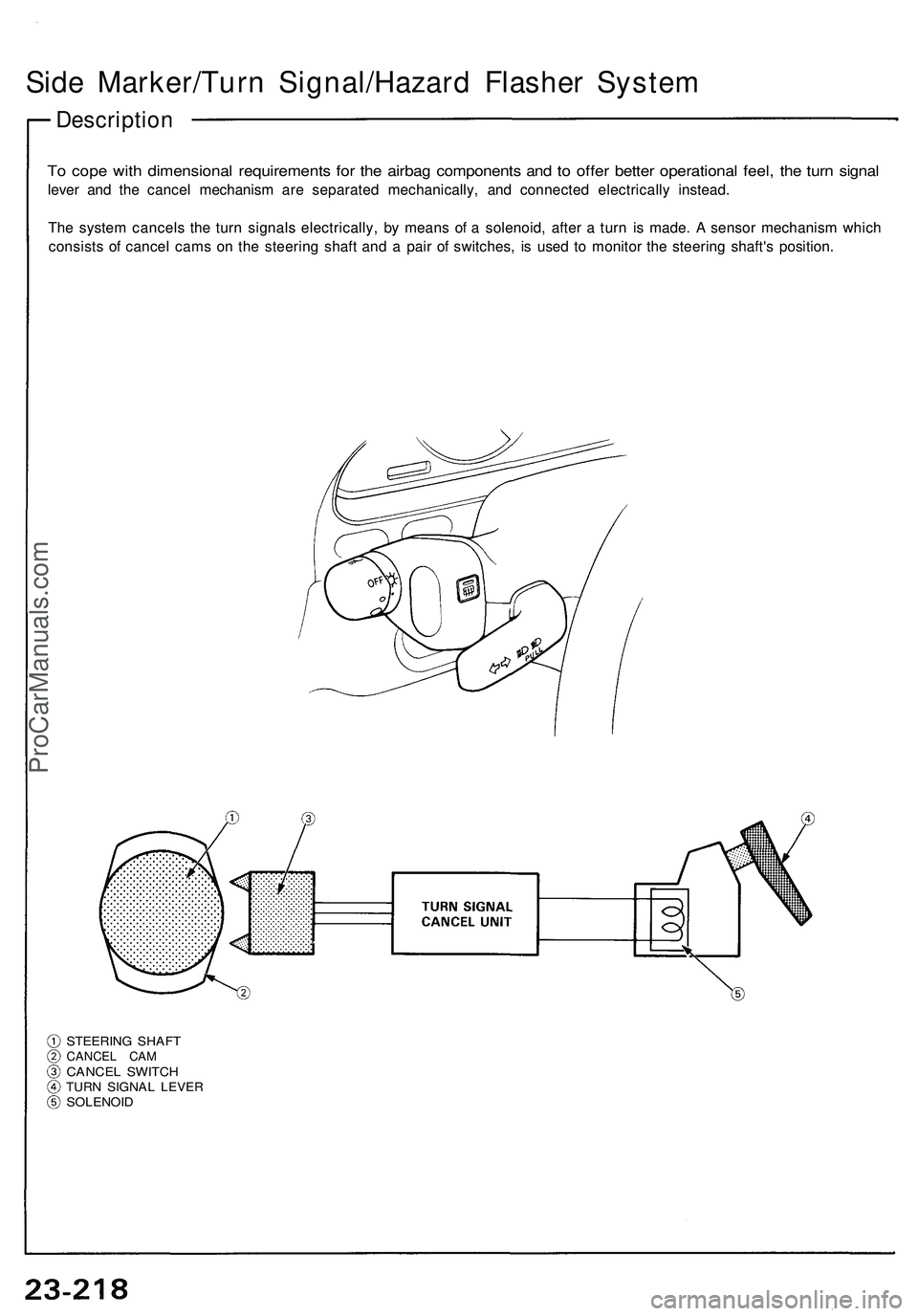
Side Marker/Turn Signal/Hazard Flasher System
Description
To cope with dimensional requirements for the airbag components and to offer better operational feel, the turn signal
lever and the cancel mechanism are separated mechanically, and connected electrically instead.
The system cancels the turn signals electrically, by means of a solenoid, after a turn is made. A sensor mechanism which
consists of cancel cams on the steering shaft and a pair of switches, is used to monitor the steering shaft's position.
STEERING SHAFT
CANCEL CAM
CANCEL SWITCH
TURN SIGNAL LEVER
SOLENOIDProCarManuals.com
Page 1482 of 1503
Supplemental Restrain t Syste m (SRS )
After a collisio n i n whic h th e airbag s wer e deployed , in -
spec t th e following :
1 . Inspec t th e das h sensor s fo r physica l damage . I f
th e sensor s ar e damaged , replac e them .
2 . Inspec t al l th e SR S wir e harnesses . Replace , don' t
repair , an y damage d harnesses .
3 . Inspec t th e cabl e ree l fo r hea t damage . I f ther e i s
an y damage , replac e th e cabl e reel .
4 . Remov e th e passenger' s lowe r dashboar d panel ,
th e glov e bo x lid , an d th e glov e box . Remov e th e
passenger' s airba g assembly , th e mountin g
bracket , an d fram e fro m th e dashboard . Remov e
th e suppor t bracke t fro m th e steerin g colum n
beam .
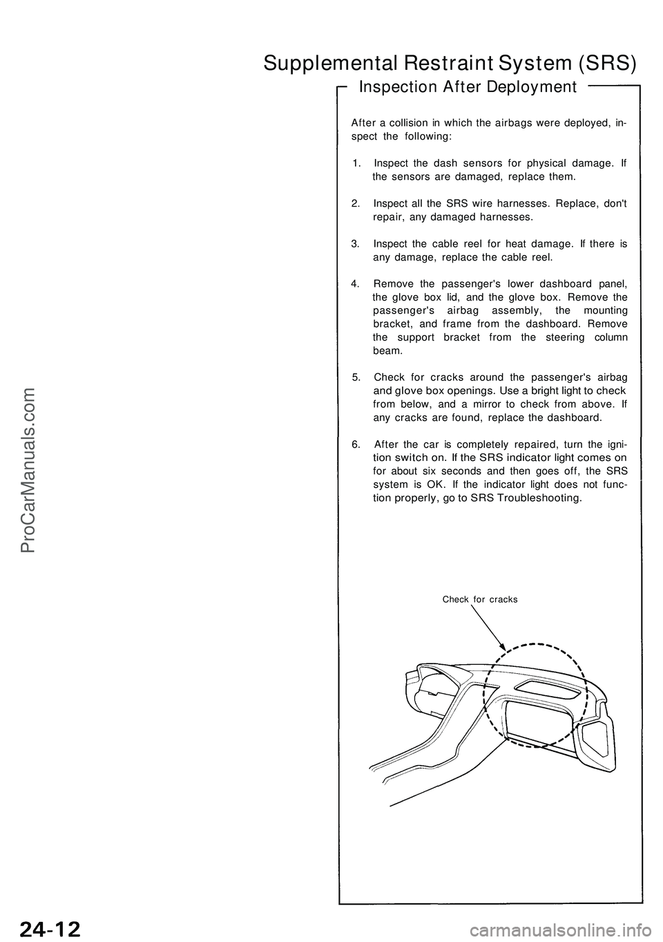
5 . Chec k fo r crack s aroun d th e passenger' s airba g
and glov e bo x openings . Us e a brigh t ligh t t o chec k
from below , an d a mirro r t o chec k fro m above . I f
an y crack s ar e found , replac e th e dashboard .
6 . Afte r th e ca r i s completel y repaired , tur n th e igni -
tion switc h on . I f th e SR S indicato r ligh t come s o n
fo r abou t si x second s an d the n goe s off , th e SR S
syste m is OK . I f th e indicato r ligh t doe s no t func -
tion properly , g o to SR S Troubleshooting .
Check fo r crack s
Inspectio n Afte r Deploymen t
ProCarManuals.com
Page 1483 of 1503
Troubleshooting
Self-diagnosis Functio n
The SR S uni t include s a self-diagnosi s function . I f ther e
i s a failur e in th e sensors , SR S unit , inflator , o r thei r cir -
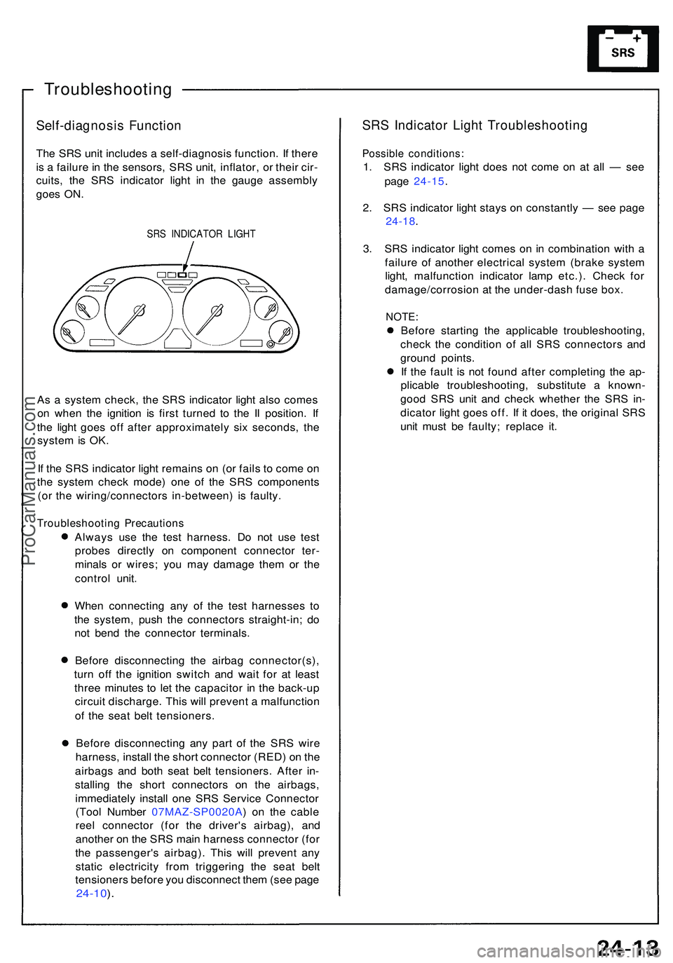
cuits , th e SR S indicato r ligh t i n th e gaug e assembl y
goe s ON .
SRS INDICATO R LIGH T
As a syste m check , th e SR S indicato r ligh t als o come s
o n whe n th e ignitio n i s firs t turne d t o th e I I position . I f
th e ligh t goe s of f afte r approximatel y si x seconds , th e
syste m is OK .
I f th e SR S indicato r ligh t remain s o n (o r fail s t o com e o n
th e syste m chec k mode ) on e o f th e SR S component s
(o r th e wiring/connector s in-between ) i s faulty .
Troubleshootin g Precaution s
Always us e th e tes t harness . D o no t us e tes t
probe s directl y o n componen t connecto r ter -
minal s o r wires ; yo u ma y damag e the m o r th e
contro l unit .
Whe n connectin g an y o f th e tes t harnesse s t o
th e system , pus h th e connector s straight-in ; d o
no t ben d th e connecto r terminals .
Befor e disconnectin g th e airba g connector(s) ,
tur n of f th e ignitio n switc h an d wai t fo r a t leas t
thre e minute s t o le t th e capacito r i n th e back-u p
circui t discharge . Thi s wil l preven t a malfunctio n
o f th e sea t bel t tensioners .
Befor e disconnectin g an y par t o f th e SR S wir e
harness , instal l th e shor t connecto r (RED ) o n th e
airbag s an d bot h sea t bel t tensioners . Afte r in -
stallin g th e shor t connector s o n th e airbags ,
immediatel y instal l on e SR S Servic e Connecto r
(Too l Numbe r 07MAZ-SP0020A ) o n th e cabl e
ree l connecto r (fo r th e driver' s airbag) , an d
anothe r o n th e SR S mai n harnes s connecto r (fo r
th e passenger' s airbag) . Thi s wil l preven t an y
stati c electricit y fro m triggerin g th e sea t bel t
tensioner s befor e yo u disconnec t the m (se e pag e
24-10 ).
SR S Indicato r Ligh t Troubleshootin g
Possible conditions :
1. SR S indicato r ligh t doe s no t com e o n a t al l — se e
pag e 24-15 .
2 . SR S indicato r ligh t stay s o n constantl y — se e pag e
24-18 .
3 . SR S indicato r ligh t come s o n in combinatio n wit h a
failur e o f anothe r electrica l syste m (brak e syste m
light , malfunctio n indicato r lam p etc.) . Chec k fo r
damage/corrosio n a t th e under-das h fus e box .
NOTE :
Before startin g th e applicabl e troubleshooting ,
chec k th e conditio n o f al l SR S connector s an d
groun d points .
I f th e faul t i s no t foun d afte r completin g th e ap -
plicabl e troubleshooting , substitut e a known -
goo d SR S uni t an d chec k whethe r th e SR S in -
dicato r ligh t goe s off . I f i t does , th e origina l SR S
uni t mus t b e faulty ; replac e it .
ProCarManuals.com
Page 1487 of 1503
Supplemental Restrain t Syste m (SRS )
Airbag Assembl y Installatio n
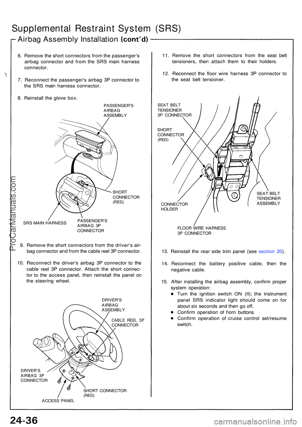
6. Remov e th e shor t connector s fro m th e passenger' s
airba g connecto r an d fro m th e SR S mai n harnes s
connector .
7 . Reconnec t th e passenger' s airba g 3 P connecto r t o
th e SR S mai n harnes s connector .
8 . Reinstal l th e glov e box .
PASSENGER' SAIRBAGASSEMBL Y
SHORTCONNECTO R(RED)
SRS MAI N HARNES SPASSENGER' SAIRBAG 3 PCONNECTO R
9. Remov e th e shor t connector s fro m th e driver' s air -
ba g connecto r an d fro m th e cabl e ree l 3 P connector .
10 . Reconnec t th e driver' s airba g 3 P connecto r t o th e
cabl e ree l 3 P connector . Attac h th e shor t connec -
to r t o th e acces s panel , the n reinstal l th e pane l o n
th e steerin g wheel .
DRIVER' SAIRBAGASSEMBL Y
CABLE REE L 3 PCONNECTO R
11. Remov e th e shor t connector s fro m th e sea t bel t
tensioners , the n attac h the m to thei r holders .
12 . Reconnec t th e floo r wir e harnes s 3 P connecto r t o
th e sea t bel t tensioner .
SEAT BEL TTENSIONE R3P CONNECTO R
SHORTCONNECTO R(RED)
DRIVER' SAIRBAG 3 PCONNECTO R
SHORT CONNECTO R(RED)ACCES S PANE L
CONNECTO RHOLDER
SEAT BEL TTENSIONE RASSEMBLY
FLOOR WIR E HARNES S3P CONNECTO R
13. Reinstal l th e rea r sid e tri m pane l (se e sectio n 20 ).
14. Reconnec t th e batter y positiv e cable , the n th e
negativ e cable .
15 . Afte r installin g th e airba g assembly , confir m prope r
syste m operation :
Tur n th e ignitio n switc h O N (II) ; th e instrumen t
pane l SR S indicato r ligh t shoul d com e o n fo r
abou t si x second s an d the n g o off .
Confir m operatio n o f hor n buttons .
Confir m operatio n of cruis e contro l set/resum e
switch .
ProCarManuals.com
Page 1490 of 1503
6. Connec t a 1 2 vol t batter y t o th e tool :
• I f th e gree n ligh t o n th e too l come s on , th e ten -
sione r ignite r circui t i s defective . G o t o Damage d
Airba g o r Tensione r Specia l Procedure .
• I f th e re d ligh t o n th e too l come s on , th e tension -
e r i s read y t o trigger .
7 . Pus h th e tool' s deploymen t switc h t o trigge r th e
tensione r igniter . Th e tensione r shoul d tak e u p th e
slac k i n th e bel t (po p th e cli p off) , an d loc k th e bel t
i n it s retracte d position .
• I f th e tensione r work s an d th e gree n ligh t o n th e
too l come s on , continu e wit h thi s procedure .
• I f th e tensione r doesn' t work , ye t th e gree n ligh t
come s on , it s ignite r i s defective . G o t o Damage d
Airba g o r Tensione r Specia l Procedure .
Durin g activation , th e tensione r ca n
becom e ho t enoug h to bur n you . Wai t thirt y minute s
afte r activatio n befor e touchin g it .
8 . Dispos e o f th e complet e tensione r assembly . N o
par t o f i t ca n b e reused .
9 . Repea t step s 3 thr u 8 on th e othe r sid e i f tha t
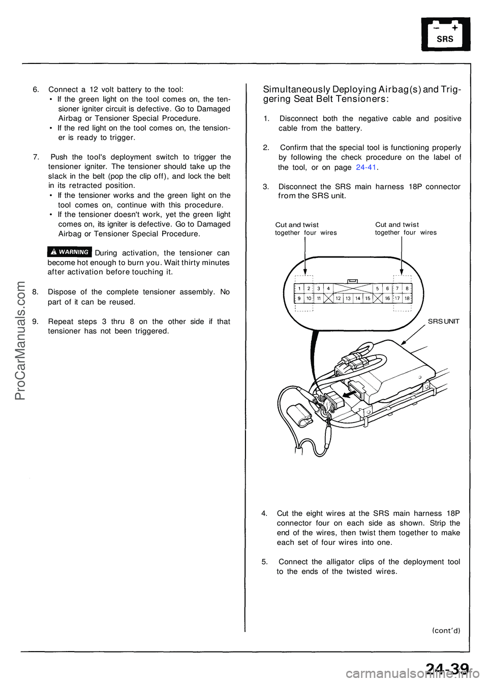
tensione r ha s no t bee n triggered .Simultaneousl y Deployin g Airbag(s ) an d Trig -
gerin g Sea t Bel t Tensioners :
1. Disconnec t bot h th e negativ e cabl e an d positiv e
cabl e fro m th e battery .
2 . Confir m tha t th e specia l too l i s functionin g properl y
b y followin g th e chec k procedur e o n th e labe l o f
th e tool , o r o n pag e 24-41 .
3 . Disconnec t th e SR S mai n harnes s 18 P connecto r
from th e SR S unit .
Cut an d twis ttogethe r fou r wire sCut an d twis ttogethe r fou r wire s
SRS UNI T
4. Cu t th e eigh t wire s a t th e SR S mai n harnes s 18 P
connecto r fou r o n eac h sid e a s shown . Stri p th e
en d o f th e wires , the n twis t the m togethe r t o mak e
eac h se t o f fou r wire s int o one .
5 . Connec t th e alligato r clip s o f th e deploymen t too l
t o th e end s o f th e twiste d wires .
ProCarManuals.com
Page 1499 of 1503
Supplemental Restrain t Syste m (SRS )
Dash Senso r Installatio n
CAUTION:
B e sur e t o instal l the harnes s wire s s o tha t the y ar e
no t pinche d o r interferin g wit h othe r ca r parts .
Replac e a senso r i f i t i s dented , cracke d o r deformed .
Fo r th e SR S t o functio n properly , th e righ t an d lef t
sensor s mus t b e installe d o n th e prope r sides .
1 . B e sur e th e batter y cable s ar e disconnected .
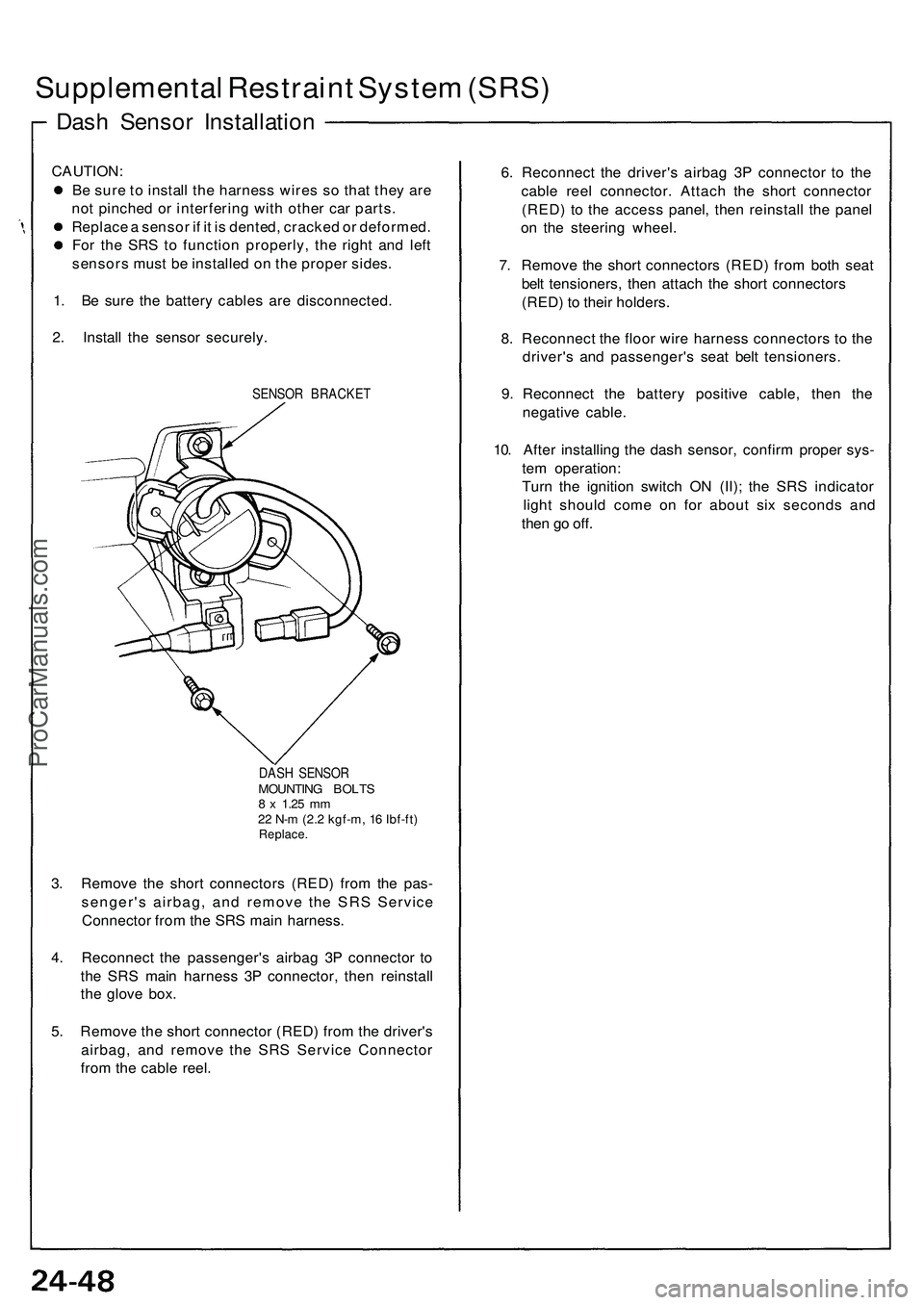
2 . Instal l th e senso r securely .
SENSOR BRACKE T
DAS H SENSO R
MOUNTIN G BOLT S8 x 1.2 5 mm22 N- m (2. 2 kgf-m , 1 6 Ibf-ft )Replace .
3. Remov e th e shor t connector s (RED ) fro m th e pas -
senger' s airbag , an d remov e th e SR S Servic e
Connecto r fro m th e SR S mai n harness .
4 . Reconnec t th e passenger' s airba g 3 P connecto r t o
th e SR S mai n harnes s 3 P connector , the n reinstal l
th e glov e box .
5 . Remov e th e shor t connecto r (RED ) fro m th e driver' s
airbag , an d remov e th e SR S Servic e Connecto r
fro m th e cabl e reel . 6
. Reconnec t th e driver' s airba g 3 P connecto r t o th e
cabl e ree l connector . Attac h th e shor t connecto r
(RED ) t o th e acces s panel , the n reinstal l th e pane l
o n th e steerin g wheel .
7 . Remov e th e shor t connector s (RED ) fro m bot h sea t
bel t tensioners , the n attac h th e shor t connector s
(RED ) t o their holders .
8 . Reconnec t th e floo r wir e harnes s connector s t o th e
driver' s an d passenger' s sea t bel t tensioners .
9 . Reconnec t th e batter y positiv e cable , the n th e
negativ e cable .
10 . Afte r installin g th e das h sensor , confir m prope r sys -
te m operation :
Tur n th e ignitio n switc h O N (II) ; th e SR S indicato r
ligh t shoul d com e o n fo r abou t si x second s an d
the n g o off .
ProCarManuals.com
Page 1501 of 1503
Supplemental Restraint System (SRS)
SRS Unit Assembly Installation
CAUTION: Be sure to install the SRS wiring so that it is
not pinched or interfering with other car parts.
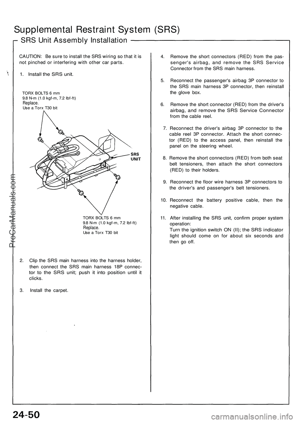
1. Install the SRS unit.
TORX BOLTS 6 mm
9.8 N-m (1.0 kgf-m, 7.2 Ibf-ft)
Replace.
Use a Torx T30 bit
TORX BOLTS 6 mm
9.8 N-m (1.0 kgf-m, 7.2 Ibf-ft)
Replace.
Use a Torx T30 bit
2. Clip the SRS main harness into the harness holder,
then connect the SRS main harness 18P connec-
tor to the SRS unit; push it into position until it
clicks.
3. Install the carpet.
4. Remove the short connectors (RED) from the pas-
senger's airbag, and remove the SRS Service
Connector from the SRS main harness.
5. Reconnect the passenger's airbag 3P connector to
the SRS main harness 3P connector, then reinstall
the glove box.
6. Remove the short connector (RED) from the driver's
airbag, and remove the SRS Service Connector
from the cable reel.
7. Reconnect the driver's airbag 3P connector to the
cable reel 3P connector. Attach the short connec-
tor (RED) to the access panel, then reinstall the
panel on the steering wheel.
8. Remove the short connectors (RED) from both seat
belt tensioners, then attach the short connectors
(RED) to their holders.
9. Reconnect the floor wire harness 3P connectors to
the driver's and passenger's belt tensioners.
10. Reconnect the battery positive cable, then the
negative cable.
11. After installing the SRS unit, confirm proper system
operation:
Turn the ignition switch ON (II); the SRS indicator
light should come on for about six seconds and
then go off.ProCarManuals.com
Page 1503 of 1503
Supplemental Restrain t Syste m (SRS )
Seat Bel t Tensione r Installatio n
CAUTION:
B e sur e t o instal l th e harnes s wire s s o tha t the y ar e
no t pinche d o r interferin g wit h othe r parts .
Be sur e th e batter y cable s ar e disconnected .
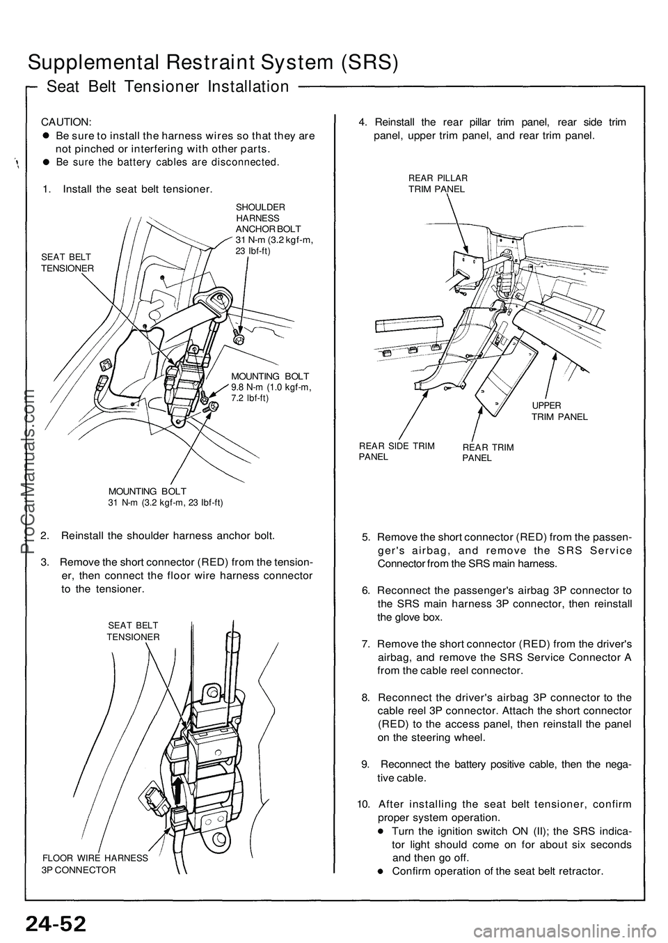
1. Instal l th e sea t bel t tensioner .
SEAT BEL TTENSIONE R
SHOULDERHARNESSANCHOR BOL T
3 1 N- m (3. 2 kgf-m ,
23 Ibf-ft )
MOUNTIN G BOL T9.8 N- m (1. 0 kgf-m ,7.2 Ibf-ft )
MOUNTIN G BOL T31 N- m (3. 2 kgf-m , 2 3 Ibf-ft )
2. Reinstal l th e shoulde r harnes s ancho r bolt .
3 . Remov e th e shor t connecto r (RED ) fro m th e tension -
er , the n connec t th e floo r wir e harnes s connecto r
t o th e tensioner .
SEAT BEL TTENSIONE R
FLOOR WIR E HARNES S3P CONNECTO R
4. Reinstal l th e rea r pilla r tri m panel , rea r sid e tri m
panel , uppe r tri m panel , an d rea r tri m panel .
REAR PILLA RTRIM PANE L
UPPERTRIM PANE L
REAR SID E TRI MPANE LREAR TRI MPANE L
5. Remov e th e shor t connecto r (RED ) fro m th e passen -
ger' s airbag , an d remov e th e SR S Servic e
Connecto r fro m th e SR S mai n harness .
6 . Reconnec t th e passenger' s airba g 3 P connecto r t o
th e SR S mai n harnes s 3 P connector , the n reinstal l
th e glov e box .
7 . Remov e th e shor t connecto r (RED ) fro m th e driver' s
airbag , an d remov e th e SR S Servic e Connecto r A
fro m th e cabl e ree l connector .
8 . Reconnec t th e driver' s airba g 3 P connecto r t o th e
cabl e ree l 3 P connector . Attac h th e shor t connecto r
(RED ) t o th e acces s panel , the n reinstal l th e pane l
o n th e steerin g wheel .
9 . Reconnec t th e batter y positiv e cable , the n th e nega -
tiv e cable .
10 . Afte r installin g th e sea t bel t tensioner , confir m
prope r syste m operation .
Tur n th e ignitio n switc h O N (II) ; th e SR S indica -
to r ligh t shoul d com e o n fo r abou t si x second s
an d the n g o off .
Confir m operatio n o f th e sea t bel t retractor .
ProCarManuals.com