charging ACURA NSX 1997 Service Repair Manual
[x] Cancel search | Manufacturer: ACURA, Model Year: 1997, Model line: NSX, Model: ACURA NSX 1997Pages: 1503, PDF Size: 57.08 MB
Page 595 of 1503
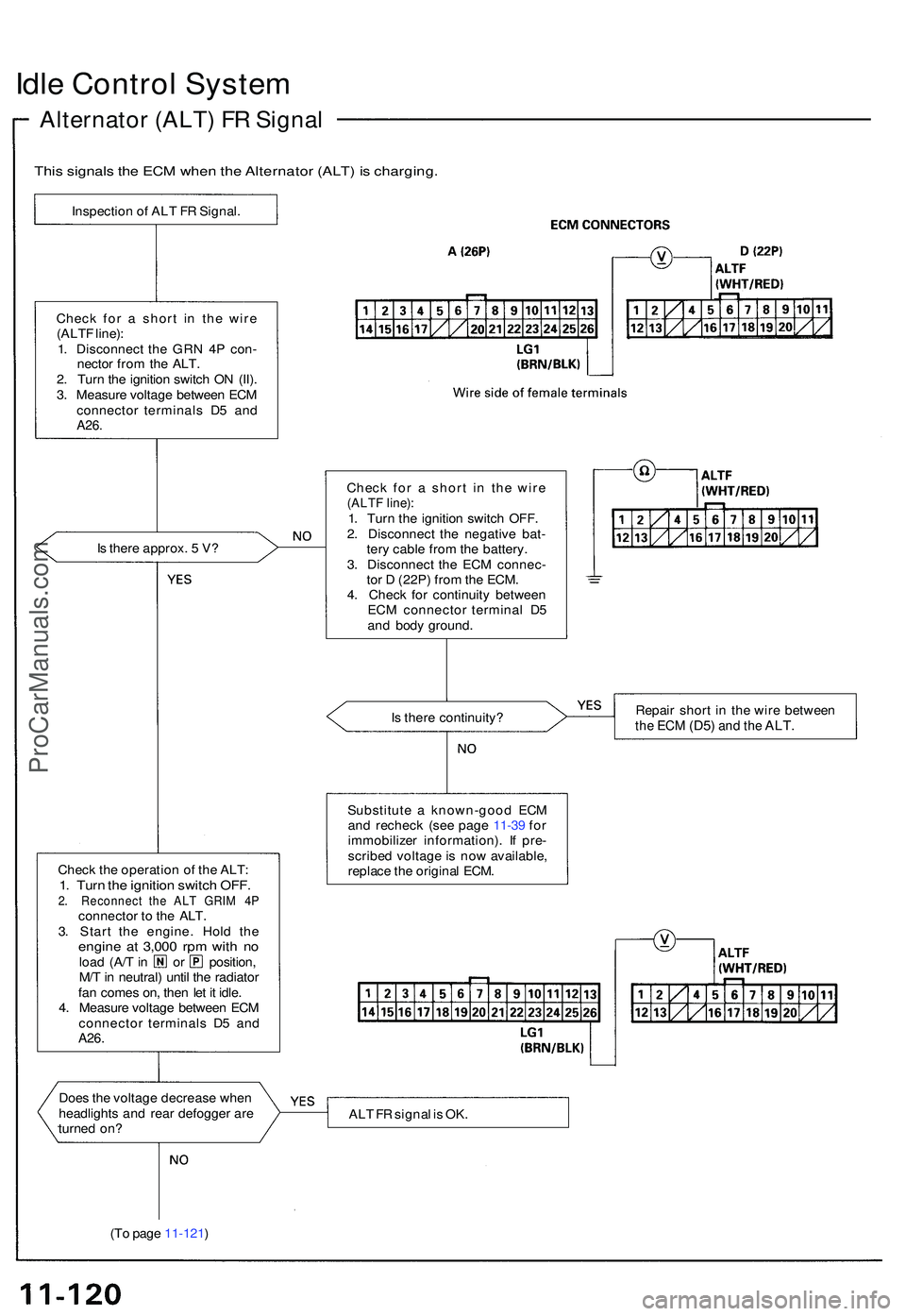
Idle Contro l Syste m
Alternato r (ALT ) F R Signa l
This signal s th e EC M whe n th e Alternato r (ALT ) i s charging .
Inspection o f AL T F R Signal .
Chec k fo r a shor t i n th e wir e
(ALT F line) :
1 . Disconnec t th e GR N 4 P con -
necto r fro m th e ALT .
2 . Tur n th e ignitio n switc h O N (II) .
3 . Measur e voltag e betwee n EC M
connecto r terminal s D 5 an d
A26.
Is ther e approx . 5 V ?
Chec k th e operatio n o f th e ALT :
1. Tur n th e ignitio n switc h OFF .2. Reconnec t th e AL T GRI M 4 Pconnecto r t o th e ALT .
3 . Star t th e engine . Hol d th e
engin e a t 3,00 0 rp m wit h n oloa d (A/ T in o r position ,
M/ T in neutral ) unti l th e radiato r
fa n come s on , the n le t i t idle .
4 . Measur e voltag e betwee n EC M
connecto r terminal s D 5 an d
A26 .
I
Doe s th e voltag e decreas e whe n
headlight s an d rea r defogge r ar e
turne d on ?
(T o pag e 11-121 ) Chec
k fo r a shor t i n th e wir e
(ALT F line) :1. Tur n th e ignitio n switc h OFF .
2 . Disconnec t th e negativ e bat -
ter y cabl e fro m th e battery .
3 . Disconnec t th e EC M connec -
to r D (22P ) fro m th e ECM .
4 . Chec k fo r continuit y betwee n
EC M connecto r termina l D 5
an d bod y ground .
I s ther e continuity ? Repai
r shor t i n th e wir e betwee n
the EC M (D5 ) and th e ALT .
Substitut e a known-goo d EC M
an d rechec k (se e pag e 11-3 9 fo r
immobilize r information) . I f pre -
scribe d voltag e is no w available ,
replac e th e origina l ECM .
AL T F R signa l i s OK .
ProCarManuals.com
Page 1207 of 1503
A/C System Service
Performance Test
The performance test will help determine if the air con-
ditioning system is operating within specifications.
Only use service equipment that is U.L.-listed and is cer-
tified to meet the requirements of SAE J2210 to remove
HFC-134a (R-134a) from the air conditioning system.
CAUTION: Exposure to air conditioner refrigerant
and lubricant vapor or mist can irritate eyes, nose
and throat. Avoid breathing the air conditioner
refrigerant and lubricant vapor or mist.
If accidental system discharge occurs, ventilate work
area before resuming service.
R-134a service equipment or vehicle air conditioning sys-
tem should not be pressure tested or leak tested with
compressed air.
Some mixtures of air and R-134a have
been shown to be combustible at elevated pressures
and can result in fire or explosion causing injury or
property damage. Never use compressed air to pres-
sure test R-134a service equipment or vehicle air
conditioning systems.
Additional health and safety information may be obtained
from the refrigerant and lubricant manufacturers.
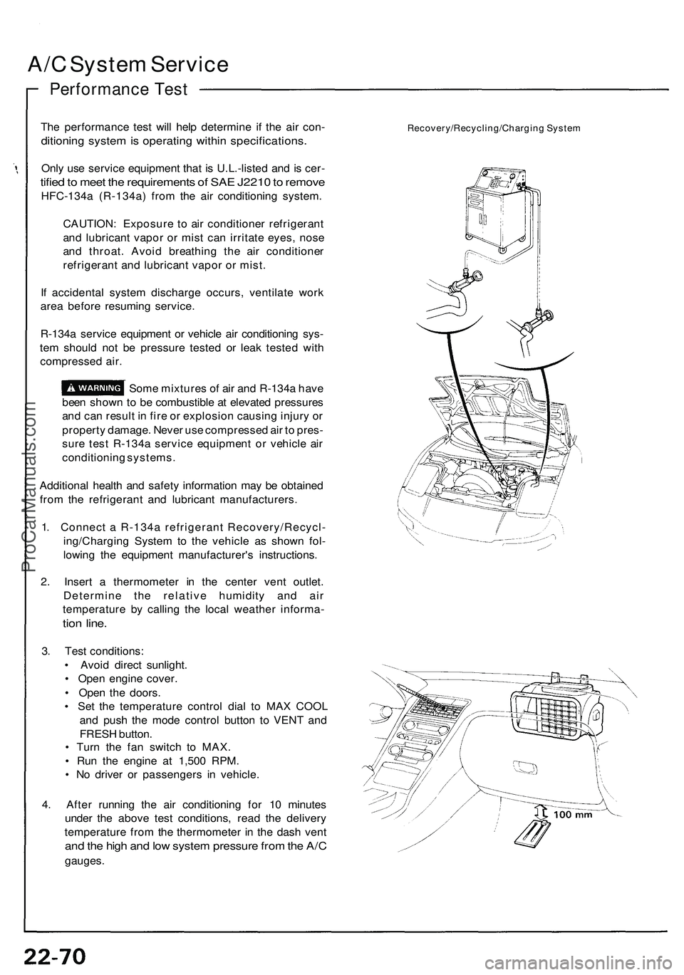
1. Connect a R-134a refrigerant Recovery/Recycl-
ing/Charging System to the vehicle as shown fol-
lowing the equipment manufacturer's instructions.
2. Insert a thermometer in the center vent outlet.
Determine the relative humidity and air
temperature by calling the local weather informa-
tion line.
3. Test conditions:
• Avoid direct sunlight.
• Open engine cover.
• Open the doors.
• Set the temperature control dial to MAX COOL
and push the mode control button to VENT and
FRESH button.
• Turn the fan switch to MAX.
• Run the engine at 1,500 RPM.
• No driver or passengers in vehicle.
4. After running the air conditioning for 10 minutes
under the above test conditions, read the delivery
temperature from the thermometer in the dash vent
and the high and low system pressure from the A/C
gauges.
Recovery/Recycling/Charging SystemProCarManuals.com
Page 1210 of 1503
Recovery
Only us e servic e equipmen t tha t i s U.L.-liste d an d i s cer -
tified t o mee t th e requirement s o f SA E J221 0 to remov e
HFC-134 a (R-134a ) fro m th e ai r conditionin g system .
CAUTION : Exposur e t o ai r conditione r refrigeran t
an d lubrican t vapo r o r mis t ca n irritat e eyes , nos e
an d throat . Avoi d breathin g th e ai r conditione r
refrigeran t an d lubrican t vapo r o r mist .
I f accidenta l syste m discharg e occurs , ventilat e wor k
are a befor e resumin g service .
R-134a servic e equipmen t o r vehicl e ai r conditionin g sys -
tem shoul d no t b e pressur e teste d o r lea k teste d wit h
compresse d air .
Som e mixture s o f ai r an d R-134 a hav e
bee n show n t o b e combustibl e a t elevate d pressure s
an d ca n resul t i n fir e o r explosio n causin g injur y o r
propert y damage . Neve r us e compresse d ai r t o pres -
sur e tes t R-134 a servic e equipmen t o r vehicl e ai r
conditionin g systems .
Additiona l healt h an d safet y informatio n ma y b e obtaine d
fro m th e refrigeran t an d lubrican t manufactures .
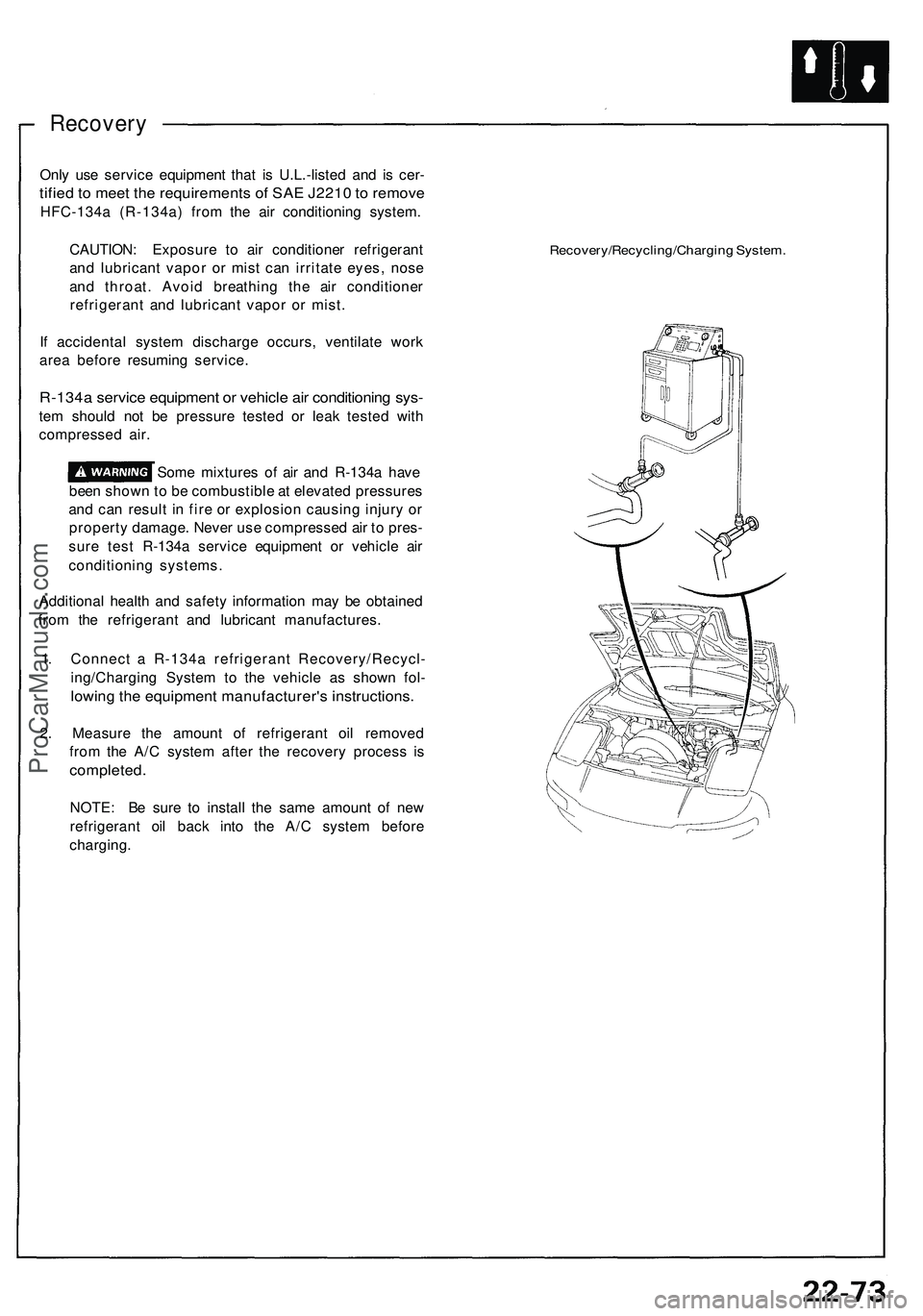
1 . Connec t a R-134 a refrigeran t Recovery/Recycl -
ing/Chargin g Syste m t o th e vehicl e a s show n fol -
lowin g th e equipmen t manufacturer' s instructions .
2. Measur e th e amoun t o f refrigeran t oi l remove d
fro m th e A/ C syste m afte r th e recover y proces s i s
completed .
NOTE: B e sur e t o instal l th e sam e amoun t o f ne w
refrigeran t oi l bac k int o th e A/ C syste m befor e
charging .
Recovery/Recycling/Chargin g System .
ProCarManuals.com
Page 1227 of 1503
A/C System Service
Evacuation
Only use service equipment that is U.L.-listed and is cer-
tified to meet the requirements of SAE J2210 to remove
HFC-134a (R-134a) from the air conditioning system.
CAUTION: Exposure to air conditioner refrigerant
and lubricant vapor or mist can irritate eyes, nose
and throat. Avoid breathing the air conditioner
refrigerant and lubricant vapor or mist.
If accidental system discharge occurs, ventilate work
area before resuming service.
R-134a service equipment or vehicle air conditioning sys-
tem should not be pressure tested or leak tested with
compressed air.
Some mixtures of air and R-134a have
been shown to be combustible at elevated pressures
and can result in fire or explosion causing injury or
property damage. Never use compressed air to pres-
sure test R-134a service equipment or vehicle air
conditioning systems.
Additional health and safety information may be obtained
from the refrigerant and lubricant manufacturers.
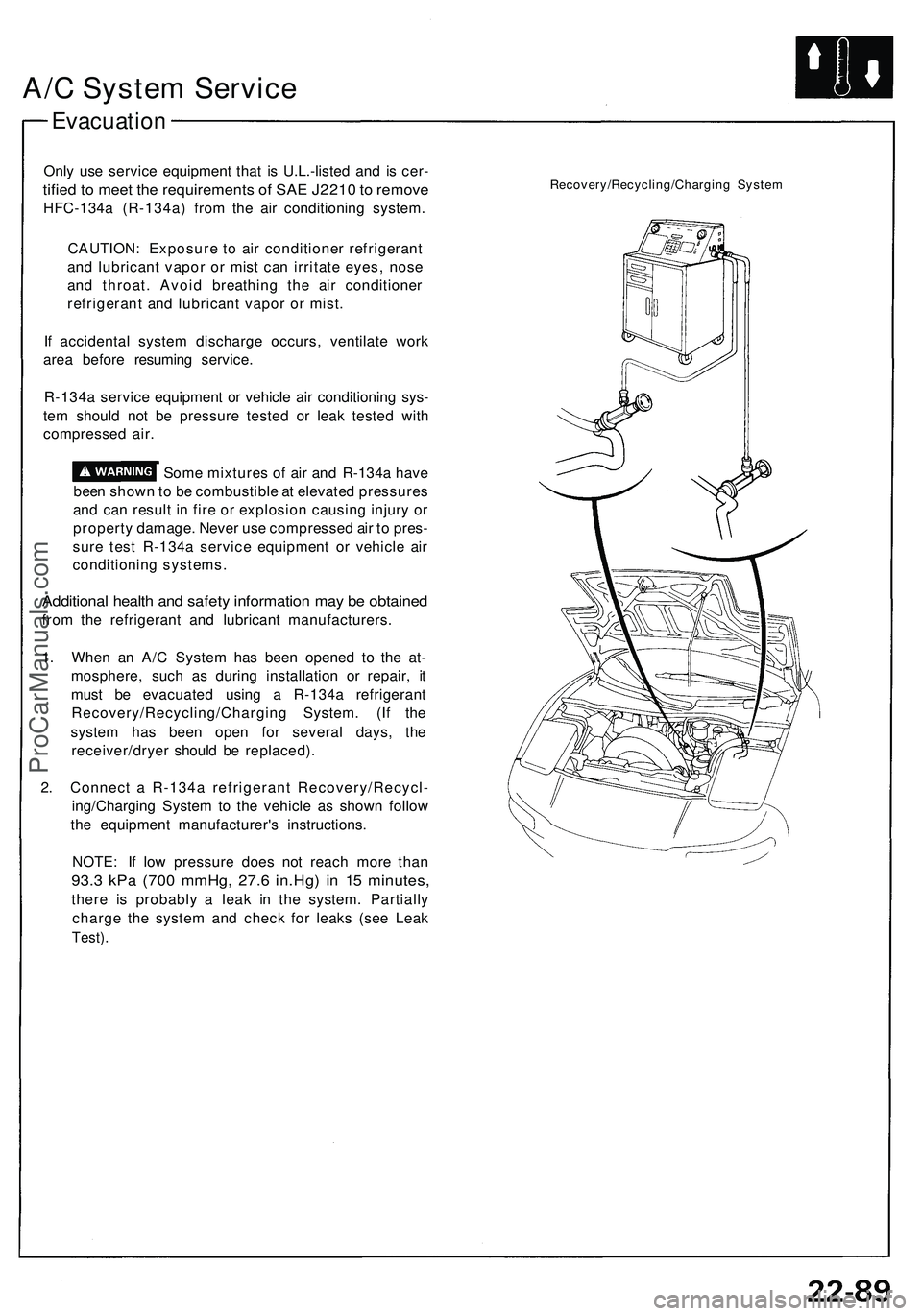
1. When an A/C System has been opened to the at-
mosphere, such as during installation or repair, it
must be evacuated using a R-134a refrigerant
Recovery/Recycling/Charging System. (If the
system has been open for several days, the
receiver/dryer should be replaced).
2. Connect a R-134a refrigerant Recovery/Recycl-
ing/Charging System to the vehicle as shown follow
the equipment manufacturer's instructions.
NOTE: If low pressure does not reach more than
93.3 kPa (700 mmHg, 27.6 in.Hg) in 15 minutes,
there is probably a leak in the system. Partially
charge the system and check for leaks (see Leak
Test).
Recovery/Recycling/Charging SystemProCarManuals.com
Page 1228 of 1503
A/C Syste m Servic e
Leak Tes t
Only us e servic e equipmen t tha t i s U.L.-liste d an d is cer -
tifie d t o mee t th e requirement s o f SA E J221 0 t o remov e
HFC-134 a (R-134a ) fro m th e ai r conditionin g system .
CAUTION : Exposur e t o ai r conditione r refrigeran t
an d lubrican t vapo r o r mis t ca n irritat e eyes , nos e
an d throat . Avoi d breathin g th e ai r conditione r
refrigeran t an d lubrican t vapo r o r mist .
I f accidenta l syste m discharg e occurs , ventilat e wor k
are a befor e resumin g service .
R-134a servic e equipmen t o r vehicl e ai r conditionin g sys -
tem shoul d no t b e pressur e teste d o r lea k teste d wit h
compresse d air .
Som e mixture s o f ai r an d R-134 a hav e
bee n show n to b e combustibl e a t elevate d pressure s
an d ca n resul t i n fir e o r explosio n causin g injur y o r
propert y damage . Neve r us e compresse d ai r t o pres -
sur e tes t R-134 a servic e equipmen t o r vehicl e ai r
conditione r systems.
Additiona l healt h an d safet y informatio n ma y b e obtaine d
fro m th e refrigeran t an d lubrican t manufacturers .
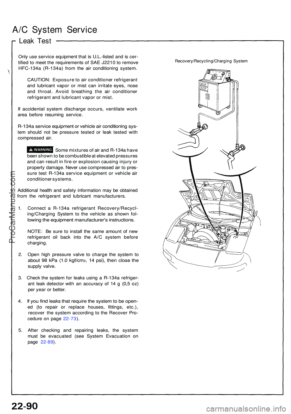
1 . Connec t a R-134 a refrigeran t Recovery/Recycl -
ing/Chargin g Syste m to th e vehicl e a s show n fol -
lowin g th e equipmen t manufacturer' s instructions .
NOTE: B e sur e t o instal l th e sam e amoun t o f ne w
refrigeran t oi l bac k int o th e A/ C syste m befor e
charging .
2 . Ope n hig h pressur e valv e t o charg e th e syste m to
abou t 9 8 kP a (1. 0 kgf/cm2, 1 4 psi) , the n clos e th e
suppl y valve .
3 . Chec k th e syste m fo r leak s usin g a R-134 a refriger -
an t lea k detecto r wit h a n accurac y o f 1 4 g (0, 5 oz )
pe r yea r o r better .
4. I f yo u fin d leak s tha t requir e th e syste m to b e open -
ed (t o repai r o r replac e houses , fittings , etc.) ,
recove r th e syste m accordin g t o th e Recove r Pro -
cedur e o n pag e 22-73 ).
5 . Afte r checkin g an d repairin g leaks , th e syste m
mus t b e evacuate d (se e Syste m Evacuatio n o n
pag e 22-89 ).
Recovery/Recycling/Chargin g Syste m
ProCarManuals.com
Page 1229 of 1503
Charging
Only use service equipment that is U.L.-listed and is
certified to meet the requirements of SAE J2210 to
remove HFC-134a (R-134a) from the air conditioner
system.
CAUTION: Exposure to air conditioner refrigerant
and lubricant vapor or mist can irritate eyes, nose
and throat. Avoid breathing the air conditioner
refrigerant and lubricant vapor or mist.
If accidental system discharge occurs, ventilate work
area before resuming service. Additional health and safe-
ty information may be obtained from the refrigerant and
lubricant manufacturers.
Refrigerant capacity: 850
CAUTION: Do not overcharge the system; the
compressor will be damaged.
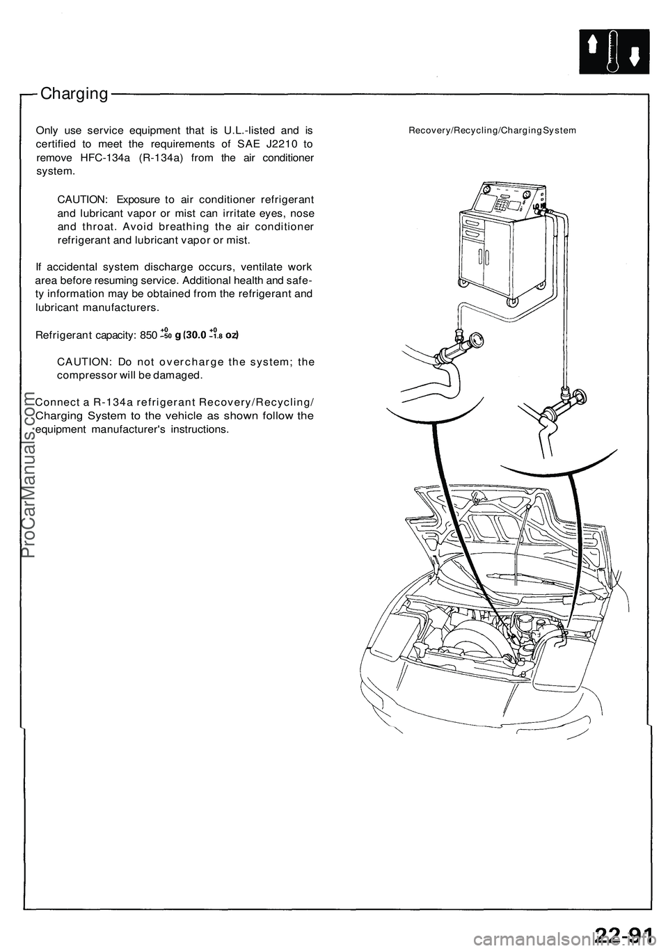
Connect a R-134a refrigerant Recovery/Recycling/
Charging System to the vehicle as shown follow the
equipment manufacturer's instructions.
Recovery/Recycling/Charging SystemProCarManuals.com
Page 1269 of 1503
Charging Syste m
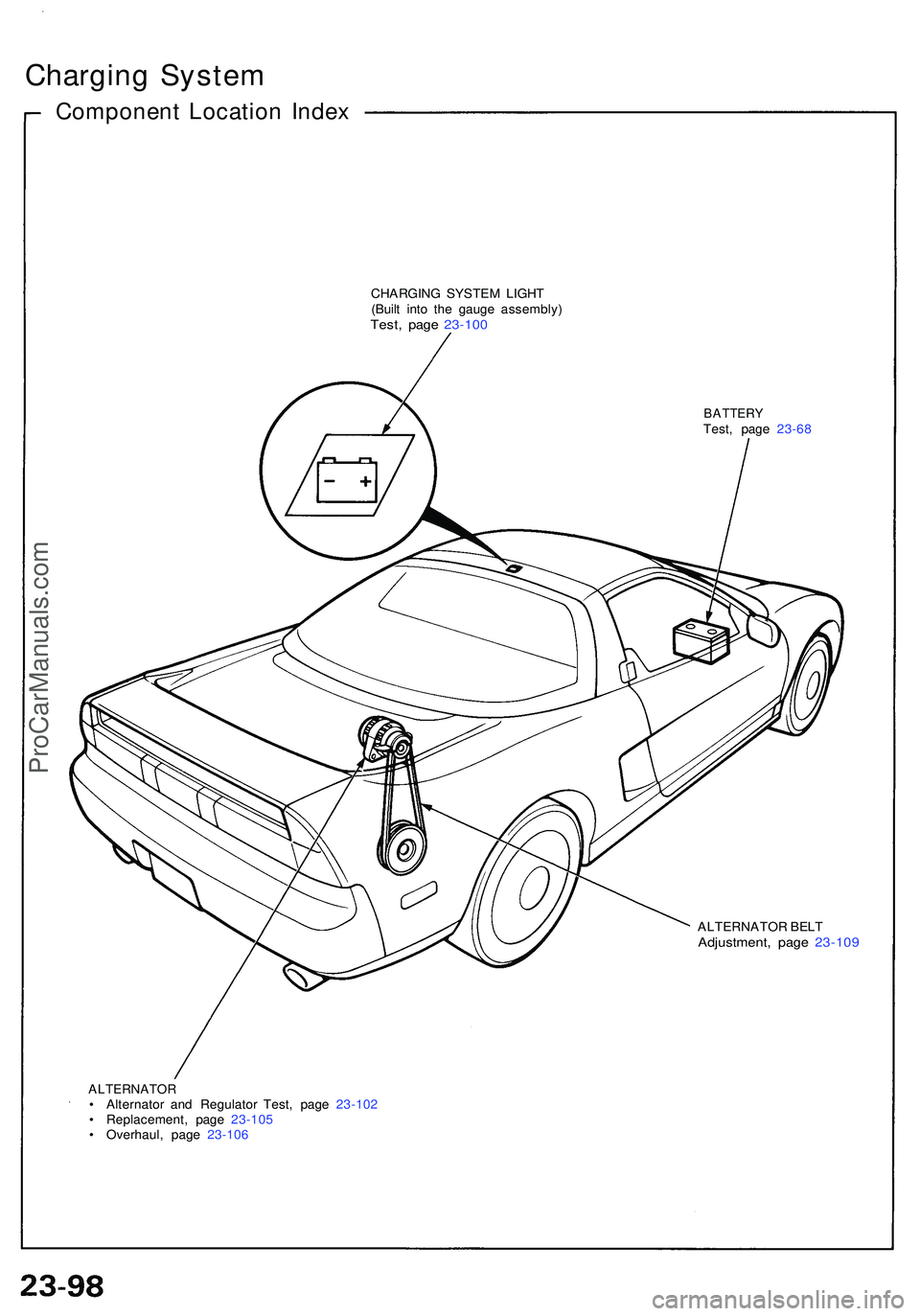
Componen t Locatio n Inde x
CHARGIN G SYSTE M LIGH T
(Buil t int o th e gaug e assembly )
Test, pag e 23-10 0
BATTER YTest, pag e 23-6 8
ALTERNATO R BEL T
Adjustment , pag e 23-10 9
ALTERNATO R• Alternato r an d Regulato r Test , pag e 23-10 2
• Replacement , pag e 23-10 5
• Overhaul , pag e 23-10 6
ProCarManuals.com
Page 1270 of 1503
Charging Syste m
Troubleshootin g
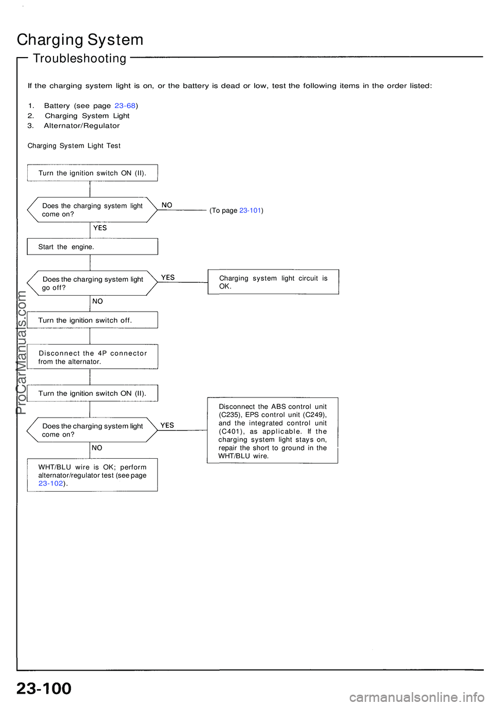
If th e chargin g syste m ligh t i s on , o r th e batter y i s dea d o r low , tes t th e followin g item s i n th e orde r listed :
1. Batter y (se e pag e 23-68 )
2 . Chargin g Syste m Ligh t
3 . Alternator/Regulato r
Charging Syste m Ligh t Tes t
Doe s th e chargin g syste m ligh t
com e on ?
Star t th e engine .
Does th e chargin g syste m ligh tgo off ?
Turn th e ignitio n switc h off .
Disconnec t th e 4 P connecto r
fro m th e alternator .
Turn th e ignitio n switc h O N (II) .
WHT/BL U wir e i s OK ; perfor m
alternator/regulato r tes t (se e pag e
23-102 ).
(T o page 23-101 )
Chargin g syste m ligh t circui t i s
OK .
Disconnec t th e AB S contro l uni t
(C235) , EP S contro l uni t (C249) ,
an d th e integrate d contro l uni t
(C401) , a s applicable . I f th e
chargin g syste m ligh t stay s on ,
repai r th e shor t t o groun d i n th e
WHT/BL U wire .
Does th e chargin g syste m ligh tcom e on ?
Tur
n th e ignitio n switc h O N (II) .
ProCarManuals.com
Page 1272 of 1503
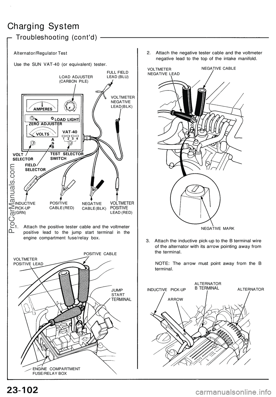
Charging System
Troubleshooting (cont'd)
Alternator/Regulator Test
Use the SUN VAT-40 (or equivalent) tester.
LOAD ADJUSTER
(CARBON PILE)
FULL FIELD
LEAD (BLU)
VOLTMETER
NEGATIVE
LEAD (BLK)
INDUCTIVE
PICK-UP
(GRN)
POSITIVE
CABLE (RED)
NEGATIVE
CABLE (BLK)
VOLTMETER
POSITIVE
LEAD (RED)
1. Attach the positive tester cable and the voltmeter
positive lead to the jump start terminal in the
engine compartment fuse/relay box.
POSITIVE CABLE
VOLTMETER
POSITIVE LEAD
JUMP
START
TERMINAL
ENGINE COMPARTMENT
FUSE/RELAY BOX
2. Attach the negative tester cable and the voltmeter
negative lead to the top of the intake manifold.
VOLTMETER
NEGATIVE LEAD
NEGATIVE CABLE
NEGATIVE MARK
3. Attach the inductive pick-up to the B terminal wire
of the alternator with its arrow pointing away from
the terminal.
NOTE: The arrow must point away from the B
terminal.
INDUCTIVE PICK-UP
ARROW
ALTERNATOR
B TERMINAL
ALTERNATORProCarManuals.com
Page 1273 of 1503

NOTE: B e sur e th e batter y i s sufficientl y charge d (se e
page 23-68 ).
Connec t th e Su n VAT-4 0 (se e
pag e 23-102 ) an d tur n th e selec -
to r switc h to positio n 1 (starting) .
Star t th e engine , an d le t i t idl e
unti l i t reache s norma l operatin g
temperature .
Rais e th e engin e spee d t o 2,00 0
rpm , an d hol d i t there .
I s th e voltag e ove r 15. 1 V ?
Replace th e voltag e regulator .
Releas e th e accelerato r pedal ,
an d le t th e engin e idle .
Mak e sur e al l accessorie s ar e
turne d off . Tur n th e selecto r
switch to positio n 2 (charging) .
Remove th e inductiv e pick-up ,
an d zer o th e ammeter .
Attac h th e inductiv e pick-u p t o
th e B termina l wir e o f th e alterna -tor wit h it s arro w pointin g awa y
fro m th e terminal .
Rais e th e engin e spee d t o 2,00 0
rpm , an d hol d it there .
I s th e voltag e les s tha n 13. 9 V ?
Test th e batter y (se e pag e 23-68 ).
(T o page 23-104 )
(cont'd)
ProCarManuals.com