seats ACURA NSX 1997 Service Repair Manual
[x] Cancel search | Manufacturer: ACURA, Model Year: 1997, Model line: NSX, Model: ACURA NSX 1997Pages: 1503, PDF Size: 57.08 MB
Page 291 of 1503
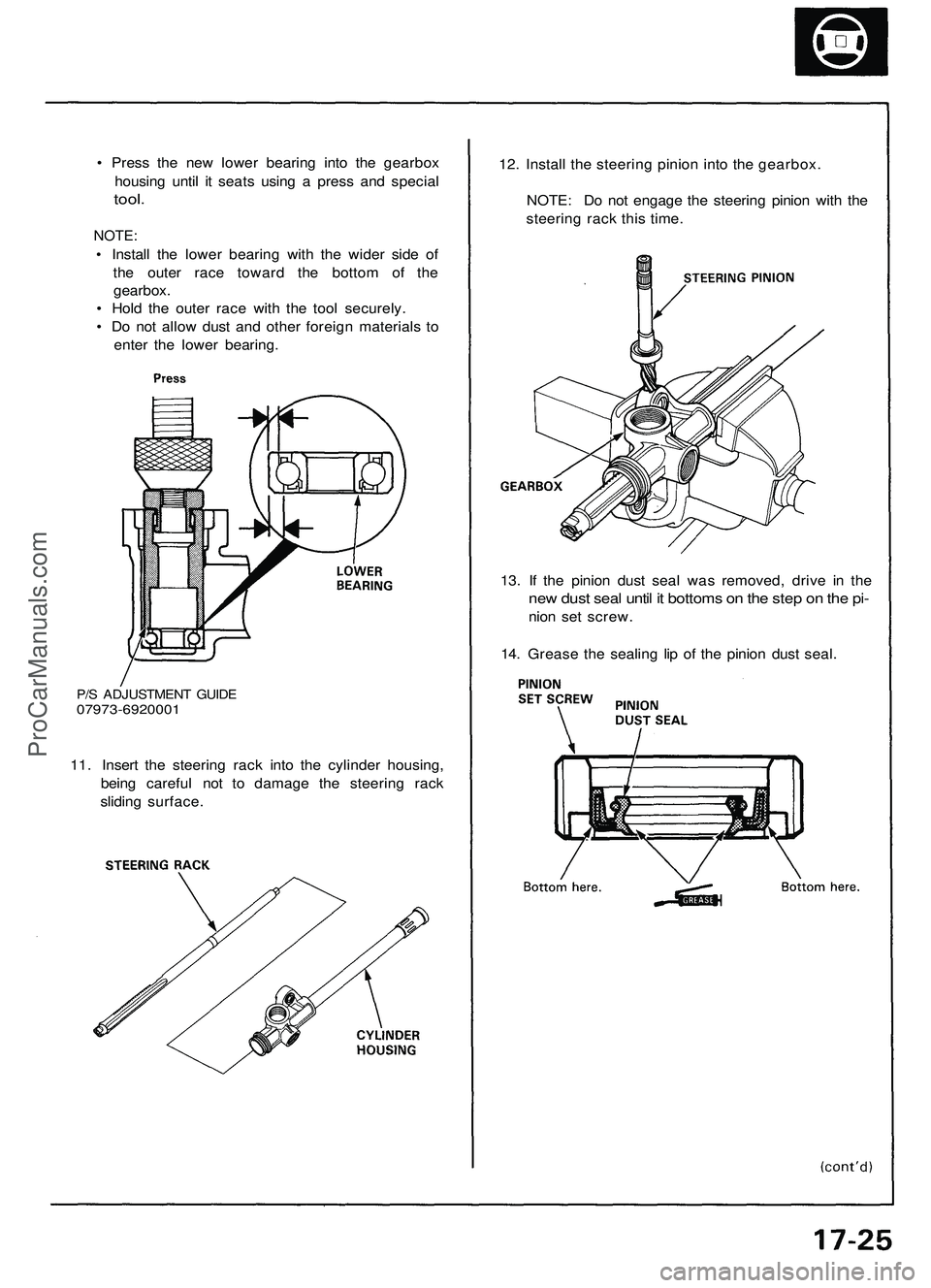
P/S ADJUSTMENT GUIDE
07973-6920001
11. Insert the steering rack into the cylinder housing,
being careful not to damage the steering rack
sliding surface.
13. If the pinion dust seal was removed, drive in the
new dust seal until it bottoms on the step on the pi-
nion set screw.
14. Grease the sealing lip of the pinion dust seal.
• Press the new lower bearing into the gearbox
housing until it seats using a press and special
tool.
NOTE:
• Install the lower bearing with the wider side of
the outer race toward the bottom of the
gearbox.
• Hold the outer race with the tool securely.
• Do not allow dust and other foreign materials to
enter the lower bearing.
12. Install the steering pinion into the gearbox.
NOTE: Do not engage the steering pinion with the
steering rack this time.ProCarManuals.com
Page 459 of 1503
Valve Seat s
Reconditionin g
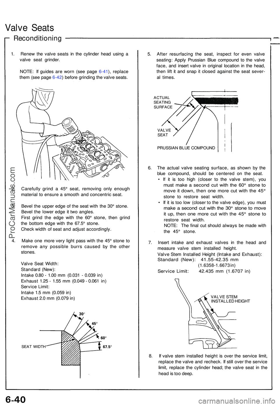
1. Rene w th e valv e seat s i n th e cylinde r hea d usin g a
valv e sea t grinder .
NOTE : I f guide s ar e wor n (se e pag e 6-41 ), replac e
the m (se e pag e 6-42 ) befor e grindin g th e valv e seats .
2 . Carefull y grin d a 45 ° seat , removin g onl y enoug h
materia l t o ensur e a smoot h an d concentri c seat .
3 . Beve l th e uppe r edg e o f th e sea t wit h th e 30 ° stone .
Beve l th e lowe r edg e i t tw o angles .
Firs t grin d th e edg e wit h th e 60 ° stone , the n grin d
th e botto m edg e wit h th e 67.5 ° stone .
Chec k widt h o f sea t an d adjus t accordingly .
4 . Mak e on e mor e ver y ligh t pas s wit h th e 45 ° ston e t o
remov e an y possibl e burr s cause d b y th e othe r
stones .
Valv e Sea t Width :
Standar d (New) :
Intak e 0.8 0 - 1.0 0 m m (0.03 1 - 0.03 9 in )
Exhaus t 1.2 5 - 1.5 5 m m (0.04 9 - 0.06 1 in )
Servic e Limit :
Intak e 1. 5 m m (0.05 9 in )
Exhaus t 2. 0 m m (0.07 9 in )
SEA T WIDT H
5. Afte r resurfacin g th e seat , inspec t fo r eve n valv e
seating : Appl y Prussia n Blu e compoun d t o th e valv e
face , an d inser t valv e i n origina l locatio n i n th e head ,
the n lif t i t an d sna p i t close d agains t th e sea t sever -
a l times .
ACTUA L
SEATIN G
SURFAC E
VALVESEAT
PRUSSIA N BLU E COMPOUN D
6. Th e actua l valv e seatin g surface , a s show n b y th e
blu e compound , shoul d b e centere d o n th e seat .
• I f i t i s to o hig h (close r t o th e valv e stem) , yo u
mus t mak e a secon d cu t wit h th e 60 ° ston e t o
mov e it down , the n on e mor e cu t wit h th e 45 °
ston e t o restor e sea t width .
• I f i t i s to o lo w (close r t o th e valv e edge) , yo u mus t
make a secon d cu t wit h th e 30 ° ston e t o mov e
it up , the n on e mor e cu t wit h th e 45 ° ston e t o
restor e sea t width .
NOTE : Th e fina l cu t shoul d alway s b e mad e wit h
th e 45 ° stone .
7 . Inser t intak e an d exhaus t valve s i n th e hea d an d
measur e valv e ste m installe d height .
Valv e Ste m Installe d Heigh t (Intak e an d Exhaust) :
Standard (New) : 41.55-42.3 5 m m
(1.6358-1.667 3 in )
Servic e Limit : 42.43 5 m m (1.670 7 in )
VALV E STE M
INSTALLE D HEIGH T
8. I f valv e ste m installe d heigh t i s ove r th e servic e limit ,
replac e th e valv e an d recheck . I f stil l ove r th e servic e
limit , replac e th e cylinde r head ; th e valv e sea t i n th e
hea d is to o deep .
ProCarManuals.com
Page 461 of 1503
Valve Guide s
Replacemen t
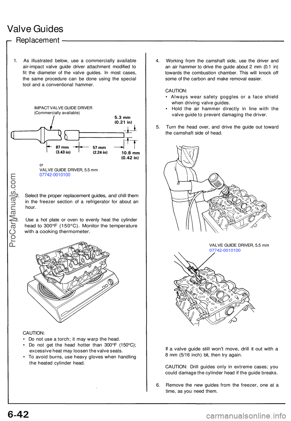
1. A s illustrate d below , us e a commerciall y availabl e
air-impac t valv e guid e drive r attachmen t modifie d t o
fi t th e diamete r o f th e valv e guides . I n mos t cases ,
th e sam e procedur e ca n b e don e usin g th e specia l
too l an d a conventiona l hammer .
IMPACT VALV E GUID E DRIVE R
(Commerciall y available )
orVALV E GUID E DRIVER , 5. 5 m m07742-0010100
2. Selec t th e prope r replacemen t guides , an d chil l the m
in th e freeze r sectio n o f a refrigerato r fo r abou t a n
hour .
3 . Us e a ho t plat e o r ove n t o evenl y hea t th e cylinde r
head t o 300° F (150°C) . Monito r th e temperatur e
with a cookin g thermometer .
CAUTION:
• D o no t us e a torch ; i t ma y war p th e head .
• D o no t ge t th e hea d hotte r tha n 30 0°F (150°C) ;
excessiv e hea t ma y loose n th e valv e seats .
• T o avoi d burns , us e heav y glove s whe n handlin g
th e heate d cylinde r head . 4
. Workin g fro m th e camshaf t side , us e th e drive r an d
a n ai r hamme r t o driv e th e guid e abou t 2 m m (0. 1 in )
toward s th e combustion chamber. Thi s wil l knoc k of f
som e o f th e carbo n an d mak e remova l easier .
CAUTION :
• Alway s wea r safet y goggle s o r a fac e shiel d
whe n drivin g valv e guides .
• Hol d th e ai r hamme r directl y i n lin e wit h th e
valv e guid e t o preven t damagin g th e driver .
5 . Tur n th e hea d over , an d driv e th e guid e ou t towar d
th e camshaf t sid e o f head .
VALV E GUID E DRIVER , 5. 5 m m07742-001010 0
If a valv e guid e stil l won' t move , dril l i t ou t wit h a
8 m m (5/1 6 inch ) bit , the n tr y again .
CAUTION : Dril l guide s onl y i n extrem e cases ; yo u
coul d damag e th e cylinde r hea d if th e guid e breaks .
6 . Remov e th e ne w guide s fro m th e freezer , on e a t a
time , a s yo u nee d them .
ProCarManuals.com
Page 464 of 1503
Valves, Valve Springs and Valve Seals
Installation Sequence
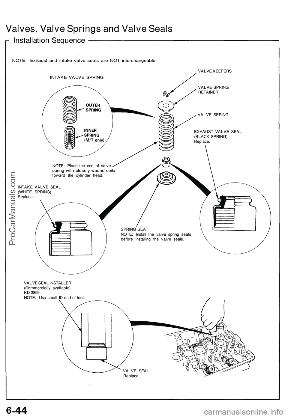
NOTE: Exhaust and intake valve seals are NOT interchangeable.
INTAKE VALVE SPRING
VALVE KEEPERS
VALVE SPRING
RETAINER
VALVE SPRING
EXHAUST VALVE SEAL
(BLACK SPRING)
Replace.
NOTE: Place the end of valve
spring with closely wound coils
toward the cylinder head.
INTAKE VALVE SEAL
(WHITE SPRING)
Replace.
SPRING SEAT
NOTE: Install the valve spring seats
before installing the valve seals.
VALVE SEAL INSTALLER
(Commercially available)
KD-2899
NOTE: Use small ID end of tool
VALVE SEAL
Replace.ProCarManuals.com
Page 1098 of 1503
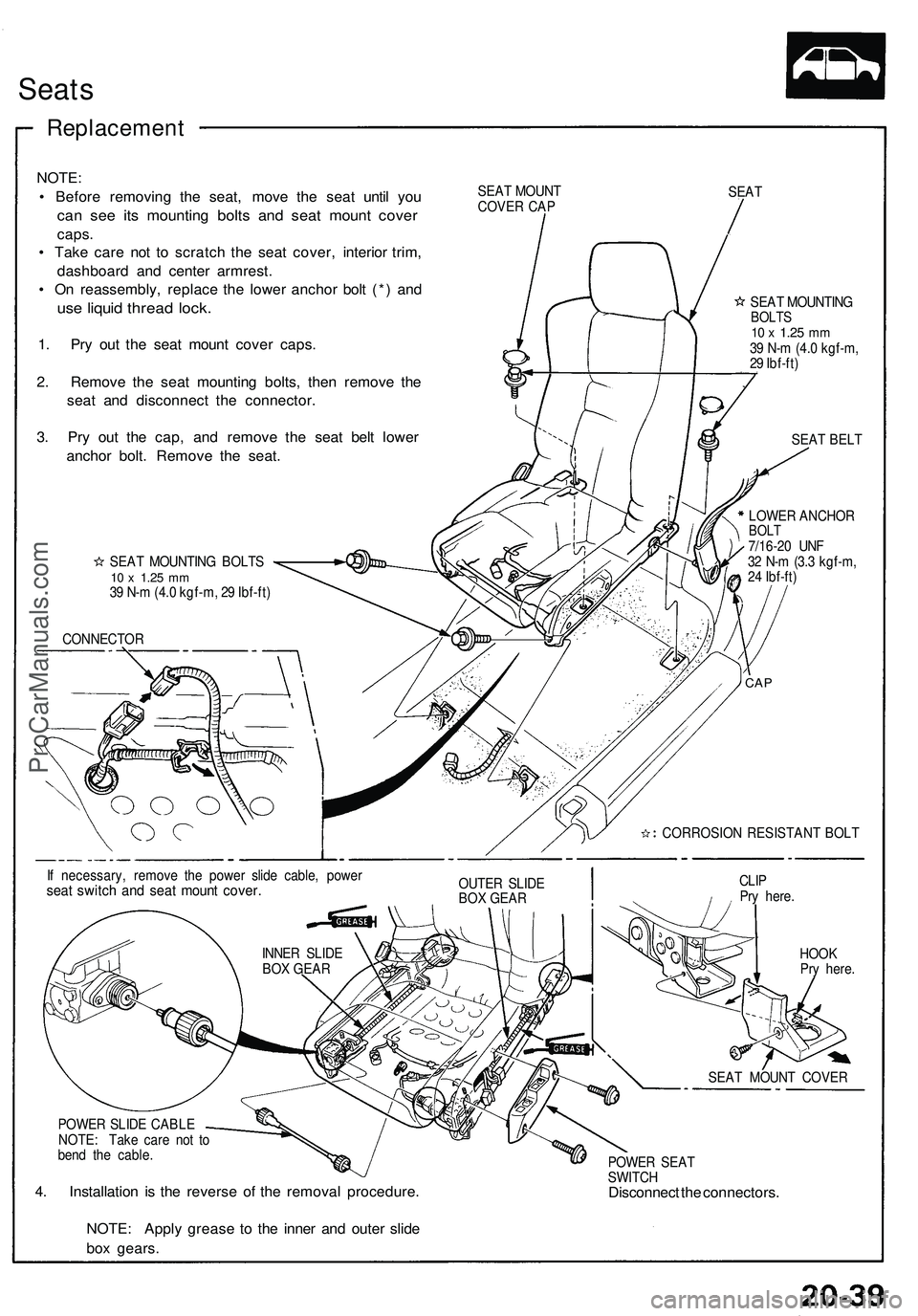
Seats
Replacemen t
NOTE:
• Befor e removin g th e seat , mov e th e sea t unti l yo u
can se e it s mountin g bolt s an d sea t moun t cove r
caps.
• Tak e car e no t t o scratc h th e sea t cover , interio r trim ,
dashboar d an d cente r armrest .
• O n reassembly , replac e th e lowe r ancho r bol t (* ) an d
use liqui d threa d lock .
1. Pr y ou t th e seat moun t cove r caps .
2 . Remov e th e sea t mountin g bolts , the n remov e th e
sea t an d disconnec t th e connector .
3 . Pr y ou t th e cap , an d remov e th e sea t bel t lowe r
ancho r bolt . Remov e th e seat .
SEAT MOUN T
COVE R CA P SEA
T
SEA T MOUNTIN G BOLT S
10 x 1.2 5 mm39 N- m (4. 0 kgf-m , 2 9 Ibf-ft )
CONNECTO R SEA
T MOUNTIN G
BOLTS10 x 1.2 5 mm39 N- m (4. 0 kgf-m ,
2 9 Ibf-ft )
SEA T BEL T
LOWE R ANCHO R
BOLT7/16-2 0 UN F
3 2 N- m (3. 3 kgf-m ,
2 4 Ibf-ft )
I f necessary , remov e th e powe r slid e cable , powe r
seat switc h an d sea t moun t cover .OUTER SLID E
BO X GEA R CLI
P
Pr y here .
HOO K
Pr y here .
POWE R SLID E CABL E
NOTE : Tak e car e no t t o
ben d th e cable .
4. Installatio n i s th e revers e o f th e remova l procedure .
POWER SEA T
SWITC H
Disconnec t th e connectors .
NOTE : Appl y greas e t o th e inne r an d oute r slid e
bo x gears .
SEAT MOUN T COVE R
CORROSIO
N RESISTAN T BOL T
CAP
INNE R SLID E
BO X GEA R
ProCarManuals.com
Page 1099 of 1503
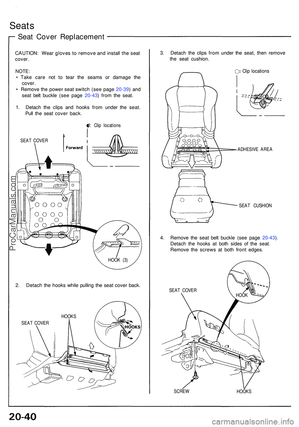
Seats
Seat Cove r Replacemen t
CAUTION: Wea r glove s t o remov e an d instal l th e sea t
cover .
NOTE :
• Tak e car e no t t o tea r th e seam s o r damag e th e
cover .
• Remov e th e powe r sea t switc h (se e pag e 20-39 ) an d
sea t bel t buckl e (se e pag e 20-43 ) fro m th e seat .
1 . Detac h th e clip s an d hook s fro m unde r th e seat .
Pul l th e sea t cove r back .
I: Cli p location s
SEA T COVE R
2. Detac h th e hook s whil e pullin g th e sea t cove r back .
SEAT COVE R
3. Detac h th e clip s fro m unde r th e seat , the n remov e
th e sea t cushion .
Clip location s
SEAT CUSHIO N
4. Remov e th e sea t bel t buckl e (se e pag e 20-43 ).
Detac h th e hook s a t bot h side s o f th e seat .
Remov e th e screw s a t bot h fron t edges .
SEAT COVE R
SCRE W
HOOKS
ADHESIV
E ARE A
HOOK S HOO
K (3 )
HOOK
ProCarManuals.com
Page 1101 of 1503
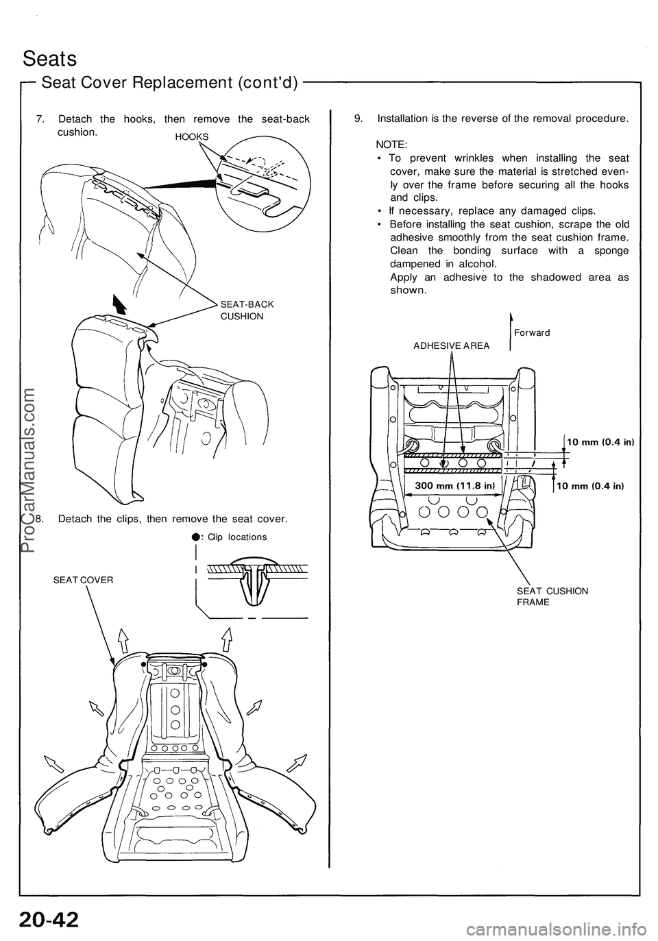
Seats
Seat Cover Replacement (cont'd)
7. Detach the hooks, then remove the seat-back
cushion.
HOOKS
8. Detach the clips, then remove the seat cover.
Clip locations
SEAT COVER
9. Installation is the reverse of the removal procedure.
NOTE:
• To prevent wrinkles when installing the seat
cover, make sure the material is stretched even-
ly over the frame before securing all the hooks
and clips.
• If necessary, replace any damaged clips.
• Before installing the seat cushion, scrape the old
adhesive smoothly from the seat cushion frame.
Clean the bonding surface with a sponge
dampened in alcohol.
Apply an adhesive to the shadowed area as
shown.
Forward
SEAT CUSHION
FRAME
SEAT-BACK
CUSHION
ADHESIVE AREAProCarManuals.com
Page 1185 of 1503
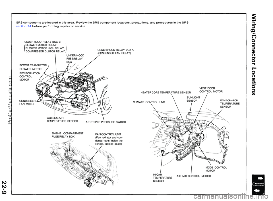
SRS component s ar e locate d in thi s area . Revie w th e SR S componen t locations , precautions , an d procedure s in th e SR S
sectio n 24 befor e performin g repair s o r service .
UNDER-HOO D RELA Y BO X BBLOWE R MOTO R RELA Y
BLOWE R MOTO R HIG H RELA Y
COMPRESSO R CLUTC H RELA Y
POWER TRANSISTO R
BLOWE R MOTO R
RECIRCULATIO N
CONTRO L
MOTO R
CONDENSE R
FA N MOTO R UNDER-HOO
D RELA Y BO X A
(CONDENSE R FA N RELAY )
HEATER COR E TEMPERATUR E SENSO R
CLIMAT E CONTRO L UNI T VEN
T DOO R
CONTRO L MOTO R
OUTSID E AI RTEMPERATUR E SENSO R
A/C TRIPL E PRESSUR E SWITC H
ENGIN E COMPARTMEN T
FUSE/RELA Y BO X
FAN CONTRO L UNI T(Fan radiato r an d con -
dense r fan s insid e th e
vehicle , behin d seats )
EVAPORATO RTEMPERATUR E
SENSO R
MOD E CONTRO L
MOTO R
IN-CA R
TEMPERATUR E
SENSO R AI
R MI X CONTRO L MOTO R
UNDER-HOO
D
FUSE/RELAYBOX
SUNLIGH TSENSOR
ProCarManuals.com
Page 1259 of 1503
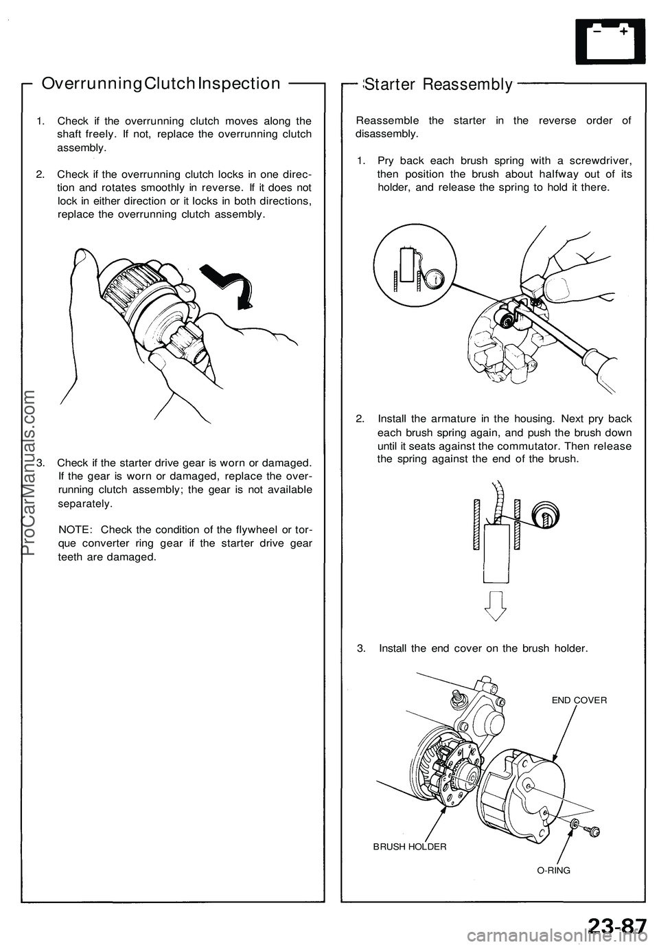
Overrunning Clutch Inspection
1. Check if the overrunning clutch moves along the
shaft freely. If not, replace the overrunning clutch
assembly.
2. Check if the overrunning clutch locks in one direc-
tion and rotates smoothly in reverse. If it does not
lock in either direction or it locks in both directions,
replace the overrunning clutch assembly.
3. Check if the starter drive gear is worn or damaged.
If the gear is worn or damaged, replace the over-
running clutch assembly; the gear is not available
separately.
NOTE: Check the condition of the flywheel or tor-
que converter ring gear if the starter drive gear
teeth are damaged.
Starter Reassembly
Reassemble the starter in the reverse order of
disassembly.
1. Pry back each brush spring with a screwdriver,
then position the brush about halfway out of its
holder, and release the spring to hold it there.
2. Install the armature in the housing. Next pry back
each brush spring again, and push the brush down
until it seats against the commutator. Then release
the spring against the end of the brush.
3. Install the end cover on the brush holder.
END COVER
BRUSH HOLDER
O-RINGProCarManuals.com
Page 1422 of 1503
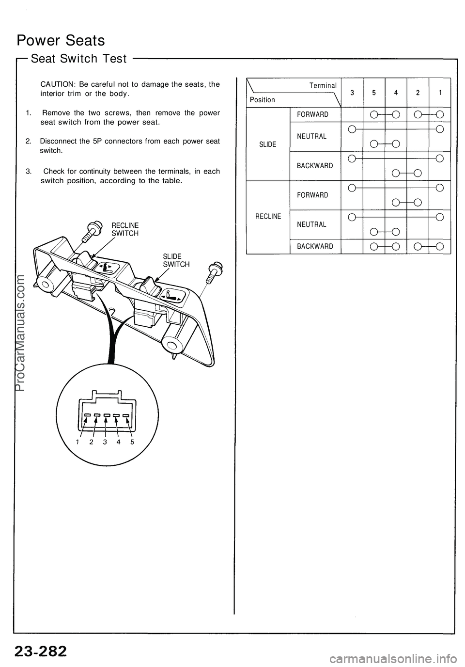
Power Seats
Seat Switch Test
CAUTION: Be careful not to damage the seats, the
interior trim or the body.
1. Remove the two screws, then remove the power
seat switch from the power seat.
2. Disconnect the 5P connectors from each power seat
switch.
3. Check for continuity between the terminals, in each
switch position, according to the table.
RECLINE
SWITCH
SLIDE
SWITCH
SLIDE
RECLINE
Position
Terminal
FORWARD
NEUTRAL
BACKWARD
FORWARD
NEUTRAL
BACKWARDProCarManuals.com