alternator belt ACURA NSX 1997 Service Repair Manual
[x] Cancel search | Manufacturer: ACURA, Model Year: 1997, Model line: NSX, Model: ACURA NSX 1997Pages: 1503, PDF Size: 57.08 MB
Page 375 of 1503

4-6
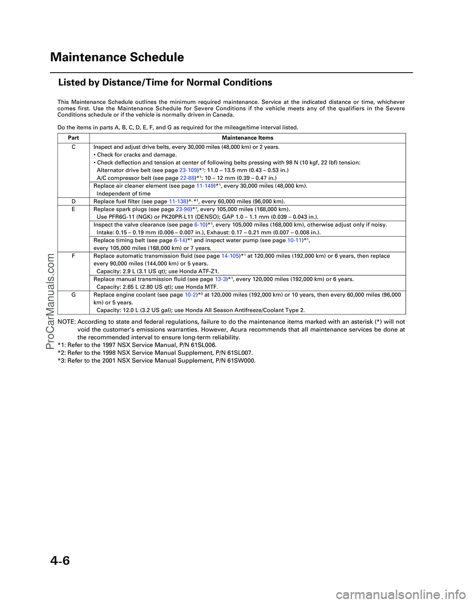
This Maintenance Schedule outlines the minimum required maintenance. Ser\
vice at the indicated distance or time, whichever
comes first. Use the Maintenance Schedule for Severe Conditions if the v\
ehicle meets any of the qualifiers in the Severe
Conditions schedule or if the vehicle is normally driven in Canada.
Do the items in parts A, B, C, D, E, F, and G as required for the mileag\
e/time interval listed.
NOTE: According to state and federal regulations, failure to do the maintenanc\
e items marked with an asterisk (*) will not
void the customer ’s emissions warranties. However, Acura recommends that all maintenance s\
ervices be done at
the recommended interval to ensure long-term reliability.
*1: Refer to the 1997 NSX Service Manual, P/N 61SL006.
*2: Refer to the 1998 NSX Service Manual Supplement, P/N 61SL007.
*3: Refer to the 2001 NSX Service Manual Supplement, P/N 61SW000.
C
D
E
F
G Inspect and adjust drive belts, every 30,000 miles (48,000 km) or 2 ye\
ars.
•
Check for cracks and damage.
• Check deflection and tension at center of following belts pressing with\
98 N (10 kgf, 22 lbf) tension:
Alternator drive belt (see page 23-109)*
1: 11.0 – 13.5 mm (0.43 – 0.53 in.)
A/C compressor belt (see page 22-88)*1: 10 – 12 mm (0.39 – 0.47 in.)
Replace air cleaner element (see page 11-149)*1, every 30,000 miles (48,000 km).
Independent of time
Replace fuel filter (see page 11-138)*, *1, every 60,000 miles (96,000 km).
Replace spark plugs (see page 23-96)*1, every 105,000 miles (168,000 km).
Use PFR6G-11 (NGK) or PK20PR-L11 (DENSO); GAP 1.0 – 1.1 mm (0.039 – 0.043 in.).
Inspect the valve clearance (see page 6-10)*1, every 105,000 miles (168,000 km), otherwise adjust only if noisy.
Intake: 0.15 – 0.19 mm (0.006 – 0.007 in.), Exhaust: 0.17 – 0.21 mm (0.007 – 0.008 in.).
Replace timing belt (see page 6-14)*1 and inspect water pump (see page 10-11)*1,
every 105,000 miles (168,000 km) or 7 years.
Replace automatic transmission fluid (see page 14-105)*1 at 120,000 miles (192,000 km) or 6 years, then replace
every 90,000 miles (144,000 km) or 5 years.
Capacity: 2.9 L (3.1 US qt); use Honda ATF-Z1.
Replace manual transmission fluid (see page 13-3)*1, every 120,000 miles (192,000 km) or 6 years.
Capacity: 2.65 L (2.80 US qt); use Honda MTF.
Replace engine coolant (see page 10-2 )*3 at 120,000 miles (192,000 km) or 10 years, then every 60,000 miles (9\
6,000
km) or 5 years. Capacity: 12.0 L (3.2 US gal); use Honda All Season Antifreeze/Coolant\
Type 2.
Part Maintenance Items
Maintenance Schedule
Listed by Distance/Time for Normal Conditions
*05-NSX (61SW004)SEC04(01-10) 9/22/04 1:49 PM Page 4-6
ProCarManuals.com
Page 433 of 1503

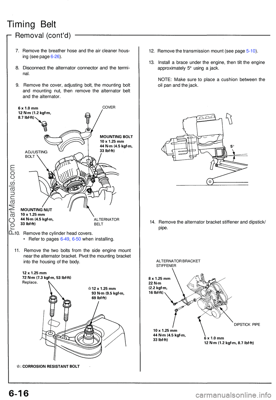
Timing Bel t
Remova l (cont'd )
7. Remov e th e breathe r hos e an d th e ai r cleaner hous-
in g (se e pag e 6-26 ).
8 . Disconnec t th e alternato r connecto r an d th e termi -
nal.
9. Remov e th e cover , adjustin g bolt , th e mountin g bol t
an d mountin g nut , the n remov e th e alternato r bel t
an d th e alternator .
COVER
ADJUSTIN GBOLT
ALTERNATO RBELT
12. Remov e th e transmissio n moun t (se e pag e 5-10 ).
13 . Instal l a brac e unde r th e engine , the n til t th e engin e
approximatel y 5 ° usin g a jack .
NOTE : Mak e sur e t o plac e a cushio n betwee n th e
oi l pa n an d th e jack .
14 . Remov e th e alternato r bracke t stiffene r an d dipstick /
pipe .
ALTERNATO R BRACKE TSTIFFENE R
DIPSTICK PIP E
10. Remov e th e cylinde r hea d covers .
• Refe r t o page s 6-49 , 6-5 0 whe n installing .
11 . Remov e th e tw o bolt s fro m th e sid e engin e moun t
nea r th e alternato r bracket . Pivo t th e mountin g bracke t
int o th e housin g o f th e body .
ProCarManuals.com
Page 445 of 1503

Cylinder Head s
Remova l (cont'd )
26. Remov e th e engin e wir e harnes s connector s an d
wir e harnes s clamp s fro m th e cylinde r hea d an d
intak e manifold .
• Si x injecto r connector s
• Intak e ai r temperatur e (IAT ) senso r connecto r
• CKP/CY P senso r connecto r
• Heate d oxyge n senso r (HO2S ) connector s
• Ignitio n contro l modul e (ICM ) connector s
• Engin e coolan t temperatur e (ECT ) senso r connec -
tor
• Coolan t temperatur e gaug e sendin g uni t connec -
tor
• Radiato r fa n contro l senso r connecto r
• Exhaust gas recirculatio n (EGR ) valv e lift senso r
connecto r
• Throttl e positio n senso r connecto r
• Engin e oi l pressur e gaug e sendin g uni t connecto r
• Knoc k senso r connecto r
• VTE C solenoi d valv e connector s
• VTE C pressur e switc h connector s
• Engin e oi l pressur e switc h connecto r
• Alternato r connecto r
• Alternato r termina l
• Throttl e bod y 6 P connecto r
27 . Remov e th e ignitio n coil s an d connector .
28 . Remov e th e EG R pip e an d intak e manifol d assem -
bly.
GASKET SReplace.
INTAKEMANIFOL DASSEMBL Y
GASKETReplace .
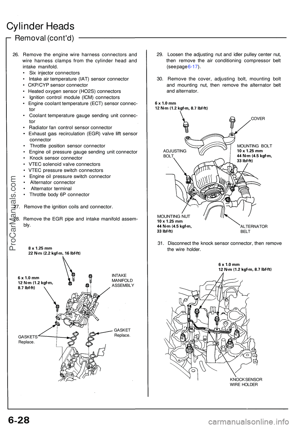
29. Loose n th e adjustin g nu t an d idle r pulle y cente r nut ,
the n remov e th e ai r conditionin g compresso r bel t
(se e pag e 6-17 ).
30 . Remov e th e cover , adjustin g bolt , mountin g bol t
an d mountin g nut , the n remov e th e alternato r bel t
an d alternator .
COVER
ADJUSTIN GBOLT
MOUNTIN G BOL T
MOUNTIN G NU T
ALTERNATO RBELT
31. Disconnec t th e knoc k senso r connector , the n remov e
th e wir e holder .
KNOCK SENSO RWIRE HOLDE R
ProCarManuals.com
Page 1231 of 1503

Troubleshooting
Tips and Precautions
Before Troubleshooting
Check applicable fuses in the appropriate fuse box.
Check the battery for damage, state of charge, and
clean and tight connections.
Check the alternator belt tension.
CAUTION:
Do not quick-charge a battery unless the battery
ground cable has been disconnected.
Otherwise you will damage the alternator
diodes.
Do not attempt to crank the engine with the bat-
tery ground cable loosely connected or you will
severely damage the wiring.
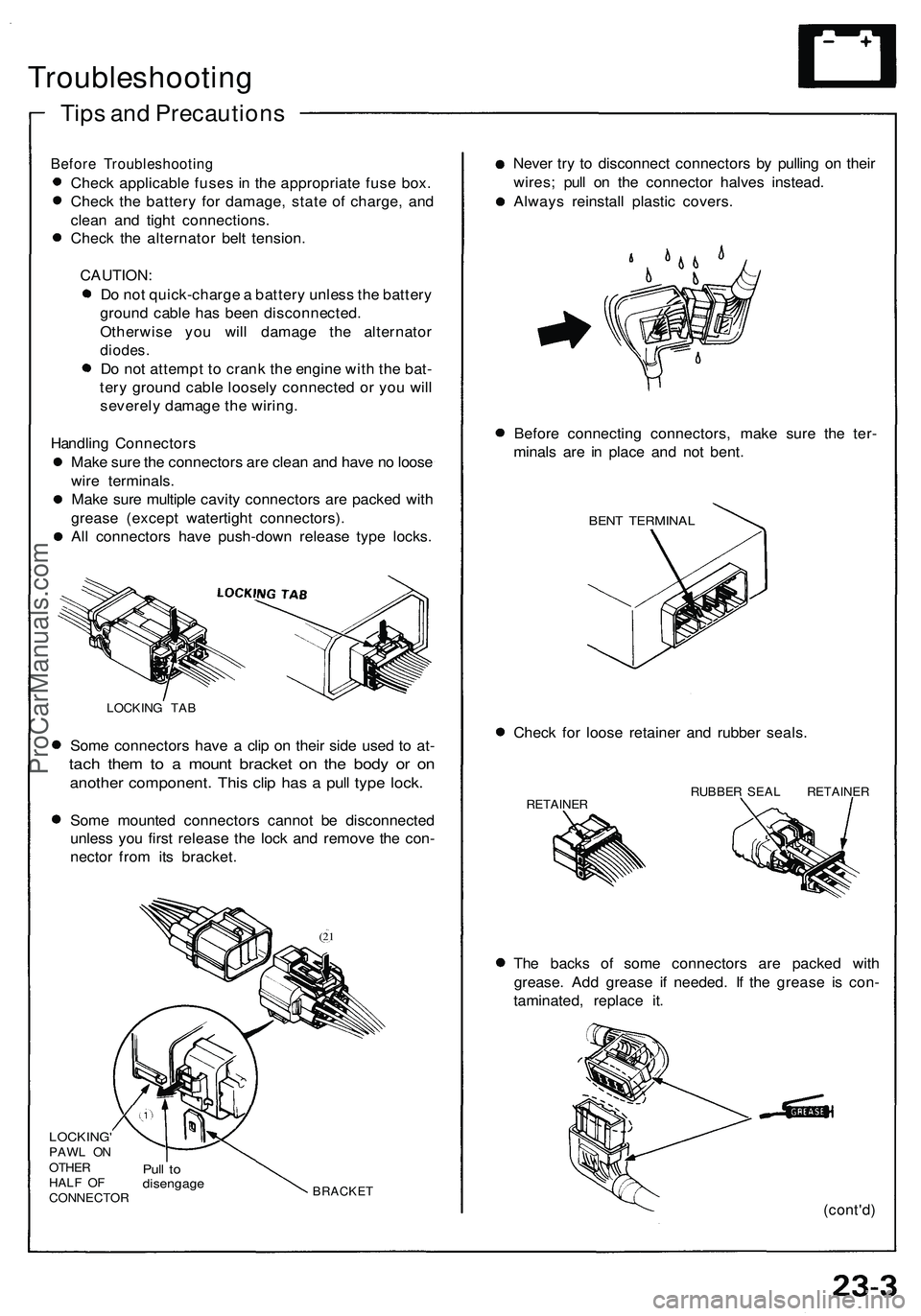
Handling Connectors
Make sure the connectors are clean and have no loose
wire terminals.
Make sure multiple cavity connectors are packed with
grease (except watertight connectors).
All connectors have push-down release type locks.
LOCKING TAB
Some connectors have a clip on their side used to at-
tach them to a mount bracket on the body or on
another component. This clip has a pull type lock.
Some mounted connectors cannot be disconnected
unless you first release the lock and remove the con-
nector from its bracket.
(21
LOCKING'
PAWL ON
OTHER
HALF OF
CONNECTOR
Pull to
disengage
BRACKET
Never try to disconnect connectors by pulling on their
wires; pull on the connector halves instead.
Always reinstall plastic covers.
Before connecting connectors, make sure the ter-
minals are in place and not bent.
BENT TERMINAL
Check for loose retainer and rubber seals.
RETAINER
RUBBER SEAL RETAINER
The backs of some connectors are packed with
grease. Add grease if needed. If the grease is con-
taminated, replace it.
(cont'd)ProCarManuals.com
Page 1279 of 1503

Alternator Bel t Adjustmen t
Deflection Method :
1 . Appl y a forc e o f 9 8 N (1 0 kgf , 2 2 Ibf ) betwee n th e
alternato r an d crankshaf t pulley , an d measur e it s
deflection .
Deflection : 11-13. 5 m m (0.43-0.5 3 in )
NOTE : O n a brand-ne w belt , th e deflectio n shoul d
be 6- 8 m m (0.24-0.3 1 in ) befor e th e bel t ha s
had an y runnin g tim e o n th e engine .
ADJUSTIN G BOL T8 N- m (0. 8 kgf-m , 5. 8 Ibf-ft )
MOUNTIN G BOL T45 N- m (4. 6 kgf-m , 3 3 Ibf-ft )
ADJUSTMENT-LOC KNUT45 N- m (4. 6 kgf-m , 3 3 Ibf-ft )CRANKSHAF T PULLE Y
2. I f bel t deflectio n i s incorrect , loose n th e
adjustment-loc k nu t an d th e mountin g bolt .
3 . Tur n th e adjustin g bol t unti l bel t deflectio n i s cor -
rect , the n retighte n th e nu t an d bolt .
4 . Rechec k th e bel t tension . Tensio
n Gaug e Method :
1 . Attac h th e bel t tensio n gaug e t o th e belt , an d mea -
sur e bel t tension .
Tension : 45 0 - 65 0 N (4 5 - 6 5 kgf , 99-14 3 Ibf )
NOTE : O n a brand-ne w belt , th e tensio n shoul d b e
90 0 - 110 0 N (9 0 - 11 0 kgf , 19 8 - 24 3 Ibf ) befor e th e
bel t ha s ha d an y runnin g tim e o n th e engine .
MOUNTIN G BOL T45 N- m (4. 6 kgf-m , 3 3 Ibf-ft )
ADJUSTIN G BOL T8 N- m (0. 8 kgf-m , 5. 8 Ibf-ft )BELT TENSIO N GAUG E07JGG-001010 A
ADJUSTMENT-LOC KNUT45 N- m (4. 6 kgf-m ,33 Ibf-ft )CRANKSHAF T PULLE Y
2. I f bel t tensio n i s incorrect , loose n th e adjustment -
loc k nu t an d th e mountin g bolt .
3 . Tur n th e adjustin g bol t unti l bel t tensio n i s correct ,
the n retighte n th e nu t an d bolt .
4 . Rechec k th e bel t tension .
ProCarManuals.com