oil change ACURA NSX 1997 Service Repair Manual
[x] Cancel search | Manufacturer: ACURA, Model Year: 1997, Model line: NSX, Model: ACURA NSX 1997Pages: 1503, PDF Size: 57.08 MB
Page 31 of 1503
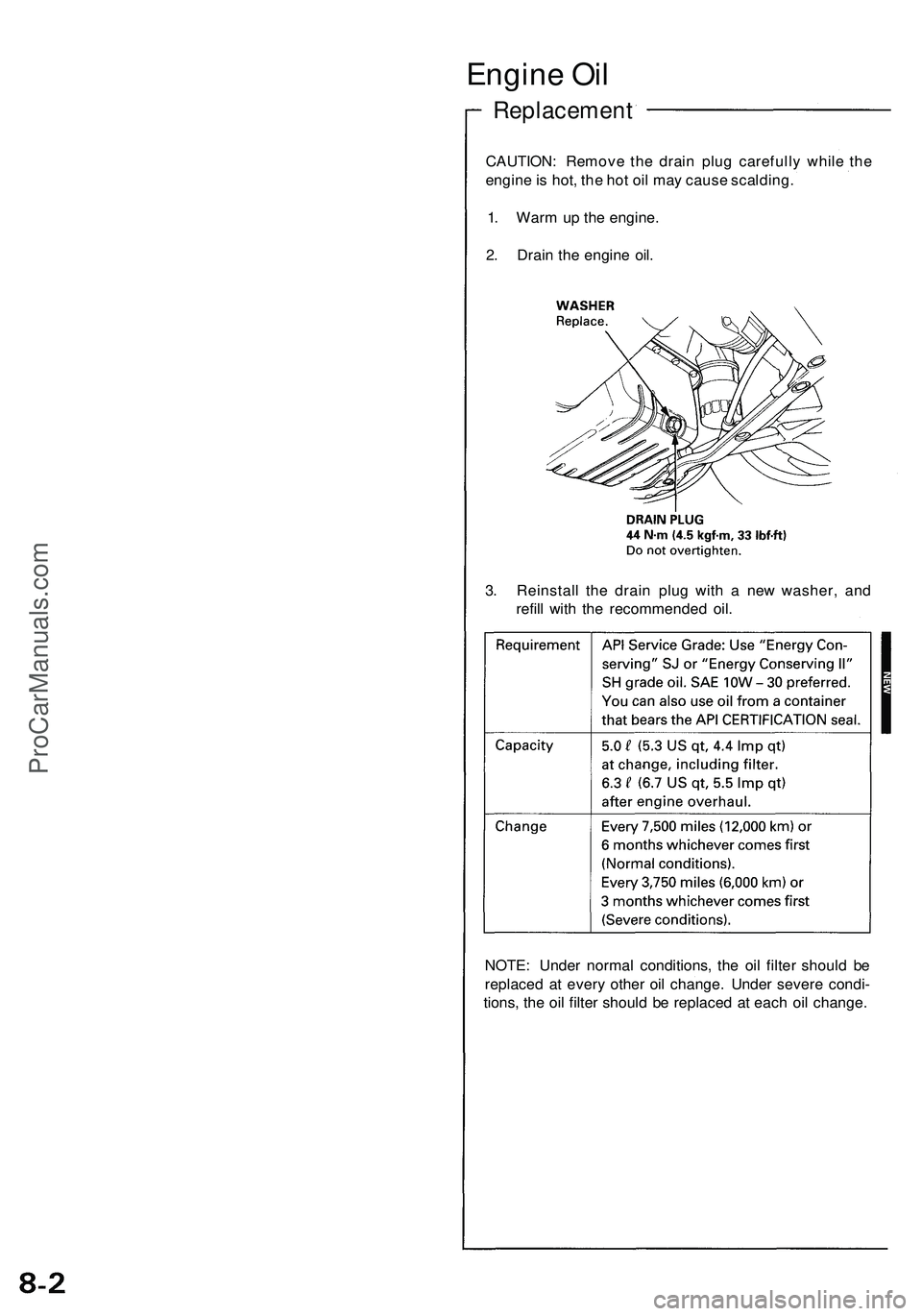
Engine Oi l
Replacemen t
CAUTION: Remov e th e drai n plu g carefull y whil e th e
engin e is hot , th e ho t oi l ma y caus e scalding .
1 . War m u p th e engine .
2 . Drai n th e engin e oil .
3 . Reinstal l th e drai n plu g wit h a ne w washer , an d
refil l wit h th e recommende d oil .
NOTE : Unde r norma l conditions , th e oi l filte r shoul d b e
replace d a t ever y othe r oi l change . Unde r sever e condi -
tions , th e oi l filte r shoul d b e replace d a t eac h oi l change .
ProCarManuals.com
Page 371 of 1503
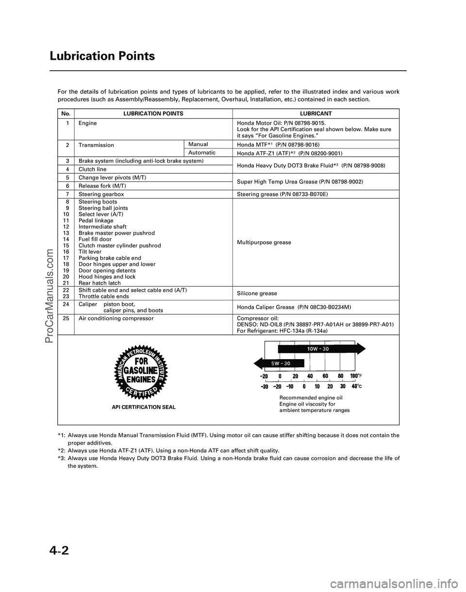
4-2
For the details of lubrication points and types of lubricants to be appl\
ied, refer to the illustrated index and various work
procedures (such as Assembly/Reassembly, Replacement, Overhaul, Install\
ation, etc.) contained in each section.
*1: Always use Honda Manual Transmission Fluid (MTF). Using motor oil can \
cause stiffer shifting because it does not contain theproper additives.
*2: Always use Honda ATF-Z1 (ATF). Using a non-Honda ATF can affect shift \
quality.
*3: Always use Honda Heavy Duty DOT3 Brake Fluid. Using a non-Honda brake fl\
uid can cause corrosion and decrease the life of the system.
Lubrication Points
No.LUBRICATION POINTSLUBRICANT
1Honda Motor Oil: P/N 08798-9015.
Look for the API Certification seal shown below. Make sure
it says “For Gasoline Engines.”
2TransmissionHonda MTF*1(P/N 08798-9016)
3Brake system (including anti-lock brake system)Honda Heavy Duty DOT3 Brake Fluid*3(P/N 08798-9008)4Clutch line
5Change lever pivots (M/T)Super High Temp Urea Grease (P/N 08798-9002)6Release fork (M/T)
8
9
10
11
12
13
14
15
16
17
18
19
20
21Steering boots
Steering ball joints
Select lever (A/T)
Pedal linkage
Intermediate shaft
Brake master power pushrod
Fuel fill door
Clutch master cylinder pushrod
Tilt lever
Parking brake cable end
Door hinges upper and lower
Door opening detents
Hood hinges and lock
Rear hatch latch
Multipurpose grease
24
22
23
Caliper piston boot, caliper pins, and boots
Shift cable end and select cable end (A/T)
Throttle cable ends
Honda Caliper Grease (P/N 08C30-B0234M)
Silicone grease
25Air conditioning compressorCompressor oil:
DENSO: ND-OIL8 (P/N 38897-PR7-A01AH or 38899-PR7-A01)
For Refrigerant: HFC-134a (R-134a)
Manual
Honda ATF-Z1 (ATF)*2(P/N 08200-9001)Automatic
7Steering gearboxSteering grease (P/N 08733-B070E)
Engine
API CERTIFICATION SEAL
Recommended engine oil
Engine oil viscosity for
ambient temperature ranges
*05-NSX (61SW004)SEC04(01-10) 9/22/04 1:49 PM Page 4-2
ProCarManuals.com
Page 464 of 1503
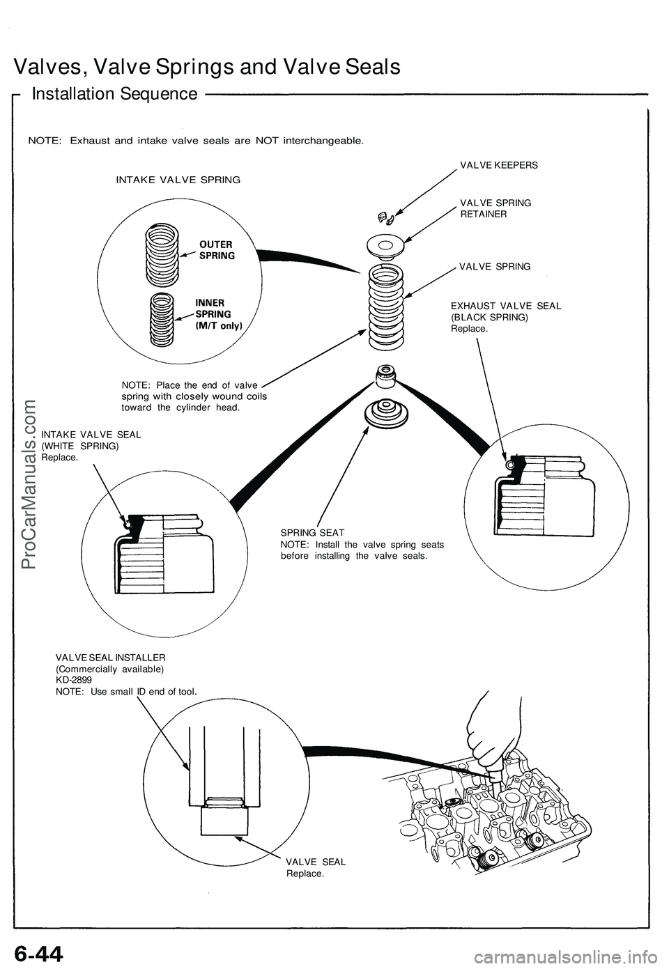
Valves, Valve Springs and Valve Seals
Installation Sequence
NOTE: Exhaust and intake valve seals are NOT interchangeable.
INTAKE VALVE SPRING
VALVE KEEPERS
VALVE SPRING
RETAINER
VALVE SPRING
EXHAUST VALVE SEAL
(BLACK SPRING)
Replace.
NOTE: Place the end of valve
spring with closely wound coils
toward the cylinder head.
INTAKE VALVE SEAL
(WHITE SPRING)
Replace.
SPRING SEAT
NOTE: Install the valve spring seats
before installing the valve seals.
VALVE SEAL INSTALLER
(Commercially available)
KD-2899
NOTE: Use small ID end of tool
VALVE SEAL
Replace.ProCarManuals.com
Page 502 of 1503
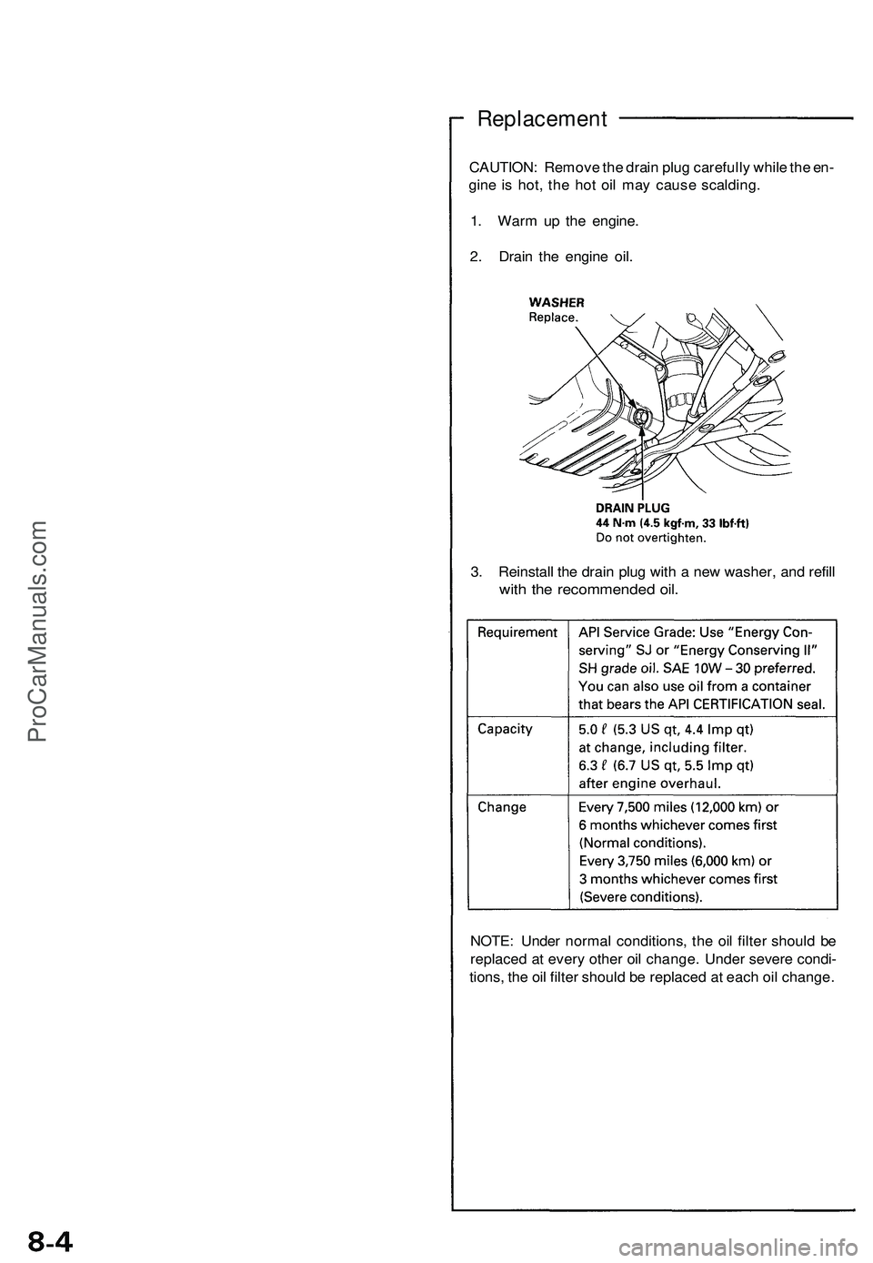
Replacement
CAUTION: Remove the drain plug carefully while the en-
gine is hot, the hot oil may cause scalding.
1. Warm up the engine.
2. Drain the engine oil.
3. Reinstall the drain plug with a new washer, and refill
with the recommended oil.
NOTE: Under normal conditions, the oil filter should be
replaced at every other oil change. Under severe condi-
tions, the oil filter should be replaced at each oil change.ProCarManuals.com
Page 652 of 1503
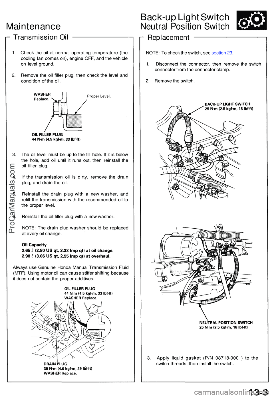
Maintenance
Transmissio n Oi l
1. Chec k th e oi l a t norma l operating temperatur e (th e
coolin g fa n come s on) , engin e OFF , an d th e vehicl e
o n leve l ground .
2 . Remov e th e oi l fille r plug , the n chec k th e leve l an d
conditio n o f th e oil .
3. Th e oi l leve l mus t b e u p t o th e fil l hole . I f i t i s belo w
th e hole , ad d oi l unti l i t run s out , the n reinstal l th e
oi l fille r plug .
4 . I f th e transmissio n oi l i s dirty , remov e th e drai n
plug , an d drai n th e oil .
5 . Reinstal l th e drai n plu g wit h a ne w washer , an d
refil l th e transmissio n wit h th e recommende d oi l t o
th e prope r level .
6 . Reinstal l th e oi l fille r plu g wit h a ne w washer .
NOTE : Th e drai n plu g washe r shoul d b e replace d
a t ever y oi l change .
Back-up Ligh t Switc h
Neutra l Positio n Switc h
Replacemen t
NOTE: T o chec k th e switch , se e sectio n 23 .
1 . Disconnec t th e connector , the n remov e th e switc h
connecto r fro m th e connecto r clamp .
2 . Remov e th e switch .
3 . Appl y liqui d gaske t (P/ N 0871 8-0001 ) t o th e
switc h threads , the n instal l th e switch .
Alway
s us e Genuin e Hond a Manua l Transmissio n Flui d
(MTF) . Usin g moto r oi l ca n caus e stiffe r shiftin g becaus e
i t doe s no t contai n th e prope r additives .
ProCarManuals.com
Page 713 of 1503
Description
The automatic transmission is a combination of a 3-element torque converter and a triple-shaft electronically controlled
automatic transmission which provides 4 speeds forward and 1 speed reverse. The entire unit is positioned in line with the
engine.
Torque Converter, Gears, and Clutches
The torque converter consists of a pump, turbine, and stator, assembled in a single unit.
They are connected to the engine crankshaft so they turn together as a unit as the engine turns.
Around the outside of the torque converter is a ring gear which meshes with the starter pinion when the engine is being
started. The entire torque converter assembly serves as a flywheel while transmitting power to the transmission main-
shaft. The transmission has three parallel shafts: the mainshaft, the countershaft, and the secondary shaft. The mainshaft
is in line with the engine crankshaft.
The mainshaft includes the 1st and 4th clutches, and gears for 3rd, 4th, reverse, and 1st (3rd gear is integral with the main-
shaft, while reverse gear is integral with 4th gear).
The countershaft includes the 1st-hold and 3rd clutches, and gears for 2nd, 3rd, 4th, reverse, 1st, and parking.
The secondary shaft includes the 2nd clutch and gears for 2nd and 3rd.
The 4th and reverse gears can be locked to the countershaft at its center, providing 4th gear or reverse, depending on
which way the selector is moved.
The gears on the mainshaft and secondary shaft are in constant mesh with those on the countershaft.
When certain combinations of gears in the transmission are engaged by clutches, power is transmitted from the mainshaft
to the countershaft to provide positions.
Electronic Control
The electronic control system consists of the Transmission Control Module (TCM), sensors, a linear solenoid, a shift switch,
and 4 solenoid valves. Shifting and lock-up are electronically controlled for comfortable driving under all conditions.
The TCM is located on the insulator center bulkhead, behind the driver's seat.
Hydraulic Control
The valve bodies include the main valve body, secondary valve body, servo body, regulator valve body, throttle valve
body, lock-up valve body, and the 2nd accumulator body.
They are bolted to the torque converter housing as an assembly.
The main valve body contains the manual valve, 1-2 shift valve, 2-3 shift valve, 3-4 shift valve, relief valve, one-way relief
valve, and oil pump gears.
The secondary valve body contains the 3-2 kick-down valve, clutch pressure control (CPC) valve, 2nd orifice control valve, 3rd
orifice control valve, modulator valve, 4th exhaust valve, servo control valve, 2nd exhaust valve, and 4-3 kick-down valve.
The servo body contains the accumulator pistons and servo valve. The throttle valve body includes the throttle valve B
which is bolted to the servo body.
The regulator valve body contains the pressure regulator valve, lock-up control valve, and cooler relief valve. Fluid from
the regulator passes through the manual valve to the various control valves.
The lock-up valve body contains the lock-up timing B valve and lock-up shift valve. The 2nd accumulator body contains
the accumulator pistons and limited slip differential relief valve.
The torque converter check valve is located in the torque converter housing, under the main valve body.
The 1st, 1st-hold, 3rd, and 4th clutches receive fluid from their respective feed pipes and the 2nd clutch receives fluid from
the internal hydraulic circuit.
Shift Control Mechanism
Input from various sensors located throughout the vehicle determines which shift control solenoid valve the TCM will acti-
vate. Activating a shift control solenoid valve changes modulator pressure, causing a shift valve to move. This pressurizes
a line to one of the clutches, engaging that clutch and its corresponding gear.
Lock-up Mechanism
In position and position in 2nd, 3rd, and 4th, pressurized fluid is drained from the back of the torque converter
through a fluid passage, causing the lock-up piston to be held against the torque converter cover. As this takes place, the
mainshaft rotates at the same speed as the engine crankshaft. Together with hydraulic control, the TCM optimizes the tim-
ing of the lock-up mechanism.
The lock-up valves control the range of lock-up according to lock-up control solenoid valves A and B, and throttle valve B.
When lock-up control solenoid valves A and B activate, modulator pressure changes. The lock-up control solenoid valves
A and B are mounted on the torque converter housing, and are controlled by the TCM.
(cont'd)ProCarManuals.com
Page 899 of 1503
System Description
Function and Operation
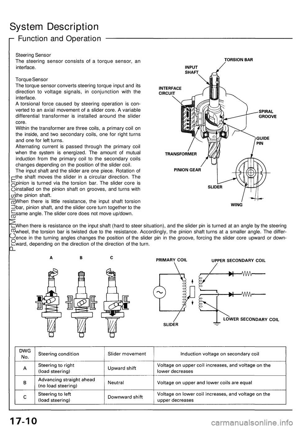
Steering Sensor
The steering sensor consists of a torque sensor, an
interface.
Torque Sensor
The torque sensor converts steering torque input and its
direction to voltage signals, in conjunction with the
interface.
A torsional force caused by steering operation is con-
verted to an axial movement of a slider core. A variable
differential transformer is installed around the slider
core.
Within the transformer are three coils, a primary coil on
the inside, and two secondary coils, one for right turns
and one for left turns.
Alternating current is passed through the primary coil
when the system is energized. The amount of mutual
induction from the primary coil to the secondary coils
changes depending on the position of the slider coil.
The input shaft and the slider are one piece. Rotation of
the shaft moves the slider in a circular direction. The
pinion is turned via the torsion bar. The slider core is
installed on the pinion shaft on grooves, and turns with
the pinion shaft.
When there is little resistance, the input shaft torsion
bar, pinion shaft, and the slider core turn together to the
same angle. The slider core does not move up/down.
When there is resistance on the input shaft (hard to steer situation), and the slider pin is turned at an angle by the steering
wheel, the torsion bar is twisted due to the resistance. Accordingly, the pinion shaft turns at a smaller angle. The differ-
ence in the turning angles changes the position of the slider pin in the groove, forcing the slider core upward or down-
ward, depending on the direction of the direction of the turn.ProCarManuals.com
Page 1222 of 1503
Clutch Inspectio n
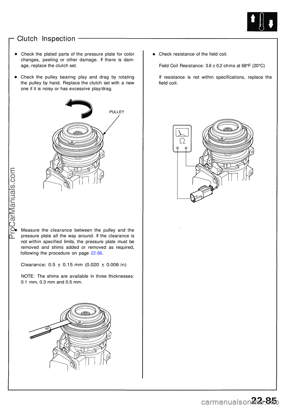
Check th e plate d part s o f th e pressur e plat e fo r colo r
changes , peelin g o r othe r damage . I f ther e i s dam -
age , replac e th e clutc h set .
Chec k th e pulle y bearin g pla y an d dra g b y rotatin g
th e pulle y b y hand . Replac e th e clutc h se t wit h a ne w
on e i f i t i s nois y o r ha s excessiv e play/drag .
PULLEY
Measur e th e clearanc e betwee n th e pulle y an d th e
pressur e plat e al l th e wa y around . I f th e clearanc e i s
no t withi n specifie d limits , th e pressur e plat e mus t b e
remove d an d shim s adde d o r remove d a s required ,
followin g th e procedur e o n pag e 22-86 .
Clearance : 0. 5 ± 0.1 5 m m (0.02 0 ± 0.00 6 in )
NOTE : Th e shim s ar e availabl e i n thre e thicknesses :
0.1 mm , 0. 3 m m an d 0. 5 mm .
Chec k resistanc e o f th e fiel d coil .
Fiel d Coi l Resistance : 3. 6 ± 0. 2 ohm s a t 68° F (20°C )
I f resistanc e i s no t withi n specifications , replac e th e
field coil .
ProCarManuals.com