bolt pattern ACURA NSX 1997 Service Repair Manual
[x] Cancel search | Manufacturer: ACURA, Model Year: 1997, Model line: NSX, Model: ACURA NSX 1997Pages: 1503, PDF Size: 57.08 MB
Page 385 of 1503
Service Precautions
Handling of Special Nuts and Bolts
Handling of Tires
• The tires on NSX & NSX-T should not be rotated. The
front wheels are 16" in, diameter and the rear wheels
are 17" in, so they cannot be rotated front-to-rear.
The original-equipment tires on NSX & NSX-T have a
unidirectional tread pattern, so they cannot be rotat-
ed side-to-side.
• The folding spare tire cannot be repaired or removed
from the rim.
Engine Steam-cleaning
(NSX-T only)
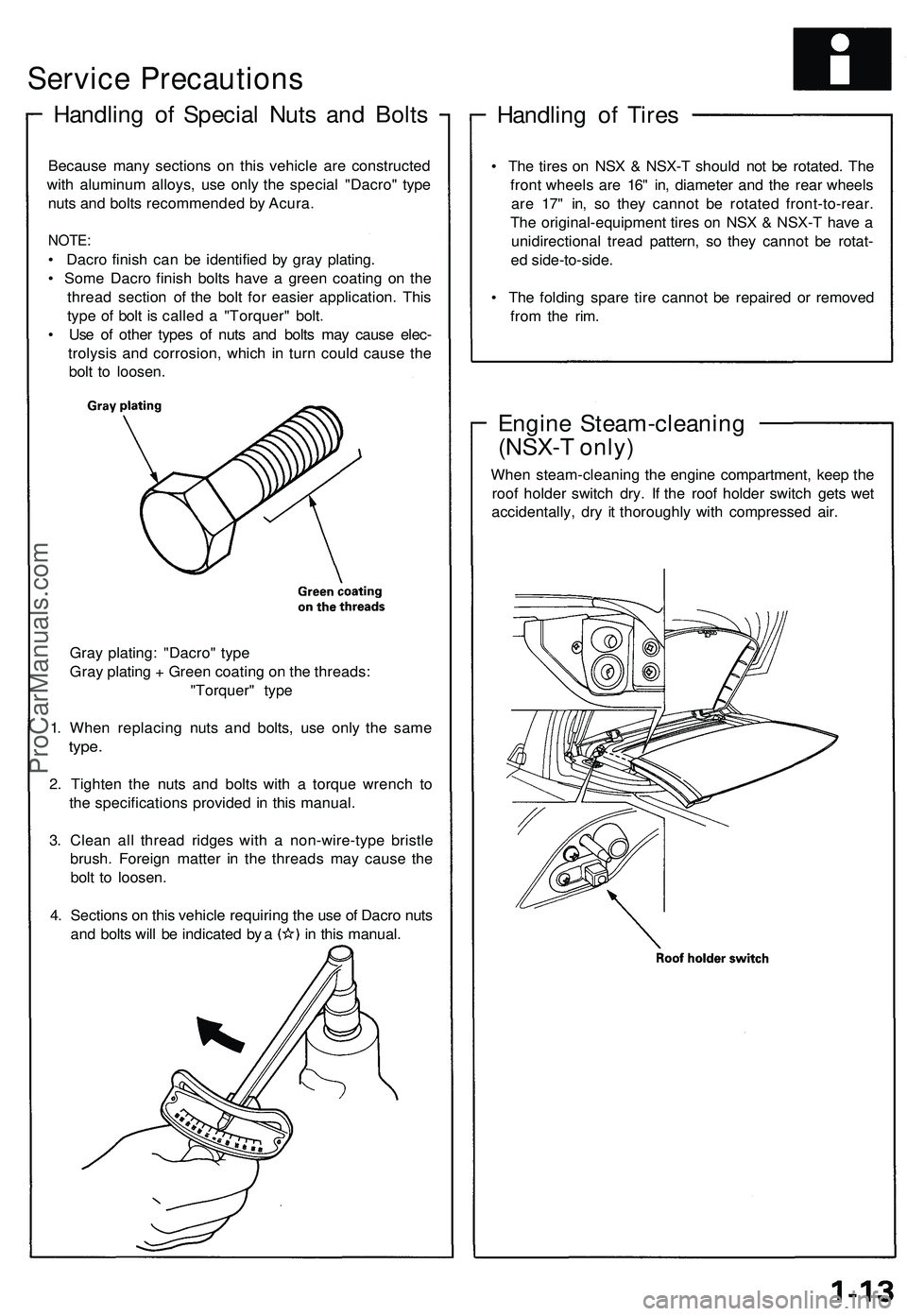
When steam-cleaning the engine compartment, keep the
roof holder switch dry. If the roof holder switch gets wet
accidentally, dry it thoroughly with compressed air.
Because many sections on this vehicle are constructed
with aluminum alloys, use only the special "Dacro" type
nuts and bolts recommended by Acura.
NOTE:
• Dacro finish can be identified by gray plating.
• Some Dacro finish bolts have a green coating on the
thread section of the bolt for easier application. This
type of bolt is called a "Torquer" bolt.
• Use of other types of nuts and bolts may cause elec-
trolysis and corrosion, which in turn could cause the
bolt to loosen.
Gray plating: "Dacro" type
Gray plating + Green coating on the threads:
"Torquer" type
1. When replacing nuts and bolts, use only the same
type.
2. Tighten the nuts and bolts with a torque wrench to
the specifications provided in this manual.
3. Clean all thread ridges with a non-wire-type bristle
brush. Foreign matter in the threads may cause the
bolt to loosen.
4. Sections on this vehicle requiring the use of Dacro nuts
and bolts will be indicated by a in this manual.ProCarManuals.com
Page 510 of 1503
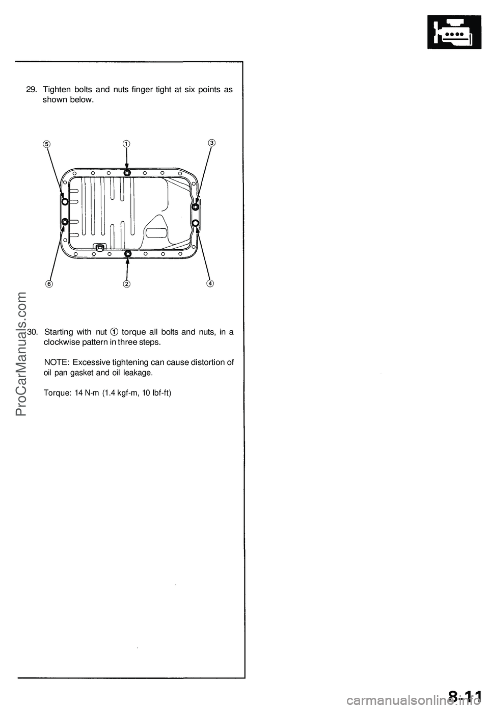
29. Tighten bolts and nuts finger tight at six points as
shown below.
30. Starting with nut torque all bolts and nuts, in a
clockwise pattern in three steps.
NOTE: Excessive tightening can cause distortion of
oil pan gasket and oil leakage.
Torque: 14 N-m (1.4 kgf-m, 10 Ibf-ft)ProCarManuals.com
Page 645 of 1503
Pressure Plate , Clutc h Dis c
Remova l
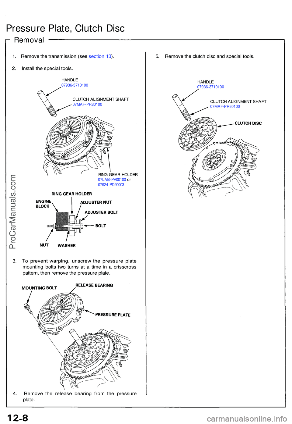
1. Remov e th e transmissio n (se e sectio n 13 ).
2 . Instal l th e specia l tools .
HANDL E07936-371010 0
CLUTCH ALIGNMEN T SHAF T07MAF-PR8010 0
RING GEA R HOLDE R07LAB-PV0010 0 or0792 4-PD2000 3
3. T o preven t warping , unscre w th e pressur e plat e
mountin g bolt s tw o turn s a t a tim e i n a crisscros s
pattern , the n remov e th e pressur e plate .
4 . Remov e th e releas e bearin g fro m th e pressur e
plate.
5. Remov e th e clutc h dis c an d specia l tools .
HANDL E07936-371010 0
CLUTCH ALIGNMEN T SHAF T07MAF-PR8010 0
ProCarManuals.com
Page 790 of 1503
Removal
Valve Bod y
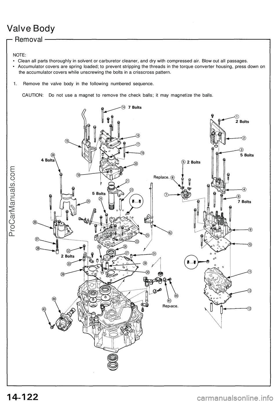
NOTE :
• Clea n al l part s thoroughl y i n solven t o r carbureto r cleaner , an d dr y wit h compresse d air . Blo w ou t al l passages .
• Accumulato r cover s ar e sprin g loaded ; t o preven t strippin g th e thread s i n th e torqu e converte r housing , pres s dow n o n
th e accumulato r cover s whil e unscrewin g th e bolt s i n a crisscros s pattern .
1 . Remov e th e valv e bod y i n th e followin g numbere d sequence .
CAUTION : D o no t us e a magne t t o remov e th e chec k balls ; i t ma y magnetiz e th e balls .
ProCarManuals.com
Page 835 of 1503
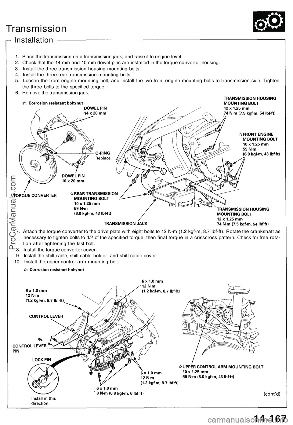
Transmission
Installation
1. Place the transmission on a transmission jack, and raise it to engine level.
2. Check that the 14 mm and 10 mm dowel pins are installed in the torque converter housing.
3. Install the three transmission housing mounting bolts.
4. Install the three rear transmission mounting bolts.
5. Loosen the front engine mounting bolt, and install the two front engine mounting bolts to transmission side. Tighten
the three bolts to the specified torque.
6. Remove the transmission jack.
7. Attach the torque converter to the drive plate with eight bolts to 12 N-m (1.2 kgf-m, 8.7 Ibf-ft). Rotate the crankshaft as
necessary to tighten bolts to 1/2 of the specified torque, then final torque in a crisscross pattern. Check for free rota-
tion after tightening the last bolt.
8. Install the torque converter cover.
9. Install the shift cable, shift cable holder, and shift cable cover.
10. Install the upper control arm mounting bolt.ProCarManuals.com
Page 865 of 1503
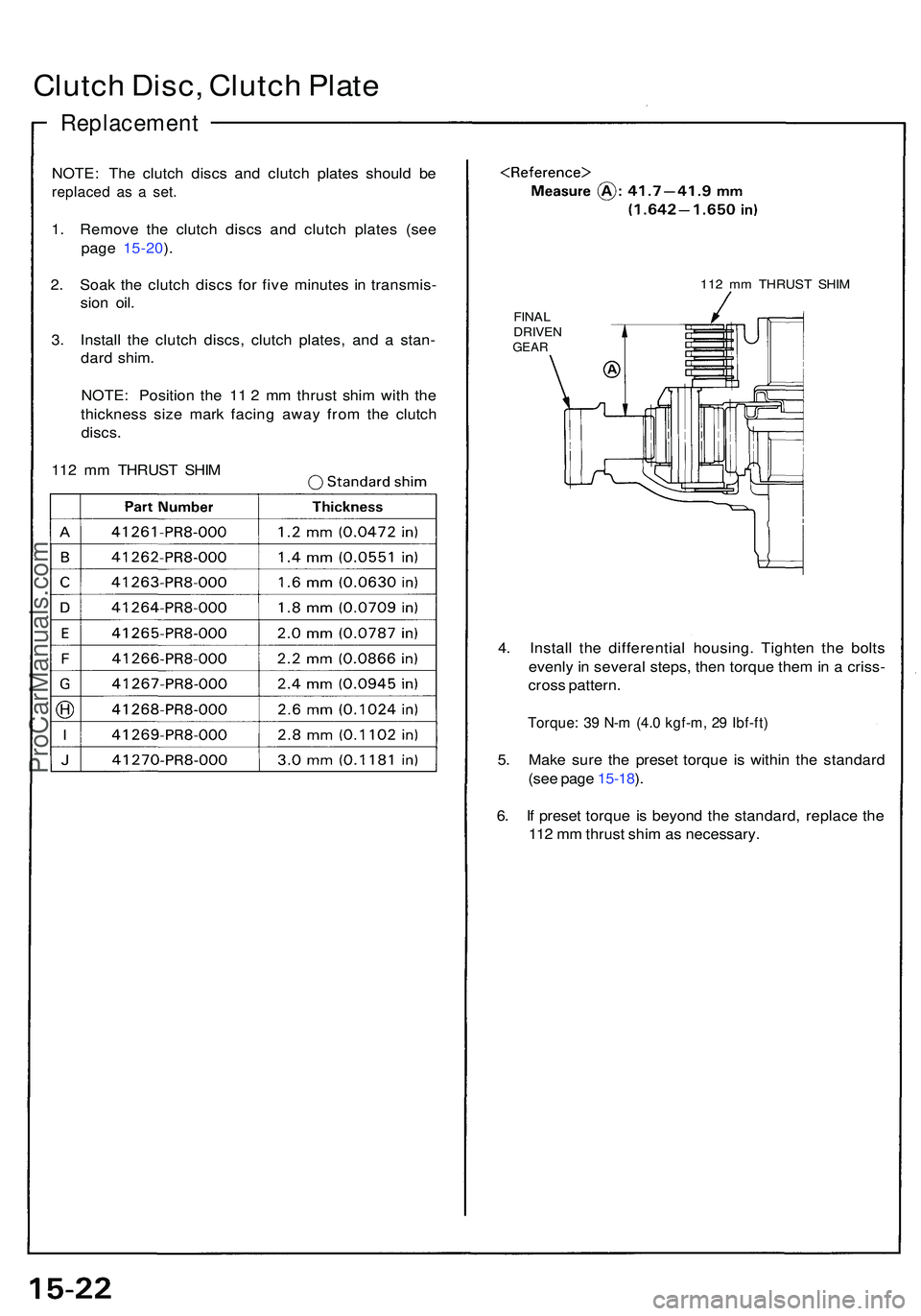
NOTE: Th e clutc h disc s an d clutc h plate s shoul d b e
replace d a s a set .
1. Remov e th e clutc h disc s an d clutc h plate s (se e
pag e 15-20 ).
2 . Soa k th e clutc h disc s fo r fiv e minute s i n transmis -
sio n oil .
3 . Instal l th e clutc h discs , clutc h plates , an d a stan -
dar d shim .
NOTE : Positio n th e 1 1 2 m m thrus t shi m wit h th e
thicknes s siz e mar k facin g awa y fro m th e clutc h
discs.
112 m m THRUS T SHI M
112 m m THRUS T SHI M
FINA L
DRIVE NGEAR
4. Instal l th e differentia l housing . Tighte n th e bolt s
evenl y in severa l steps , the n torqu e the m in a criss -
cros s pattern .
Torque: 3 9 N- m (4. 0 kgf-m , 2 9 Ibf-ft )
5. Mak e sur e th e prese t torqu e i s withi n th e standar d
(se e pag e 15-18 ).
6 . I f prese t torqu e i s beyon d th e standard , replac e th e
11 2 m m thrus t shi m a s necessary .
Clutch Disc , Clutc h Plat e
Replacemen t
ProCarManuals.com