coolant temperature ACURA NSX 1997 Service Repair Manual
[x] Cancel search | Manufacturer: ACURA, Model Year: 1997, Model line: NSX, Model: ACURA NSX 1997Pages: 1503, PDF Size: 57.08 MB
Page 141 of 1503
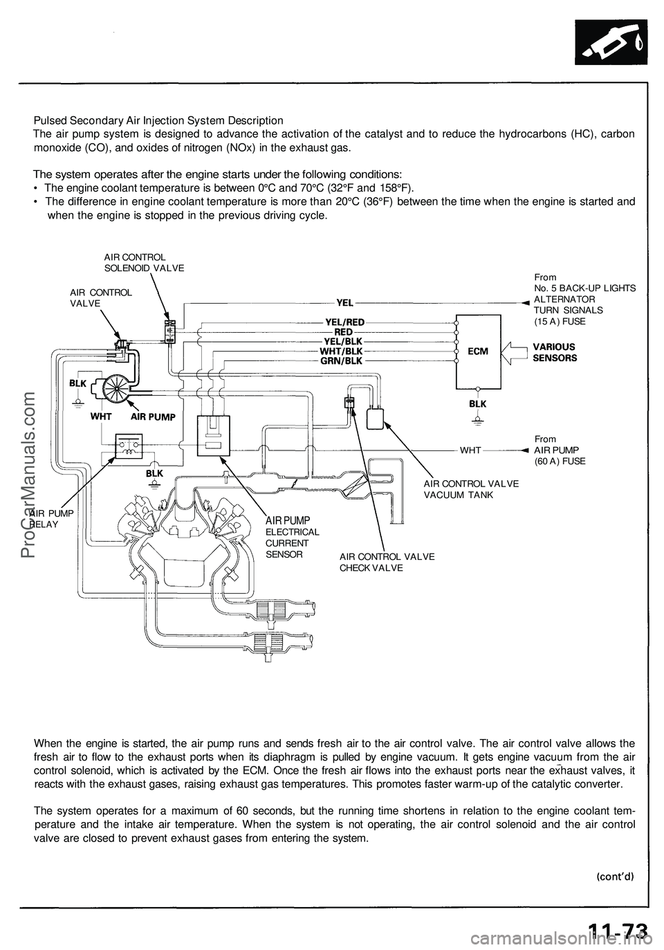
Pulsed Secondary Air Injection System Description
The air pump system is designed to advance the activation of the catalyst and to reduce the hydrocarbons (HC), carbon
monoxide (CO), and oxides of nitrogen (NOx) in the exhaust gas.
The system operates after the engine starts under the following conditions:
• The engine coolant temperature is between 0°C and 70°C (32°F and 158°F).
• The difference in engine coolant temperature is more than 20°C (36°F) between the time when the engine is started and
when the engine is stopped in the previous driving cycle.
AIR CONTROL
SOLENOID VALVE
AIR CONTROL
VALVE
WHT
AIR PUMP
RELAY
From
No. 5 BACK-UP LIGHTS
ALTERNATOR
TURN SIGNALS
(15 A) FUSE
From
AIR PUMP
(60 A) FUSE
AIR CONTROL VALVE
VACUUM TANK
AIR CONTROL VALVE
CHECK VALVE
When the engine is started, the air pump runs and sends fresh air to the air control valve. The air control valve allows the
fresh air to flow to the exhaust ports when its diaphragm is pulled by engine vacuum. It gets engine vacuum from the air
control solenoid, which is activated by the ECM. Once the fresh air flows into the exhaust ports near the exhaust valves, it
reacts with the exhaust gases, raising exhaust gas temperatures. This promotes faster warm-up of the catalytic converter.
The system operates for a maximum of 60 seconds, but the running time shortens in relation to the engine coolant tem-
perature and the intake air temperature. When the system is not operating, the air control solenoid and the air control
valve are closed to prevent exhaust gases from entering the system.
AIR PUMP
ELECTRICAL
CURRENT
SENSORProCarManuals.com
Page 164 of 1503
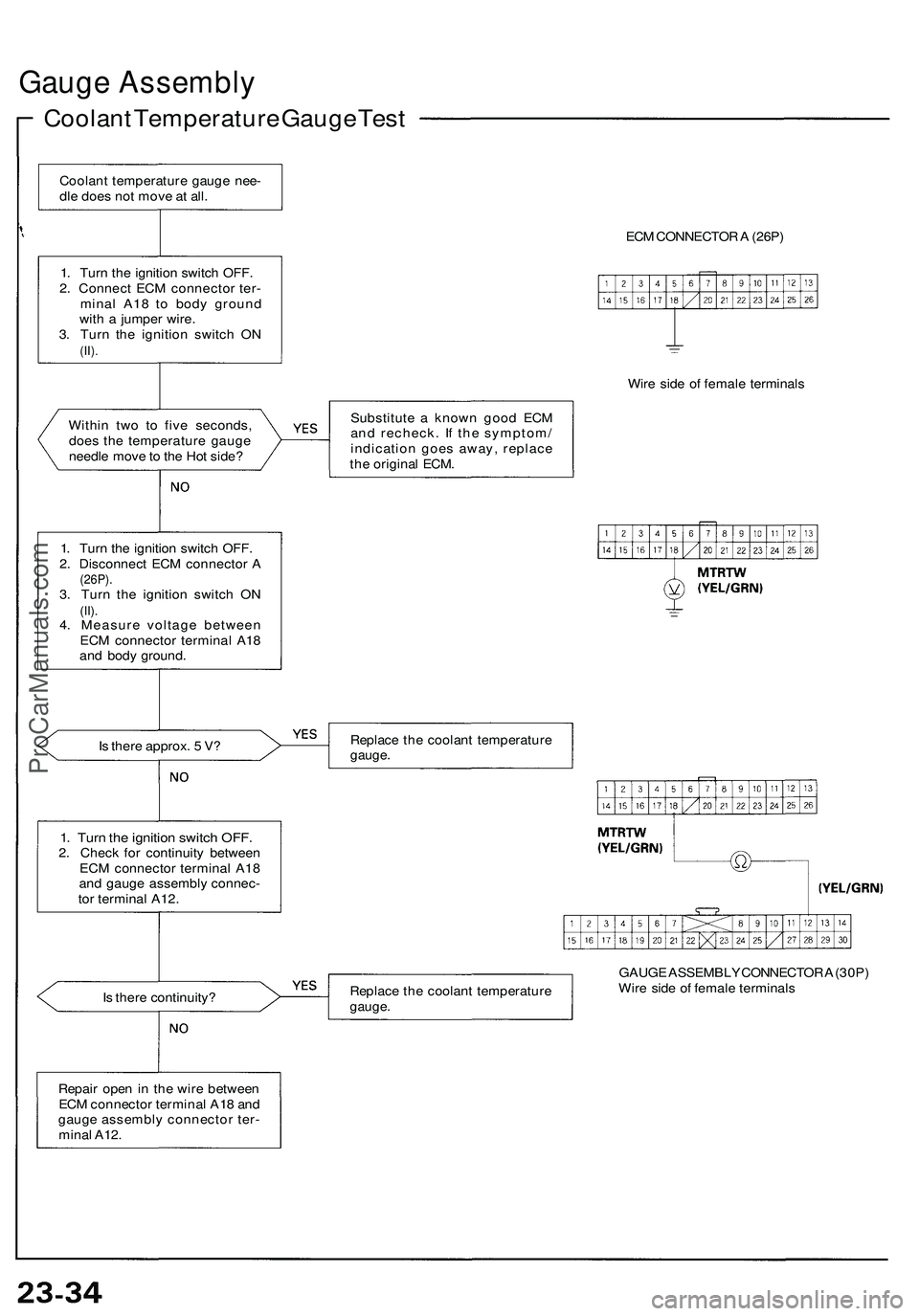
Gauge Assembly
Coolant Temperature Gauge Test
Within two to five seconds,
does the temperature gauge
needle move to the Hot side?
Is there approx. 5 V?
1. Turn the ignition switch OFF.
2. Check for continuity between
ECM connector terminal A18
and gauge assembly connec-
tor terminal A12.
Is there continuity?
ECM CONNECTOR A (26P)
Wire side of female terminals
Substitute a known good ECM
and recheck. If the symptom/
indication goes away, replace
the original ECM.
Replace the coolant temperature
gauge.
Replace the coolant temperature
gauge.
GAUGE ASSEMBLY CONNECTOR A (30P)
Wire side of female terminals
Coolant temperature gauge nee-
dle does not move at all.
1. Turn the ignition switch OFF.
2. Connect ECM connector ter-
minal A18 to body ground
with a jumper wire.
3. Turn the ignition switch ON
(II).
1. Turn the ignition switch OFF.
2. Disconnect ECM connector A
(26P).
3. Turn the ignition switch ON
(II).
4. Measure voltage between
ECM connector terminal A18
and body ground.
Repair open in the wire between
ECM connector terminal A18 and
gauge assembly connector ter-
minal A12.ProCarManuals.com
Page 165 of 1503
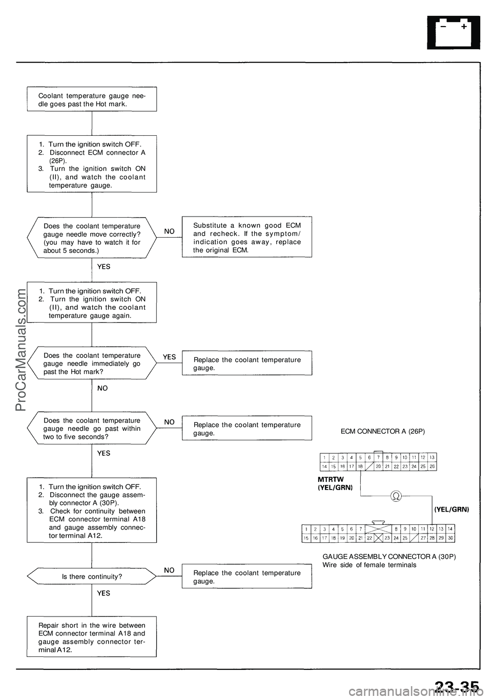
Does the coolant temperature
gauge needle move correctly?
(you may have to watch it for
about 5 seconds.)
1. Turn the ignition switch OFF.
2. Turn the ignition switch ON
(II), and watch the coolant
temperature gauge again.
Does the coolant temperature
gauge needle immediately go
past the Hot mark?
Does the coolant temperature
gauge needle go past within
two to five seconds?
1. Turn the ignition switch OFF.
2. Disconnect the gauge assem-
bly connector A (30P).
3. Check for continuity between
ECM connector terminal A18
and gauge assembly connec-
tor terminal A12.
Is there continuity?
Substitute a known good ECM
and recheck. If the symptom/
indication goes away, replace
the original ECM.
Replace the coolant temperature
gauge.
Replace the coolant temperature
gauge.
ECM CONNECTOR A (26P)
Replace the coolant temperature
gauge.
GAUGE ASSEMBLY CONNECTOR A (30P)
Wire side of female terminals
Repair short in the wire between
ECM connector terminal A18 and
gauge assembly connector ter-
minal A12.
1. Turn the ignition switch OFF.
2. Disconnect ECM connector A
(26P).
3. Turn the ignition switch ON
(II), and watch the coolant
temperature gauge.
Coolant temperature gauge nee-
dle goes past the Hot mark.ProCarManuals.com
Page 193 of 1503
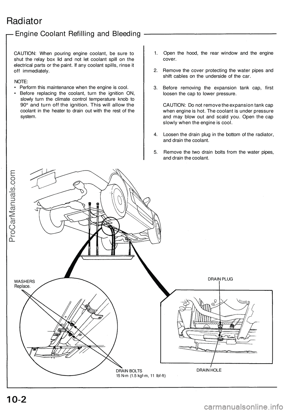
Radiator
Engine Coolant Refilling and Bleeding
CAUTION: When pouring engine coolant, be sure to
shut the relay box lid and not let coolant spill on the
electrical parts or the paint. If any coolant spills, rinse it
off immediately.
NOTE:
• Perform this maintenance when the engine is cool.
• Before replacing the coolant, turn the ignition ON,
slowly turn the climate control temperature knob to
90° and turn off the ignition. This will allow the
coolant in the heater to drain out with the rest of the
system.
1. Open the hood, the rear window and the engine
cover.
2. Remove the cover protecting the water pipes and
shift cables on the underside of the car.
3. Before removing the expansion tank cap, first
loosen the cap to lower pressure.
CAUTION: Do not remove the expansion tank cap
when engine is hot. The coolant is under pressure
and may blow out and scald you. Open the cap
slowly when the engine is cool.
4. Loosen the drain plug in the bottom of the radiator,
and drain the coolant.
5. Remove the two drain bolts from the water pipes,
and drain the coolant.
DRAIN BOLTS
15 N-m (1.5 kgf-m, 11 Ibf-ft)
DRAIN HOLE
DRAIN PLUG
WASHERS
Replace.ProCarManuals.com
Page 438 of 1503
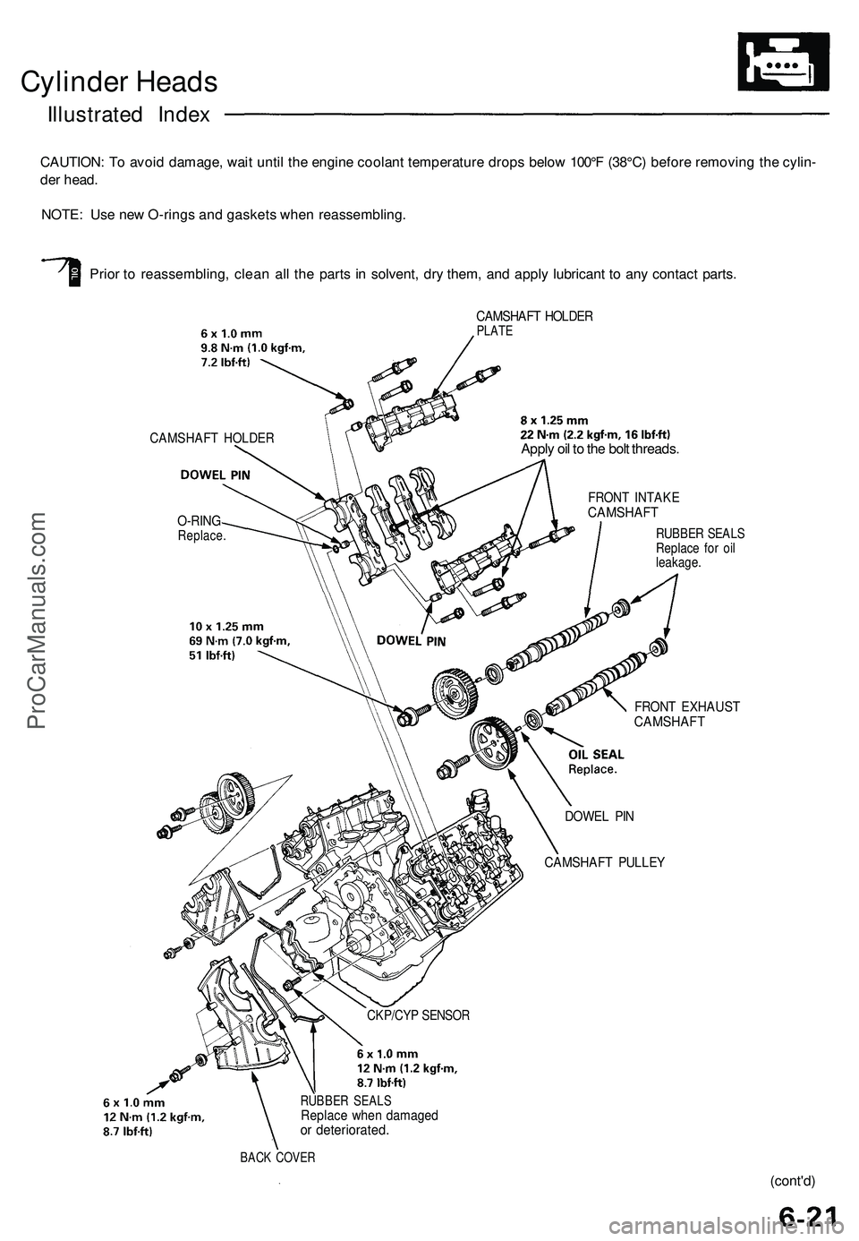
Cylinder Heads
Illustrated Index
CAUTION: To avoid damage, wait until the engine coolant temperature drops below 100°F (38°C) before removing the cylin-
der head.
NOTE: Use new O-rings and gaskets when reassembling.
Prior to reassembling, clean all the parts in solvent, dry them, and apply lubricant to any contact parts.
CAMSHAFT HOLDER
O-RING
Replace.
CAMSHAFT HOLDER
PLATE
CKP/CYP SENSOR
RUBBER SEALS
Replace when damaged
or deteriorated.
BACK COVER
Apply oil to the bolt threads.
FRONT INTAKE
CAMSHAFT
RUBBER SEALS
Replace for oil
leakage.
FRONT EXHAUST
CAMSHAFT
DOWEL PIN
CAMSHAFT PULLEY
(cont'd)ProCarManuals.com
Page 521 of 1503
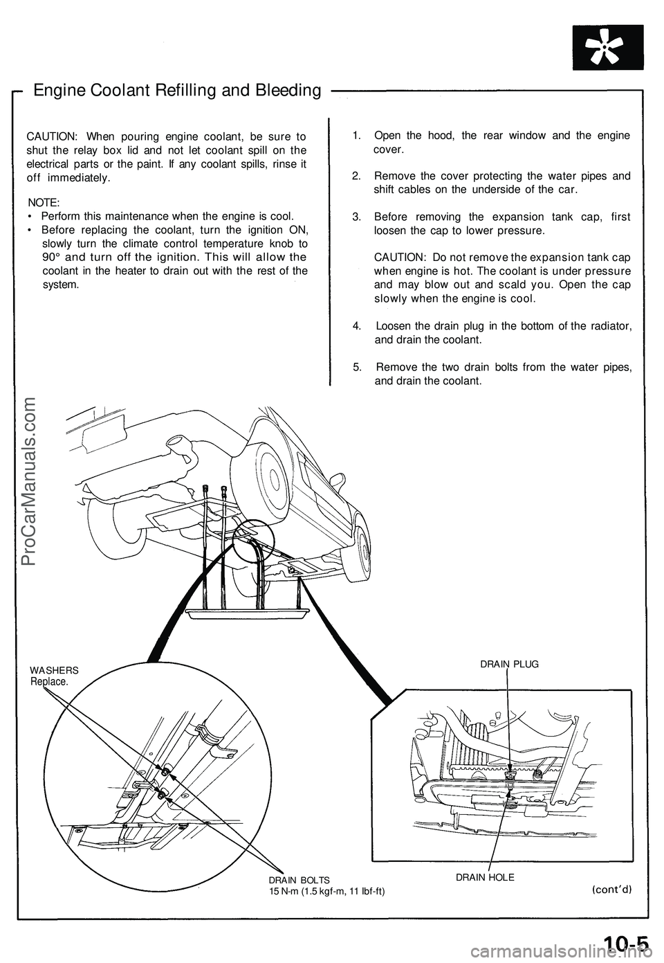
Engine Coolant Refilling and Bleeding
CAUTION: When pouring engine coolant, be sure to
shut the relay box lid and not let coolant spill on the
electrical parts or the paint. If any coolant spills, rinse it
off immediately.
NOTE:
• Perform this maintenance when the engine is cool.
• Before replacing the coolant, turn the ignition ON,
slowly turn the climate control temperature knob to
90° and turn off the ignition. This will allow the
coolant in the heater to drain out with the rest of the
system.
1. Open the hood, the rear window and the engine
cover.
2. Remove the cover protecting the water pipes and
shift cables on the underside of the car.
3. Before removing the expansion tank cap, first
loosen the cap to lower pressure.
CAUTION: Do not remove the expansion tank cap
when engine is hot. The coolant is under pressure
and may blow out and scald you. Open the cap
slowly when the engine is cool.
4. Loosen the drain plug in the bottom of the radiator,
and drain the coolant.
5. Remove the two drain bolts from the water pipes,
and drain the coolant.
WASHERS
Replace.
DRAIN BOLTS
15 N-m (1.5 kgf-m, 11 Ibf-ft)
DRAIN HOLE
DRAIN PLUGProCarManuals.com
Page 570 of 1503
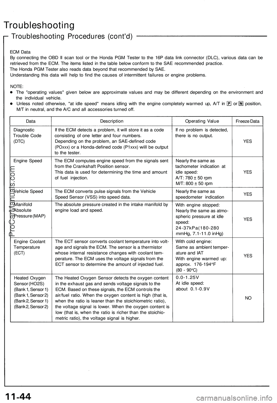
Troubleshooting
Troubleshooting Procedures (cont'd)
ECM Data
By connecting the OBD II scan tool or the Honda PGM Tester to the 16P data link connector (DLC), various data can be
retrieved from the ECM. The items listed in the table below conform to the SAE recommended practice.
The Honda PGM Tester also reads data beyond that recommended by SAE.
Understanding this data will help to find the causes of intermittent failures or engine problems.
NOTE:
The "operating values" given below are approximate values and may be different depending on the environment and
the individual vehicle.
Unless noted otherwise, "at idle speed" means idling with the engine completely warmed up, A/T in or position,
M/T in neutral, and the A/C and all accessories turned off.
Data
Description
Operating Value
Freeze Data
Diagnostic
Trouble Code
(DTC)
If the ECM detects a problem, it will store it as a code
consisting of one letter and four numbers.
Depending on the problem, an SAE-defined code
(POxxx)
or a
Honda-defined code
(P1xxx)
will
be
output
to the tester.
If no problem is detected,
there is no output.
YES
Engine Speed
The ECM computes engine speed from the signals sent
from the Crankshaft Position sensor.
This data is used for determining the time and amount
of fuel injection.
Nearly the same as
tachometer indication at
idle speed:
A/T:
780 ± 50 rpm
M/T:
800 ± 50 rpm
YES
Vehicle Speed
The ECM converts pulse signals from the Vehicle
Speed Sensor (VSS) into speed data.
Nearly the same as
speedometer indication
YES
Manifold
Absolute
Pressure (MAP)
The absolute pressure created in the intake manifold by
engine load and speed.
With engine stopped:
Nearly the same as atmo-
spheric pressure at idle
speed:
24-37kPa(180-280
mmHg, 7.1-11.0 inHg)
YES
Engine Coolant
Temperature
(ECT)
The ECT sensor converts coolant temperature into volt-
age and signals the ECM. The sensor is a thermistor
whose internal resistance changes with coolant tem-
perature. The ECM uses the voltage signals from the
ECT sensor to determine the amount of injected fuel.
With cold engine:
Same as ambient temper-
ature and IAT
With engine warmed up:
approx. 176-194°F
(80 - 90°C)
YES
Heated Oxygen
Sensor (HO2S)
(Bank 1, Sensor 1)
(Bank 1, Sensor 2)
(Bank 2, Sensor 1)
(Bank 2, Sensor 2)
The Heated Oxygen Sensor detects the oxygen content
in the exhaust gas and sends voltage signals to the
ECM. Based on these signals, the ECM controls the
air/fuel ratio. When the oxygen content is high (that is,
when the ratio is leaner than the stoichiometric ratio),
the voltage signal is lower. When the oxygen content is
low (that is, when the ratio is richer than the stoichio-
metric ratio), the voltage signal is higher.
0.0-1.25V
At idle speed:
about 0.1-0.9V
NOProCarManuals.com
Page 586 of 1503
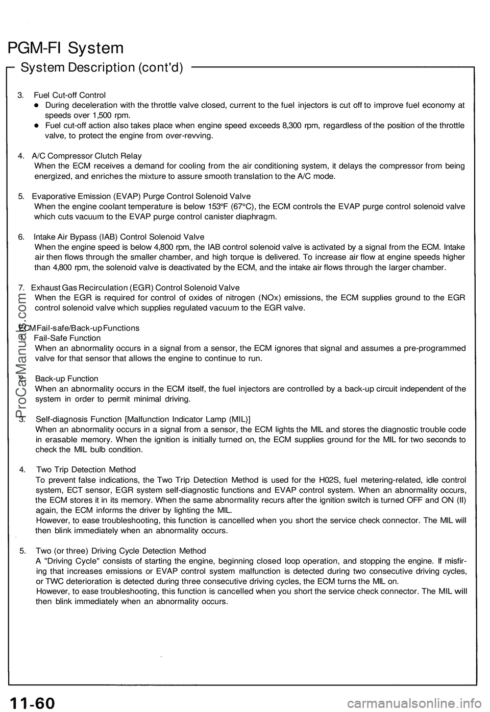
PGM-FI System
System Description (cont'd)
3. Fuel Cut-off Control
During deceleration with the throttle valve closed, current to the fuel injectors is cut off to improve fuel economy at
speeds over 1,500 rpm.
Fuel cut-off action also takes place when engine speed exceeds 8,300 rpm, regardless of the position of the throttle
valve, to protect the engine from over-revving.
4. A/C Compressor Clutch Relay
When the ECM receives a demand for cooling from the air conditioning system, it delays the compressor from being
energized, and enriches the mixture to assure smooth translation to the A/C mode.
5. Evaporative Emission (EVAP) Purge Control Solenoid Valve
When the engine coolant temperature is below 153°F (67°C), the ECM controls the EVAP purge control solenoid valve
which cuts vacuum to the EVAP purge control canister diaphragm.
6. Intake Air Bypass (IAB) Control Solenoid Valve
When the engine speed is below 4,800 rpm, the IAB control solenoid valve is activated by a signal from the ECM. Intake
air then flows through the smaller chamber, and high torque is delivered. To increase air flow at engine speeds higher
than 4,800 rpm, the solenoid valve is deactivated by the ECM, and the intake air flows through the larger chamber.
7. Exhaust Gas Recirculation (EGR) Control Solenoid Valve
When the EGR is required for control of oxides of nitrogen (NOx) emissions, the ECM supplies ground to the EGR
control solenoid valve which supplies regulated vacuum to the EGR valve.
ECM Fail-safe/Back-up Functions
1. Fail-Safe Function
When an abnormality occurs in a signal from a sensor, the ECM ignores that signal and assumes a pre-programmed
valve for that sensor that allows the engine to continue to run.
2. Back-up Function
When an abnormality occurs in the ECM itself, the fuel injectors are controlled by a back-up circuit independent of the
system in order to permit minimal driving.
3. Self-diagnosis Function [Malfunction Indicator Lamp (MIL)]
When an abnormality occurs in a signal from a sensor, the ECM lights the MIL and stores the diagnostic trouble code
in erasable memory. When the ignition is initially turned on, the ECM supplies ground for the MIL for two seconds to
check the MIL bulb condition.
4. Two Trip Detection Method
To prevent false indications, the Two Trip Detection Method is used for the H02S, fuel metering-related, idle control
system, ECT sensor, EGR system self-diagnostic functions and EVAP control system. When an abnormality occurs,
the ECM stores it in its memory. When the same abnormality recurs after the ignition switch is turned OFF and ON (II)
again, the ECM informs the driver by lighting the MIL.
However, to ease troubleshooting, this function is cancelled when you short the service check connector. The MIL will
then blink immediately when an abnormality occurs.
5. Two (or three) Driving Cycle Detection Method
A "Driving Cycle" consists of starting the engine, beginning closed loop operation, and stopping the engine. If misfir-
ing that increases emissions or EVAP control system malfunction is detected during two consecutive driving cycles,
or TWC deterioration is detected during three consecutive driving cycles, the ECM turns the MIL on.
However,
to
ease
troubleshooting,
this
function
is
cancelled when
you
short
the
service check connector.
The MIL
will
then blink immediately when an abnormality occurs.ProCarManuals.com
Page 756 of 1503
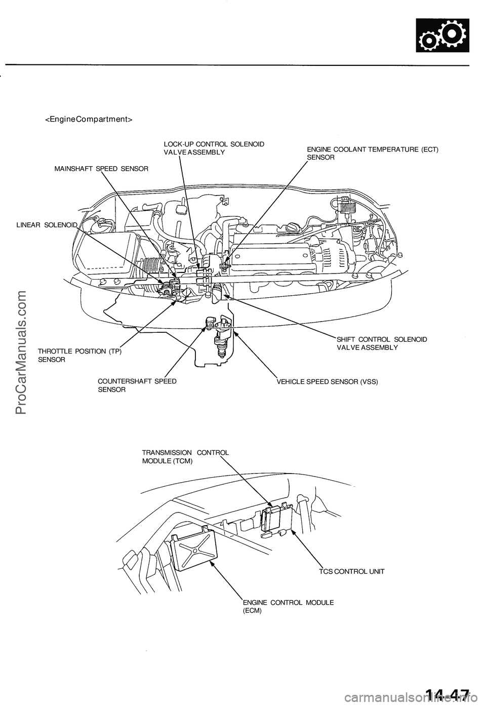
LOCK-UP CONTROL SOLENOID
VALVE ASSEMBLY
MAINSHAFT SPEED SENSOR
LINEAR SOLENOID
ENGINE COOLANT TEMPERATURE (ECT)
SENSOR
THROTTLE POSITION (TP)
SENSOR
COUNTERSHAFT SPEED
SENSOR
SHIFT CONTROL SOLENOID
VALVE ASSEMBLY
VEHICLE SPEED SENSOR (VSS)
TRANSMISSION CONTROL
MODULE (TCM)
TCS CONTROL UNIT
ENGINE CONTROL MODULE
(ECM)ProCarManuals.com
Page 1184 of 1503
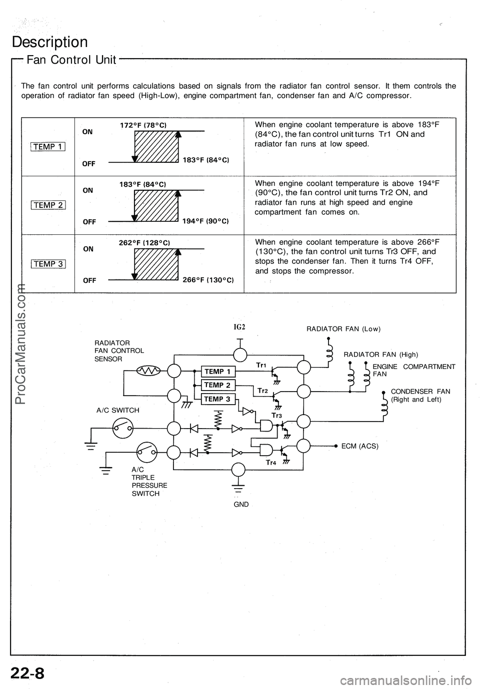
Description
Fan Control Unit
The fan control unit performs calculations based on signals from the radiator fan control sensor. It them controls the
operation of radiator fan speed (High-Low), engine compartment fan, condenser fan and A/C compressor.
When engine coolant temperature is above 183°F
(84°C), the fan control unit turns Tr1 ON and
radiator fan runs at low speed.
When engine coolant temperature is above 194°F
(90°C), the fan control unit turns Tr2 ON, and
radiator fan runs at high speed and engine
compartment fan comes on.
When engine coolant temperature is above 266°F
(130°C), the fan control unit turns Tr3 OFF, and
stops the condenser fan. Then it turns Tr4 OFF,
and stops the compressor.
IG2
RADIATOR FAN (Low)
RADIATOR
FAN CONTROL
SENSOR
RADIATOR FAN (High)
ENGINE COMPARTMENT
FAN
CONDENSER FAN
(Right and Left)
ECM
(ACS)
A/C
TRIPLE
PRESSURE
SWITCH
GND
A/C SWITCHProCarManuals.com