mirror ACURA NSX 1997 Service Repair Manual
[x] Cancel search | Manufacturer: ACURA, Model Year: 1997, Model line: NSX, Model: ACURA NSX 1997Pages: 1503, PDF Size: 57.08 MB
Page 1064 of 1503
Doors
Disassembly (cont'd)
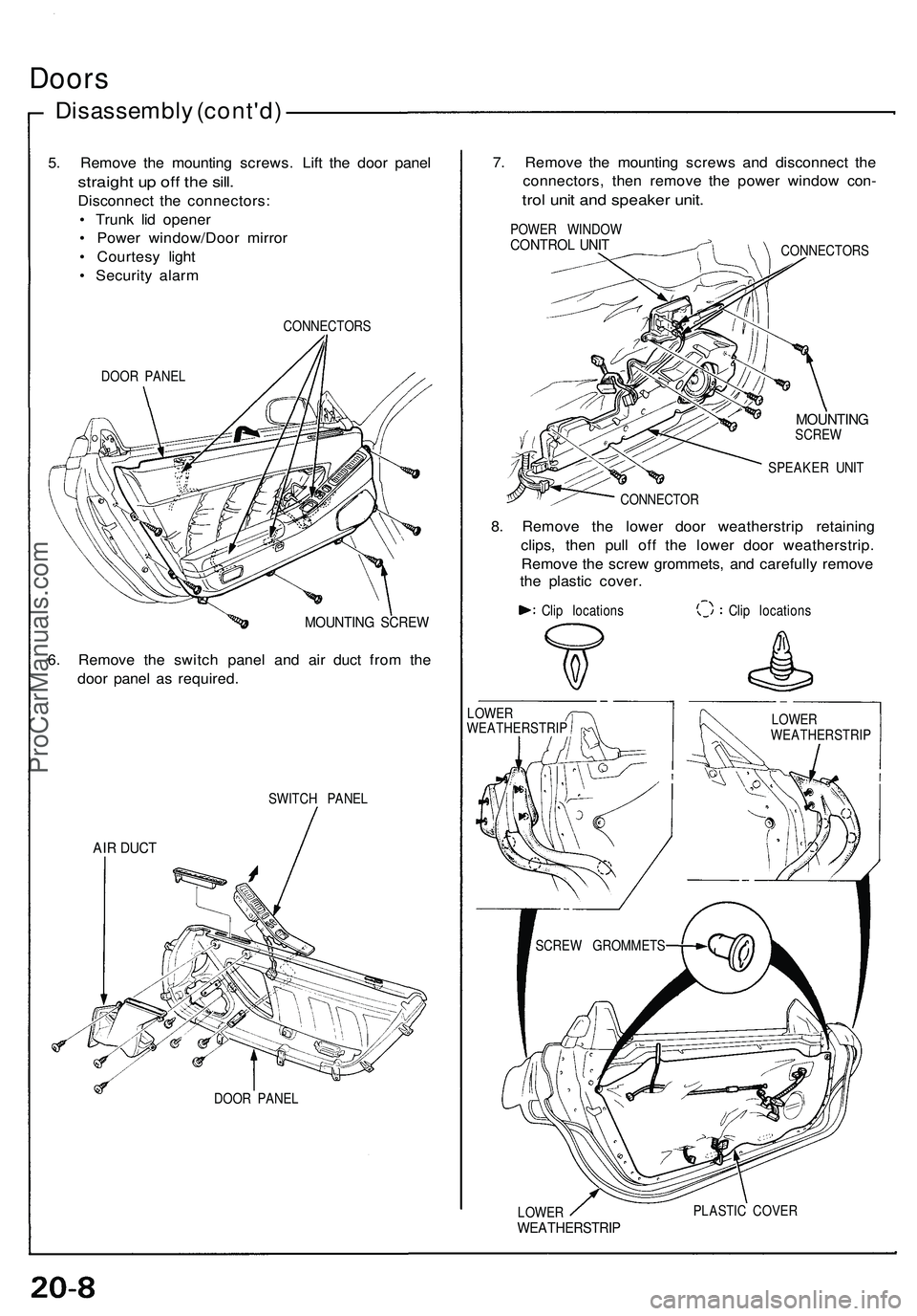
5. Remove the mounting screws. Lift the door panel
straight up off the sill.
Disconnect the connectors:
• Trunk lid opener
• Power window/Door mirror
• Courtesy light
• Security alarm
DOOR PANEL
CONNECTORS
MOUNTING SCREW
6. Remove the switch panel and air duct from the
door panel as required.
SWITCH PANEL
AIR DUCT
DOOR PANEL
7. Remove the mounting screws and disconnect the
connectors, then remove the power window con-
trol unit and speaker unit.
POWER WINDOW
CONTROL UNIT
CONNECTORS
MOUNTING
SCREW
SPEAKER UNIT
CONNECTOR
8. Remove the lower door weatherstrip retaining
clips, then pull off the lower door weatherstrip.
Remove the screw grommets, and carefully remove
the plastic cover.
Clip locations
Clip locations
LOWER
WEATHERSTRIP
PLASTIC COVER
LOWER
WEATHERSTRIP
LOWER
WEATHERSTRIP
SCREW GROMMETSProCarManuals.com
Page 1076 of 1503
Mirror
Remova l
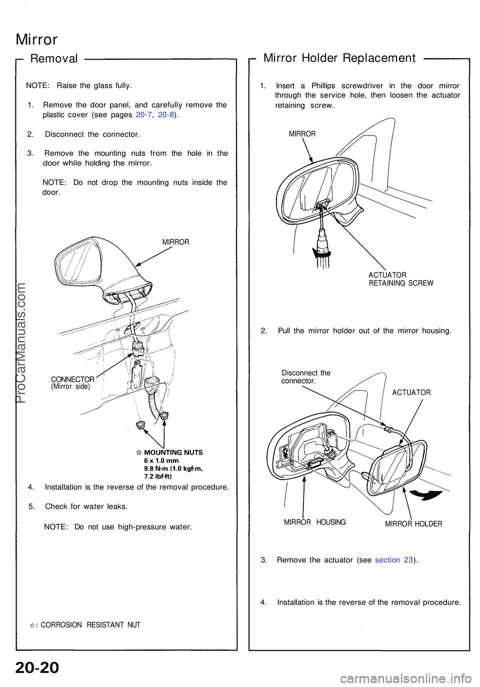
NOTE: Rais e th e glas s fully .
1 . Remov e th e doo r panel , an d carefull y remov e th e
plasti c cove r (se e page s 20-7 , 20-8 ).
2 . Disconnec t th e connector .
3 . Remov e th e mountin g nut s fro m th e hol e i n th e
doo r whil e holdin g th e mirror .
NOTE: D o no t dro p th e mountin g nut s insid e th e
door .
MIRRO R
CONNECTO R(Mirror side )
4. Installatio n i s th e revers e o f th e remova l procedure .
5 . Chec k fo r wate r leaks .
NOTE : D o no t us e high-pressur e water .
CORROSIO N RESISTAN T NU T
Mirro r Holde r Replacemen t
1. Inser t a Phillip s screwdrive r i n th e doo r mirro r
throug h th e servic e hole , the n loose n th e actuato r
retainin g screw .
MIRROR
ACTUATOR
RETAININ G SCRE W
2. Pul l th e mirro r holde r ou t of the mirro r housing .
Disconnec t th econnector .
ACTUATO R
MIRRO R HOUSIN G
MIRROR HOLDE R
3. Remov e th e actuato r (se e sectio n 23 ).
4 . Installatio n i s th e revers e of the remova l procedure .
ProCarManuals.com
Page 1105 of 1503
Seat Belts
Child Seat Anchor Plate
An attachment point is provided for a child restraint
system which uses a top tether. The tether bracket and
bolt are available at your Acura dealer. The tether at-
tachment point is located on the panel behind the
passenger's seat-back.
1. Adjust the passenger seat fully forward to make
room behind the seat-back.
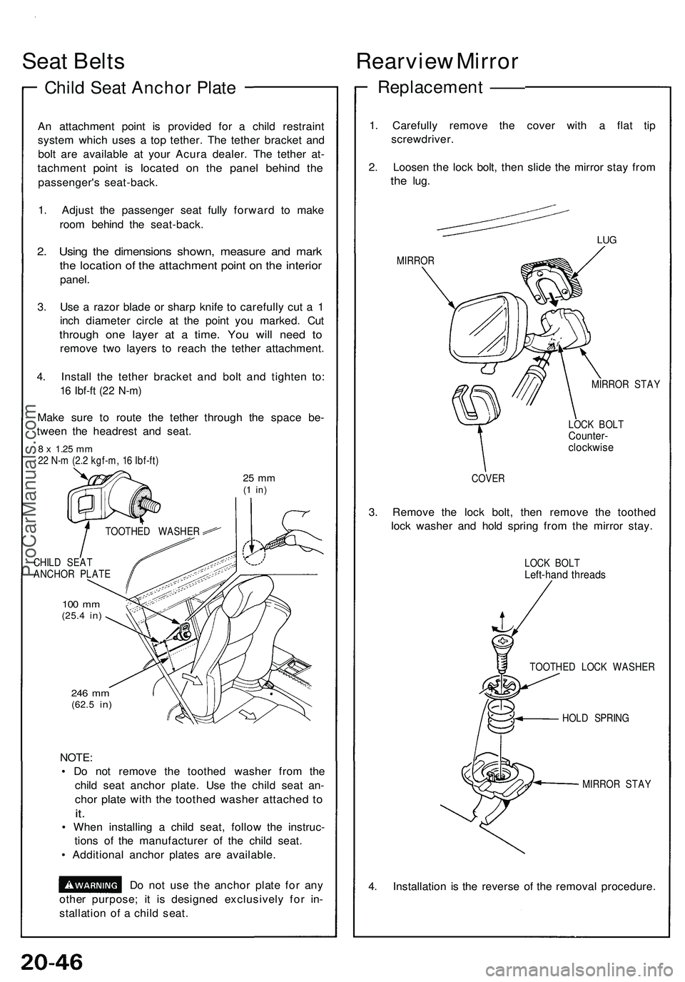
2. Using the dimensions shown, measure and mark
the location of the attachment point on the interior
panel.
3. Use a razor blade or sharp knife to carefully cut a 1
inch diameter circle at the point you marked. Cut
through one layer at a time. You will need to
remove two layers to reach the tether attachment.
4. Install the tether bracket and bolt and tighten to:
16 Ibf-ft (22 N-m)
Make sure to route the tether through the space be-
tween the headrest and seat.
8 x
1.25
mm
22 N-m (2.2 kgf-m, 16 Ibf-ft)
25 mm
(1 in)
CHILD SEAT
ANCHOR PLATE
100 mm
(25.4
in)
246 mm
(62.5
in)
NOTE:
• Do not remove the toothed washer from the
child seat anchor plate. Use the child seat an-
chor plate with the toothed washer attached to
it.
• When installing a child seat, follow the instruc-
tions of the manufacturer of the child seat.
• Additional anchor plates are available.
Do not use the anchor plate for any
other purpose; it is designed exclusively for in-
stallation of a child seat.
Rearview Mirror
Replacement ——
1. Carefully remove the cover with a flat tip
screwdriver.
2. Loosen the lock bolt, then slide the mirror stay from
the
lug.
MIRROR
LUG
MIRROR STAY
LOCK BOLT
Counter-
clockwise
COVER
3. Remove the lock bolt, then remove the toothed
lock washer and hold spring from the mirror stay.
LOCK BOLT
Left-hand threads
TOOTHED LOCK WASHER
HOLD SPRING
MIRROR STAY
4. Installation is the reverse of the removal procedure.
TOOTHED WASHERProCarManuals.com
Page 1401 of 1503
Power Mirror s
- Componen t Locatio n Inde x
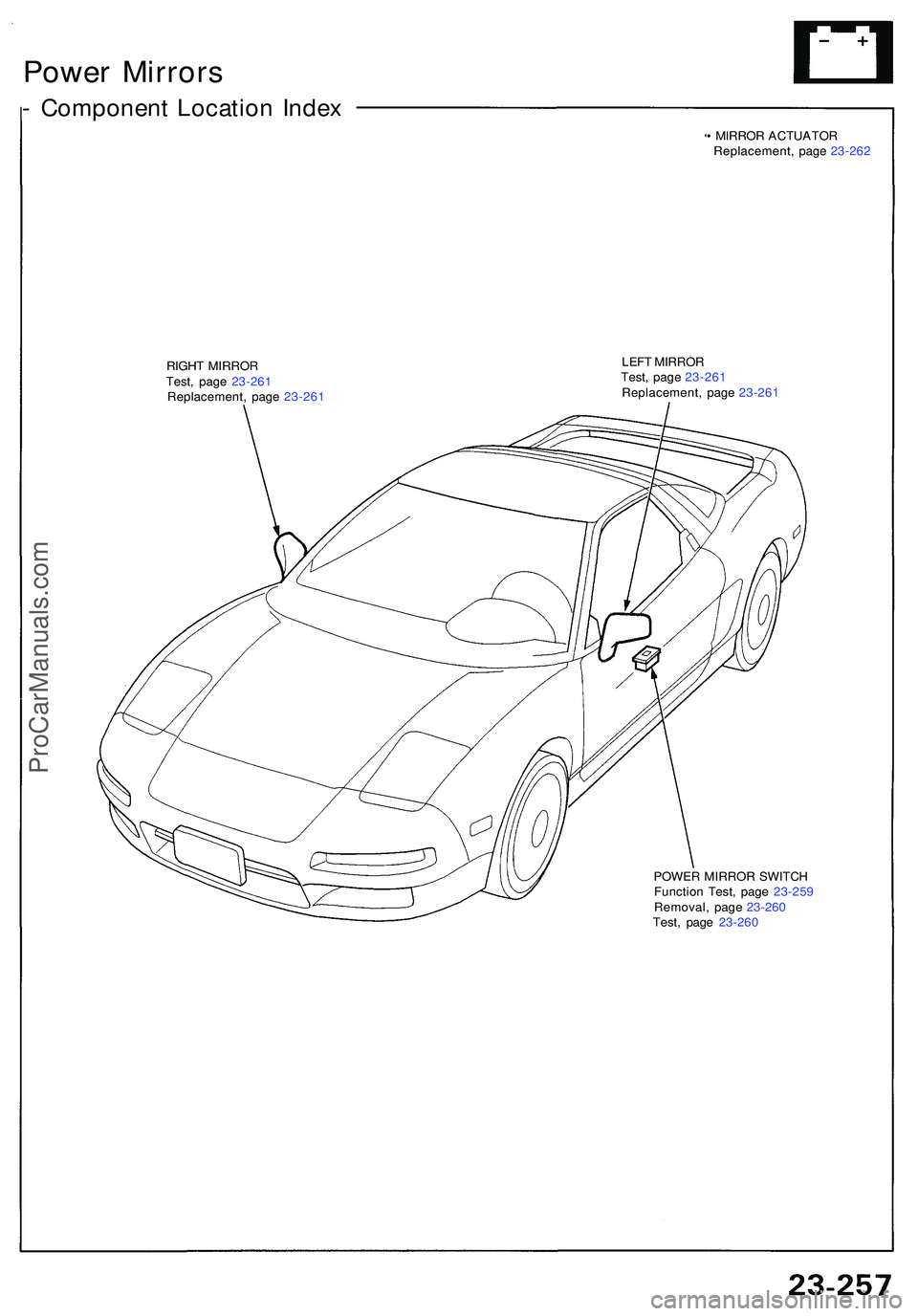
• MIRRO R ACTUATO R
Replacement , pag e 23-26 2
RIGH T MIRRO R
Test , pag e 23-26 1
Replacement , pag e 23-26 1 LEF
T MIRRO R
Test , pag e 23-26 1
Replacement , pag e 23-26 1
POWE R MIRRO R SWITC H
Functio n Test , pag e 23-25 9
Removal , pag e 23-26 0
Test , pag e 23-26 0
ProCarManuals.com
Page 1402 of 1503
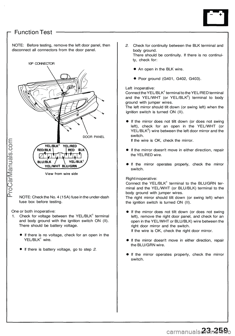
Function Test
NOTE: Before testing, remove the left door panel, then
disconnect all connectors from the door panel.
10P CONNECTOR
DOOR PANEL
NOTE: Check the No. 4 (15A) fuse in the under-dash
fuse box before testing.
One or both inoperative:
1. Check for voltage between the YEL/BLK1 terminal
and body ground with the ignition switch ON (II).
There should be battery voltage.
If there is no voltage, check for an open in the
YEL/BLK1 wire.
If there is battery voltage, go to step 2.
2. Check for continuity between the BLK terminal and
body ground.
There should be continuity. If there is no continui-
ty, check for:
An open in the BLK wire.
Poor ground (G401, G402, G403).
Left inoperative:
Connect the YEL/BLK1 terminal to the YEL/RED terminal
and the YEL/WHT (or YEL/BLK2) terminal to body
ground with jumper wires.
The left mirror should tilt down (or swing left) when the
ignition switch is turned ON (II).
If the
mirror does
not
tilt
down
(or
does
not
swing
left), check for an open in the YEL/WHT (or
YEL/BLK2) wire between the left door mirror and the
switch.
If the wire is OK, check the mirror.
If the mirror doesn't move in either direction, repair
the YEL/RED wire.
If the mirror operates properly, check the mirror
switch.
Right inoperative:
Connect the YEL/BLK1 terminal to the BLU/GRN ter-
minal and the YEL/WHT (or BLU/BLK) terminal to the
body ground with jumper wires.
The
right
mirror should
tilt
down
(or
swing left) when
the ignition switch is turned ON (II).
If the
mirror does
not
tilt
down
(or
does
not
swing
left), remove the right door panel, and check for an
open in the YEL/WHT or BLU/BLK) wire between the
right door mirror and the switch.
If the wire is OK, check the right door mirror.
If the mirror doesn't move in either direction, repair
the BLU/GRN wire.
If the mirror operates properly, check the mirror
switch.ProCarManuals.com
Page 1403 of 1503
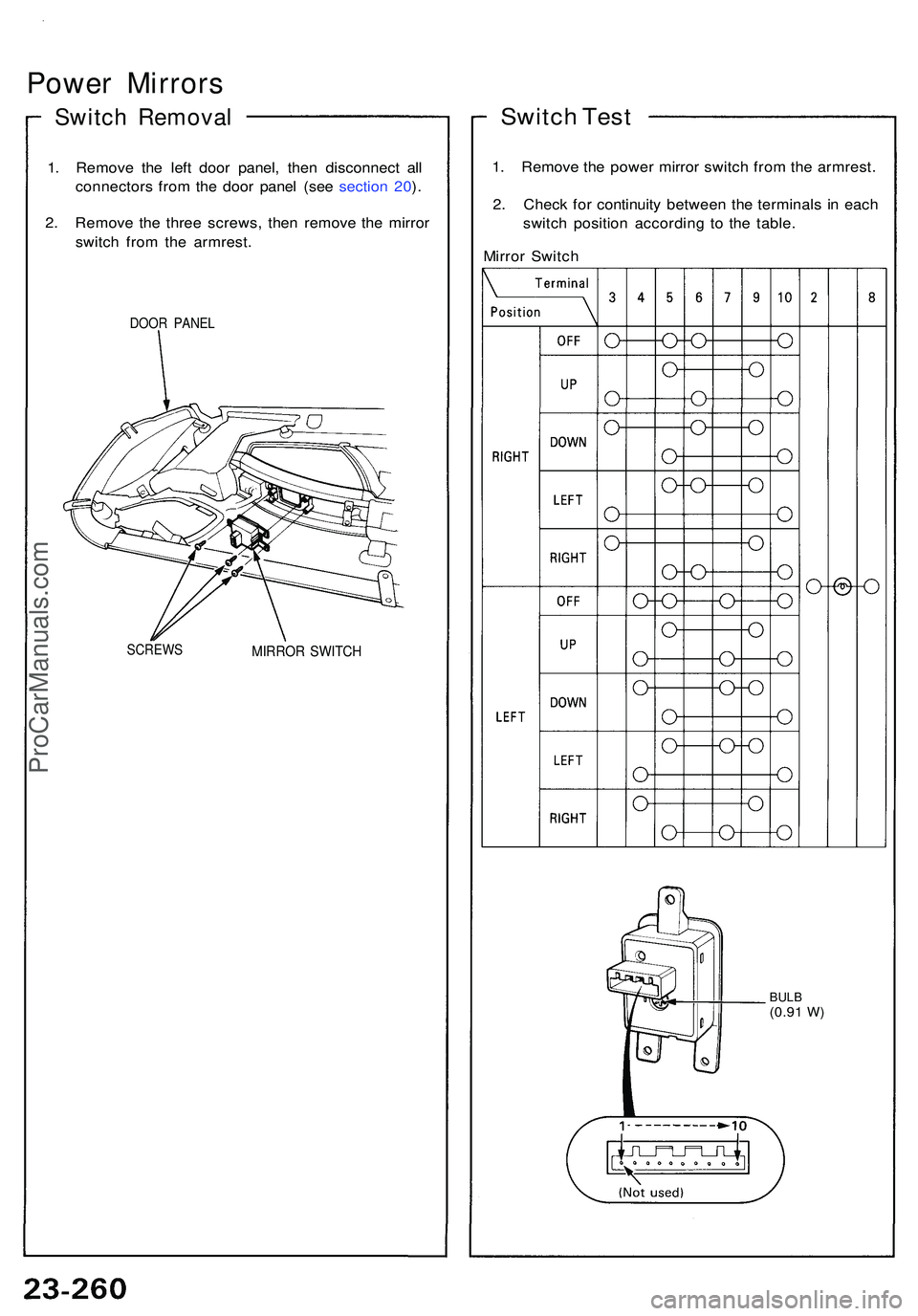
Power Mirror s
Switch Remova l
1. Remov e th e lef t doo r panel , the n disconnec t al l
connector s fro m th e doo r pane l (se e sectio n 20 ).
2 . Remov e th e thre e screws , the n remov e th e mirro r
switc h fro m th e armrest .
DOOR PANE L
SCREW S
MIRROR SWITC H
Switch Tes t
1. Remov e th e powe r mirro r switc h fro m th e armrest .
2 . Chec k fo r continuit y betwee n th e terminal s i n eac h
switc h positio n accordin g t o th e table .
Mirro r Switc h
BULB(0.91 W)
ProCarManuals.com
Page 1404 of 1503
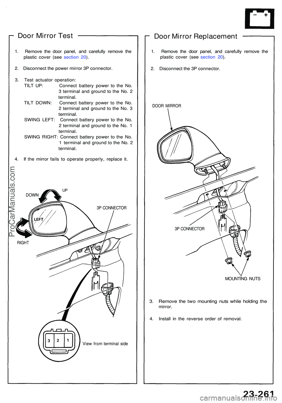
Door Mirro r Tes t
1. Remov e th e doo r panel , an d carefull y remov e th e
plasti c cove r (se e sectio n 20 ).
2 . Disconnec t th e powe r mirro r 3 P connector .
3 . Tes t actuato r operation :
TIL T UP : Connec t batter y powe r t o th e No .
3 termina l an d groun d t o th e No . 2
terminal .
TIL T DOWN : Connec t batter y powe r t o th e No .
2 termina l an d ground to th e No . 3
terminal .
SWING LEFT : Connec t batter y powe r t o th e No .
2 termina l an d ground to th e No . 1
terminal .
SWIN G RIGHT : Connec t batter y powe r t o th e No .
1 termina l an d groun d t o th e No . 2
terminal .
4 . I f th e mirro r fail s t o operat e properly , replac e it .
DOW N
3P CONNECTO R
View fro m termina l sid e
Doo r Mirro r Replacemen t
1. Remov e th e doo r panel , an d carefull y remov e th e
plasti c cove r (se e sectio n 20 ).
2 . Disconnec t th e 3 P connector .
DOOR MIRRO R
MOUNTIN G NUT S
3. Remov e th e tw o mountin g nut s whil e holdin g th e
mirror .
4 . Instal l i n th e revers e orde r o f removal .
RIGHT
UP
3P CONNECTO R
ProCarManuals.com
Page 1405 of 1503
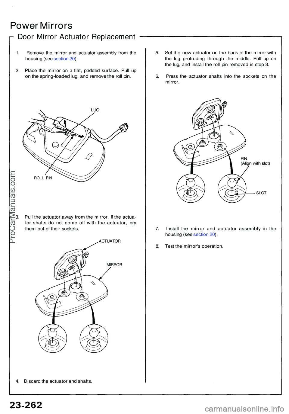
Power Mirror s
Door Mirro r Actuato r Replacemen t
1. Remov e th e mirro r an d actuato r assembl y fro m th e
housin g (se e sectio n 20 ).
2 . Plac e th e mirro r o n a flat , padde d surface . Pul l u p
on th e spring-loade d lug , an d remov e th e rol l pin .
5. Se t th e ne w actuato r o n th e bac k o f th e mirro r wit h
the lu g protrudin g throug h th e middle . Pul l u p o n
th e lug , an d instal l th e rol l pi n remove d in ste p 3 .
6 . Pres s th e actuato r shaft s int o th e socket s o n th e
mirror .
LUG
ROL L PI N
3. Pul l th e actuato r awa y fro m th e mirror . I f th e actua -
to r shaft s d o no t com e of f wit h th e actuator , pr y
the m ou t o f thei r sockets .
ACTUATO R
MIRROR
4. Discar d th e actuato r an d shafts .
PIN(Alig n wit h slot )
SLO T
7. Instal l th e mirro r an d actuato r assembl y i n th e
housin g (se e sectio n 20 ).
8 . Tes t th e mirror' s operation .
ProCarManuals.com