cruise control ACURA NSX 1997 Service Repair Manual
[x] Cancel search | Manufacturer: ACURA, Model Year: 1997, Model line: NSX, Model: ACURA NSX 1997Pages: 1503, PDF Size: 57.08 MB
Page 576 of 1503
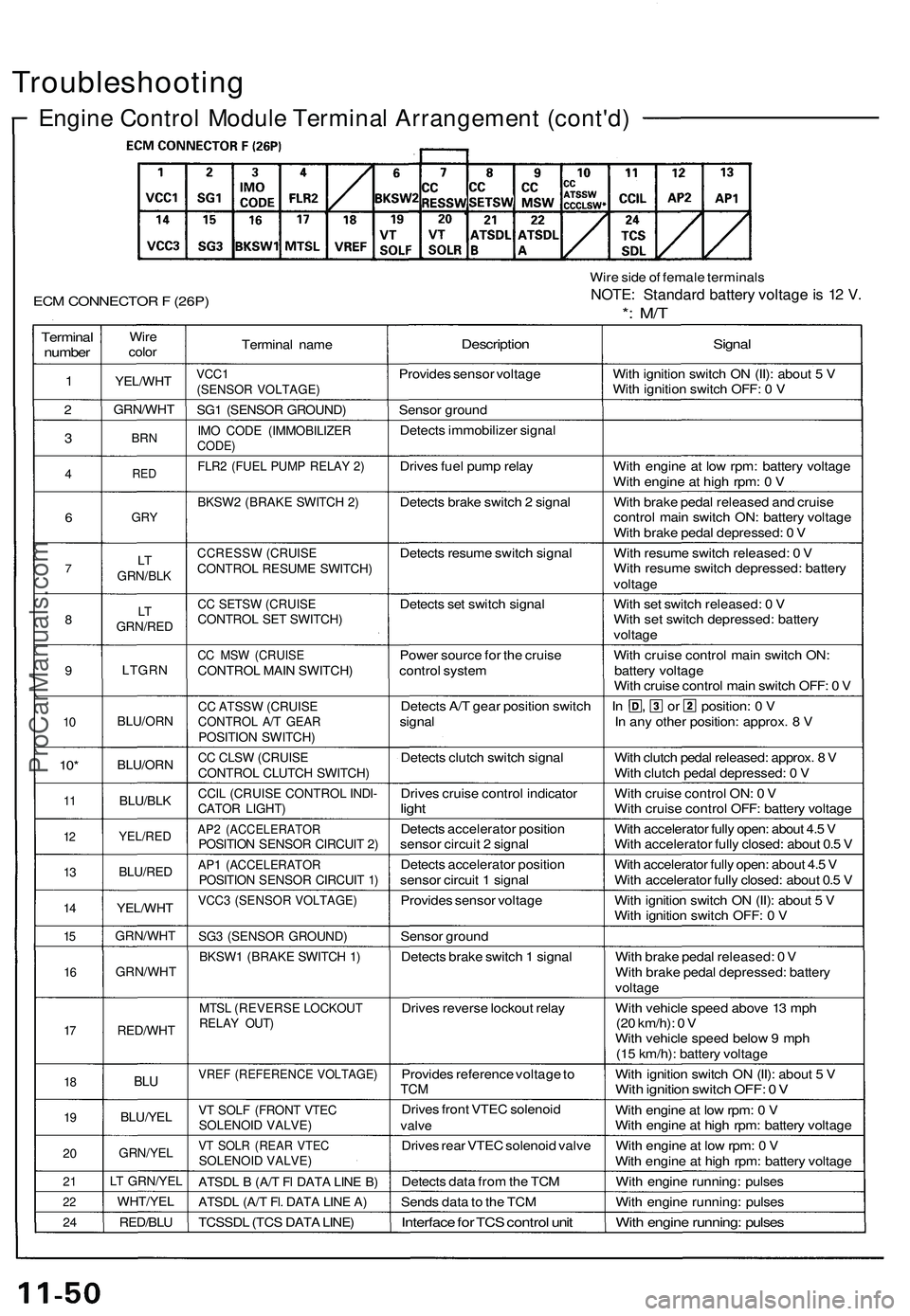
Troubleshooting
Engine Control Module Terminal Arrangement (cont'd)
ECM CONNECTOR F (26P)
Wire side of female terminals
NOTE: Standard battery voltage is 12 V.
*: M/T
Terminal
number
1
2
3
4
6
7
8
9
10
10*
11
12
13
14
15
16
17
18
19
20
21
22
24
Wire
color
YEL/WHT
GRN/WHT
BRN
RED
GRY
LT
GRN/BLK
LT
GRN/RED
LTGRN
BLU/ORN
BLU/ORN
BLU/BLK
YEL/RED
BLU/RED
YEL/WHT
GRN/WHT
GRN/WHT
RED/WHT
BLU
BLU/YEL
GRN/YEL
LT GRN/YEL
WHT/YEL
RED/BLU
Terminal name
VCC1
(SENSOR VOLTAGE)
SG1 (SENSOR GROUND)
IMO CODE (IMMOBILIZER
CODE)
FLR2 (FUEL PUMP RELAY 2)
BKSW2 (BRAKE SWITCH 2)
CCRESSW (CRUISE
CONTROL RESUME SWITCH)
CC SETSW (CRUISE
CONTROL SET SWITCH)
CC MSW (CRUISE
CONTROL MAIN SWITCH)
CC ATSSW (CRUISE
CONTROL A/T GEAR
POSITION SWITCH)
CC CLSW (CRUISE
CONTROL CLUTCH SWITCH)
CCIL (CRUISE CONTROL INDI-
CATOR LIGHT)
AP2 (ACCELERATOR
POSITION SENSOR CIRCUIT 2)
AP1 (ACCELERATOR
POSITION SENSOR CIRCUIT 1)
VCC3 (SENSOR VOLTAGE)
SG3 (SENSOR GROUND)
BKSW1 (BRAKE SWITCH 1)
MTSL (REVERSE LOCKOUT
RELAY OUT)
VREF (REFERENCE VOLTAGE)
VT SOLF (FRONT VTEC
SOLENOID VALVE)
VT SOLR (REAR VTEC
SOLENOID VALVE)
ATSDL B (A/T Fl DATA LINE B)
ATSDL (A/T Fl. DATA LINE A)
TCSSDL (TCS DATA LINE)
Description
Provides sensor voltage
Sensor ground
Detects immobilizer signal
Drives fuel pump relay
Detects brake switch 2 signal
Detects resume switch signal
Detects set switch signal
Power source for the cruise
control system
Detects A/T gear position switch
signal
Detects clutch switch signal
Drives cruise control indicator
light
Detects accelerator position
sensor circuit 2 signal
Detects accelerator position
sensor circuit 1 signal
Provides sensor voltage
Sensor ground
Detects brake switch 1 signal
Drives reverse lockout relay
Provides reference voltage to
TCM
Drives front VTEC solenoid
valve
Drives rear VTEC solenoid valve
Detects data from the TCM
Sends data to the TCM
Interface for TCS control unit
Signal
With ignition switch ON (II): about 5 V
With ignition switch OFF: 0 V
With engine at low rpm: battery voltage
With engine at high rpm: 0 V
With brake pedal released and cruise
control main switch ON: battery voltage
With brake pedal depressed: 0 V
With resume switch released: 0 V
With resume switch depressed: battery
voltage
With set switch released: 0 V
With set switch depressed: battery
voltage
With cruise control main switch ON:
battery voltage
With cruise control main switch OFF: 0 V
In , or position: 0 V
In any other position: approx. 8 V
With clutch pedal released: approx. 8 V
With clutch pedal depressed: 0 V
With cruise control ON: 0 V
With cruise control OFF: battery voltage
With accelerator fully open: about 4.5 V
With accelerator fully closed: about 0.5 V
With accelerator fully open: about 4.5 V
With accelerator fully closed: about 0.5 V
With ignition switch ON (II): about 5 V
With ignition switch OFF: 0 V
With brake pedal released: 0 V
With brake pedal depressed: battery
voltage
With vehicle speed above 13 mph
(20 km/h): 0 V
With vehicle speed below 9 mph
(15 km/h): battery voltage
With ignition switch ON (II): about 5 V
With ignition switch OFF: 0 V
With engine at low rpm: 0 V
With engine at high rpm: battery voltage
With engine at low rpm: 0 V
With engine at high rpm: battery voltage
With engine running: pulses
With engine running: pulses
With engine running: pulsesProCarManuals.com
Page 592 of 1503
Drive By Wire System
System Description (cont'd)
Cruise Control Function
The ECM controls the throttle valve control motor to maintain the set speed when the cruise control system is operating.
The throttle valve control motor takes the place of the cruise control actuator.
Traction Control System (TCS) Function
If wheel spin occurs during acceleration or cornering, the TCS control unit requests the ECM to reduce the engine power
by retarding the ignition timing and closing the throttle valve. If the wheels lock during deceleration, the TCS control unit
signals the ECM to open the throttle valve.
Engine Protection Function
When the engine speed exceeds 8,000 rpm (M/T) or 7,500 rpm (A/T), the ECM controls the throttle valve, regardless of the
accelerator position, to protect the engine from over-revving.
Fail-safe Function
On this system, the ECM monitors the position of the accelerator pedal with a dual circuit type accelerator position sensor,
and monitors the operation of the throttle valve control motor with a Throttle Position (TP) sensor.
When an abnormality occurs in the system, the ECM restricts the operation of the throttle valve control motor to allow the
engine to continue to run.ProCarManuals.com
Page 915 of 1503
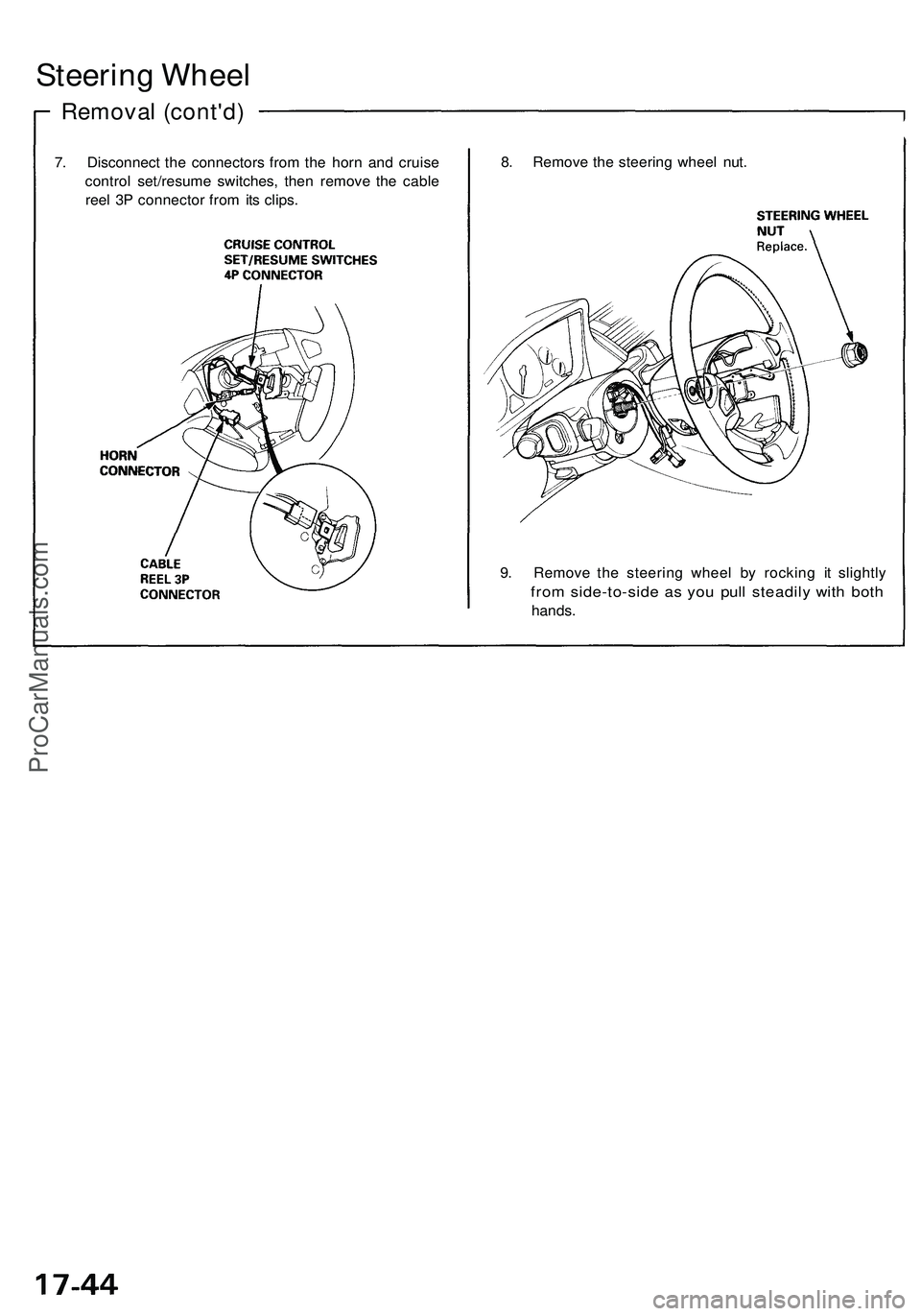
Steering Wheel
Removal (cont'd)
7. Disconnect the connectors from the horn and cruise
control set/resume switches, then remove the cable
reel 3P connector from its clips.
8. Remove the steering wheel nut.
9. Remove the steering wheel by rocking it slightly
from side-to-side as you pull steadily with both
hands.ProCarManuals.com
Page 917 of 1503
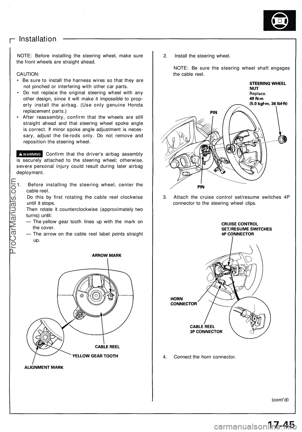
4. Connect the horn connector.
Installation
NOTE: Before installing the steering wheel, make sure
the front wheels are straight ahead.
CAUTION:
• Be sure to install the harness wires so that they are
not pinched or interfering with other car parts.
• Do not replace the original steering wheel with any
other design, since it will make it impossible to prop-
erly install the airbag. (Use only genuine Honda
replacement parts.)
• After reassembly, confirm that the wheels are still
straight ahead and that steering wheel spoke angle
is correct. If minor spoke angle adjustment is neces-
sary, adjust the tie-rods only. Do not remove and
reposition the steering wheel.
Confirm that the driver's airbag assembly
is securely attached to the steering wheel; otherwise,
severe personal injury could result during later airbag
deployment.
1. Before installing the steering wheel, center the
cable reel.
Do this by first rotating the cable reel clockwise
until it stops.
Then rotate it counterclockwise (approximately two
turns) until:
— The yellow gear tooth lines up with the mark on
the cover.
— The arrow on the cable reel label points straight
up.
2. Install the steering wheel.
NOTE: Be sure the steering wheel shaft engages
the cable reel.
3. Attach the cruise control set/resume switches 4P
connector to the steering wheel clips.ProCarManuals.com
Page 1442 of 1503
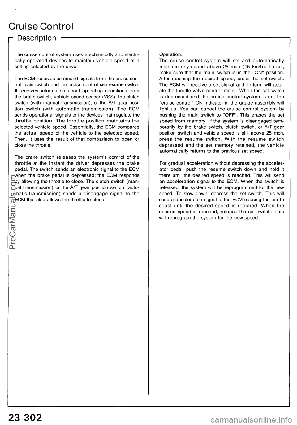
Cruise Contro l
Descriptio n
The cruis e contro l syste m use s mechanicall y an d electri -
call y operate d device s t o maintai n vehicl e spee d a t a
settin g selecte d b y th e driver .
Th e EC M receive s comman d signals from th e cruis e con -
trol mai n switc h an d th e cruis e contro l set/resum e switch.
I t receive s informatio n abou t operatin g condition s fro m
th e brak e switch , vehicl e spee d senso r (VSS) , th e clutc h
switch (wit h manua l transmission) , o r th e A/ T gea r posi -
tio n switc h (wit h automati c transmission) . Th e EC M
send s operationa l signal s t o th e device s tha t regulat e th e
throttl e position . Th e throttl e positio n maintain s th e
selecte d vehicl e speed . Essentially , th e EC M compare s
th e actua l spee d of the vehicl e t o th e selecte d speed .
Then , i t use s th e resul t of tha t compariso n t o ope n o r
clos e th e throttle .
Th e brak e switc h release s th e system' s contro l o f th e
throttl e a t th e instan t th e drive r depresse s th e brak e
pedal . Th e switc h send s a n electroni c signa l t o th e EC M
whe n th e brak e peda l i s depressed ; th e EC M respond s
b y allowin g th e throttl e t o close . Th e clutc h switc h (man -
ual transmission ) o r th e A/ T gea r positio n switc h (auto -
mati c transmission ) send s a disengag e signa l t o th e
EC M tha t als o allow s th e throttl e t o close . Operation
:
Th e cruis e contro l syste m wil l se t an d automaticall y
maintai n an y spee d abov e 2 5 mp h (4 5 km/h) . T o set ,
mak e sur e tha t th e mai n switc h i s i n th e "ON " position .
Afte r reachin g th e desire d speed , pres s th e se t switch .
Th e EC M wil l receiv e a se t signa l and , i n turn , wil l actu -
at e th e throttl e valv e contro l motor . Whe n th e se t switc h
i s depresse d an d th e cruis e contro l syste m is on , th e
"cruis e control " O N indicato r i n th e gaug e assembl y wil l
ligh t up . Yo u ca n cance l th e cruis e contro l syste m b y
pushin g th e mai n switc h t o "OFF" . Thi s erase s th e se t
spee d fro m memory . I f th e syste m is disengage d tem -
poraril y b y th e brak e switch , clutc h switch , o r A/ T gea r
positio n switc h an d vehicl e spee d i s stil l abov e 2 5 mph ,
pres s th e resum e switch . Wit h th e resum e switc h
depresse d an d th e se t memor y retained , th e vehicl e
automaticall y return s t o th e previou s se t speed .
Fo r gradua l acceleratio n withou t depressin g th e acceler -
ato r pedal , pus h th e resum e switc h dow n an d hol d i t
ther e unti l th e desire d spee d i s reached . Thi s wil l sen d
a n acceleratio n signa l t o th e ECM . Whe n th e switc h i s
released , th e syste m wil l b e reprogramme d fo r th e ne w
speed . T o slo w down , depres s th e se t switch . Thi s wil l
sen d a deceleratio n signa l t o th e EC M causin g th e ca r t o
coas t unti l th e desire d spee d i s reached . Whe n th e
desire d spee d i s reached , releas e th e se t switch . Thi s
wil l reprogra m th e syste m fo r th e ne w speed .
ProCarManuals.com
Page 1445 of 1503
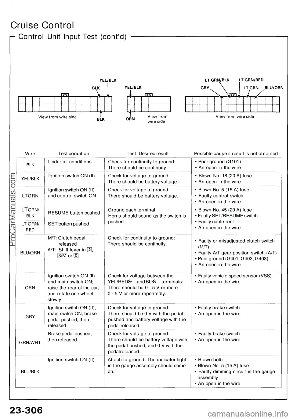
Cruise Contro l
Control Uni t Inpu t Tes t (cont'd )
WireTes t conditio n Test: Desire d resul t Possible caus e if resul t i s no t obtaine d
BLKUnde r al l condition sCheck fo r continuit y t o ground :
Ther e shoul d b e continuity . •
Poo r groun d (G101 )
• A n ope n i n th e wir e
YEL/BL KIgnition switc h O N (II )Chec k fo r voltag e t o ground :
Ther e shoul d b e batter y voltage . •
Blow n No . 1 8 (2 0 A ) fus e
• A n ope n i n th e wir e
LTGR N
Ignition switc h O N (II )
an d contro l switc h O N Chec
k fo r voltag e t o ground :
Ther e shoul d b e batter y voltage . •
Blow n No . 5 (1 5 A ) fus e
• Fault y contro l switc h
• A n ope n i n th e wir e
LT GRN /
BLKRESUM E butto n pushe d
LT GRN /
RED
SET butto n pushe d
Groun d eac h terminal :
Horn s shoul d soun d a s th e switc h i s
pushed . •
Blow n No . 4 5 (2 0 A ) fus e
• Fault y SET/RESUM E switc h
• Fault y cabl e ree l
• A n ope n i n th e wir e
BLU/OR N
M/T: Clutc h peda l
release d
A/T: Shif t leve r i n
o r
Chec k fo r continuit y t o ground :
Ther e shoul d b e continuity . •
Fault y o r misadjuste d clutc h switc h
(M/T)
• Fault y A/ T gea r positio n switc h (A/T )
• Poo r groun d (G401 , G402 , G403 )
• A n ope n i n th e wir e
ORN
Ignitio n switc h O N (II )
an d mai n switc h ON ;
raise th e rea r o f th e car ,
and rotat e on e whee l
slowly . Chec
k fo r voltag e betwee n th e
YEL/RE D an d BL K terminals :
Ther e shoul d b e 0 - 5 V or mor e -
0 - 5 V or mor e repeatedly . •
Fault y vehicl e spee d senso r (VSS )
• A n ope n i n th e wir e
GRY
Ignitio n switc h O N (II) ,
mai n switc h ON ; brak e
peda l pushed , the n
release d
Check fo r voltag e t o ground :
Ther e shoul d b e 0 V wit h th e peda l
pushe d an d batter y voltag e wit h th e
peda l released . •
Fault y brak e switc h
• A n ope n i n th e wir e
GRN/WH T
Brake peda l pushed ,
the n release d Chec
k fo r voltag e t o ground :
Ther e shoul d b e batter y voltag e wit h
th e peda l pushed , an d 0 V wit h th e
peda l released . •
Fault y brak e switc h
• A n ope n i n th e wir e
Ignitio n switc h O N (II )
BLU/BL K
Attach t o ground : Th e indicato r ligh t
i n th e gaug e assembl y shoul d com e
on.
• Blow n bul b
• Blow n No . 5 (1 5 A ) fus e
• Fault y dimmin g circui t i n th e gaug e
assembl y
• A n ope n i n th e wir e
ProCarManuals.com
Page 1447 of 1503
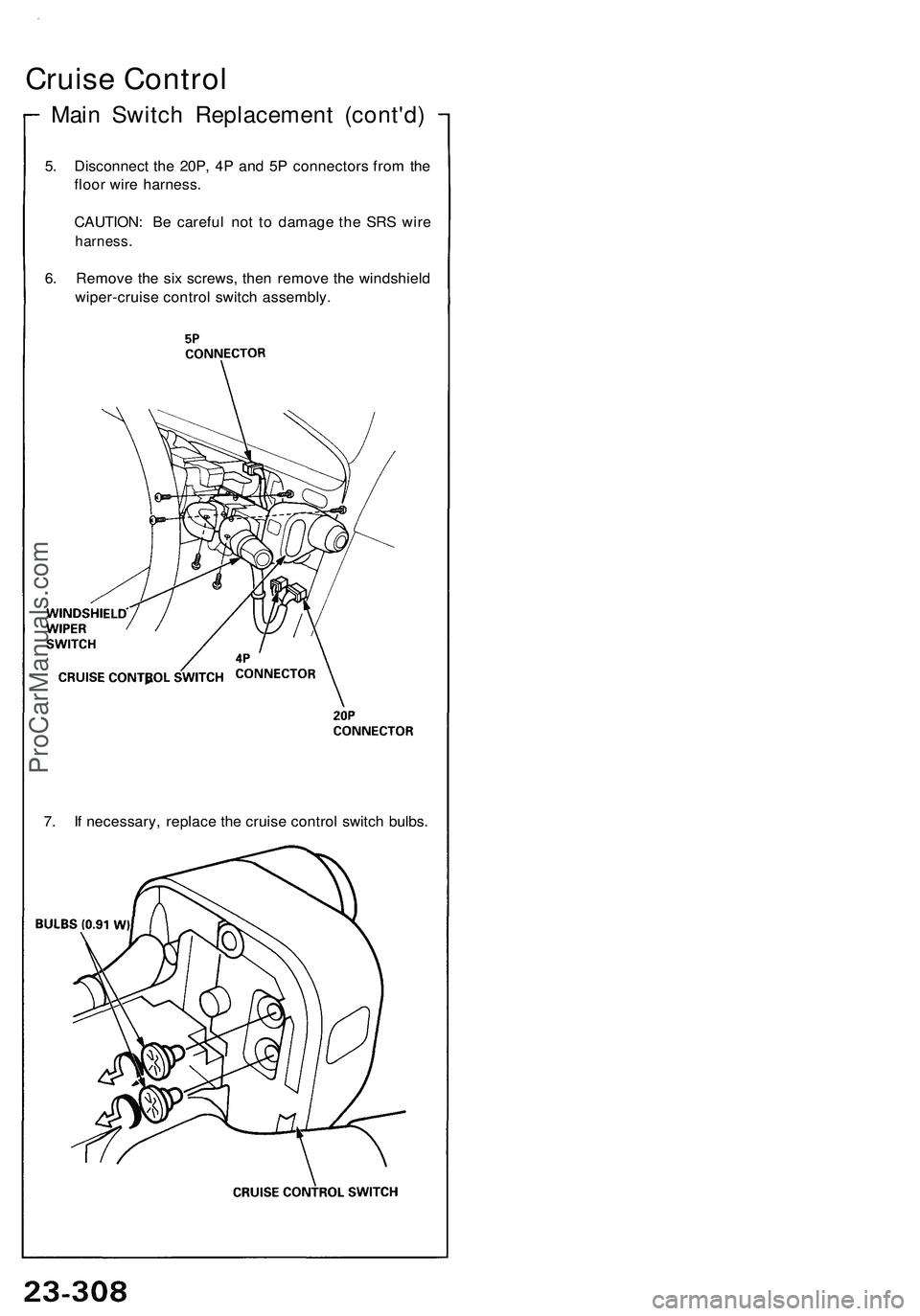
Main Switch Replacement (cont'd)
Cruise Control
5. Disconnect the 20P, 4P and 5P connectors from the
floor wire harness.
CAUTION: Be careful not to damage the SRS wire
harness.
6. Remove the six screws, then remove the windshield
wiper-cruise control switch assembly.
7. If necessary, replace the cruise control switch bulbs.ProCarManuals.com
Page 1494 of 1503
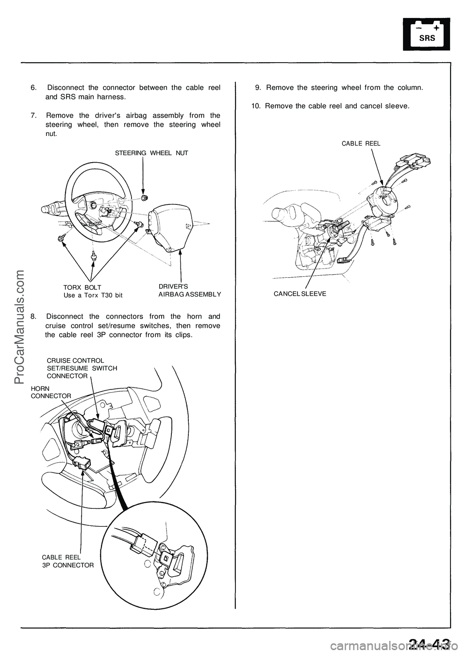
6. Disconnect the connector between the cable reel
and SRS main harness.
7. Remove the driver's airbag assembly from the
steering wheel, then remove the steering wheel
nut.
STEERING WHEEL NUT
TORX BOLT
Use a Torx T30 bit
DRIVER'S
AIRBAG ASSEMBLY
8. Disconnect the connectors from the horn and
cruise control set/resume switches, then remove
the cable reel 3P connector from its clips.
CRUISE CONTROL
SET/RESUME SWITCH
CONNECTOR
HORN
CONNECTOR
CABLE REEL
3P CONNECTOR
9. Remove the steering wheel from the column.
10. Remove the cable reel and cancel sleeve.
CABLE REEL
CANCEL SLEEVEProCarManuals.com
Page 1495 of 1503
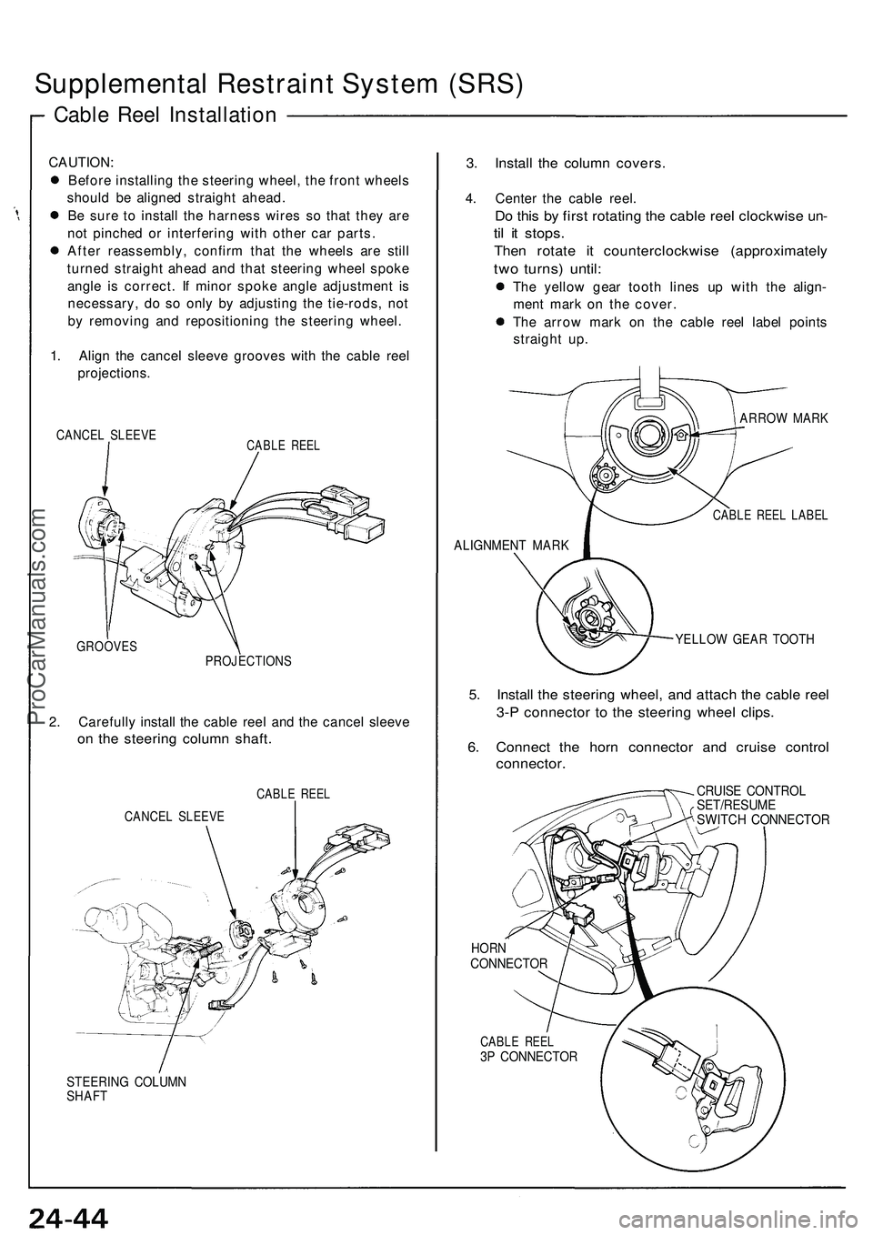
Supplemental Restraint System (SRS)
Cable Reel Installation
CAUTION:
Before installing the steering wheel, the front wheels
should be aligned straight ahead.
Be sure to install the harness wires so that they are
not pinched or interfering with other car parts.
After reassembly, confirm that the wheels are still
turned straight ahead and that steering wheel spoke
angle is correct. If minor spoke angle adjustment is
necessary, do so only by adjusting the tie-rods, not
by removing and repositioning the steering wheel.
1. Align the cancel sleeve grooves with the cable reel
projections.
CANCEL SLEEVE
CABLE REEL
GROOVES
PROJECTIONS
2. Carefully install the cable reel and the cancel sleeve
on the steering column shaft.
CABLE REEL
CANCEL SLEEVE
STEERING COLUMN
SHAFT
3. Install the column covers.
4. Center the cable reel.
Do this by first rotating the cable reel clockwise un-
til it stops.
Then rotate it counterclockwise (approximately
two turns) until:
The yellow gear tooth lines up with the align-
ment mark on the cover.
The arrow mark on the cable reel label points
straight up.
ARROW MARK
CABLE REEL LABEL
ALIGNMENT MARK
YELLOW GEAR TOOTH
5. Install the steering wheel, and attach the cable reel
3-P connector to the steering wheel clips.
6. Connect the horn connector and cruise control
connector.
CRUISE CONTROL
SET/RESUME
SWITCH CONNECTOR
HORN
CONNECTOR
CABLE REEL
3P CONNECTORProCarManuals.com