fuse box location ACURA NSX 1997 Service Repair Manual
[x] Cancel search | Manufacturer: ACURA, Model Year: 1997, Model line: NSX, Model: ACURA NSX 1997Pages: 1503, PDF Size: 57.08 MB
Page 1035 of 1503
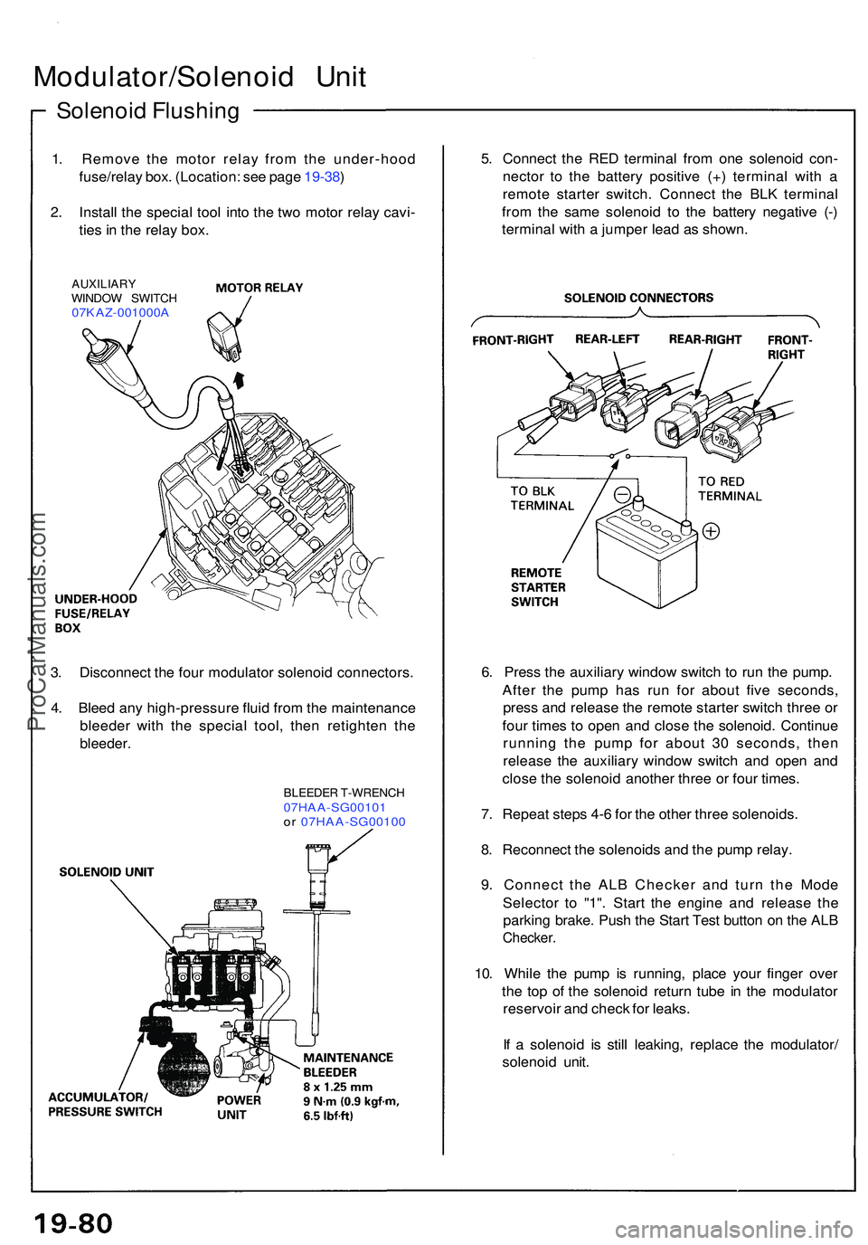
Solenoid Flushin g
Modulator/Solenoi d Uni t
1. Remov e th e moto r rela y fro m th e under-hoo d
fuse/rela y box . (Location : se e pag e 19-38 )
2 . Instal l th e specia l too l int o th e tw o moto r rela y cavi -
tie s in th e rela y box .
AUXILIAR YWINDOW SWITC H07KAZ-001000 A
5. Connec t th e RE D termina l fro m on e solenoi d con -
necto r t o th e batter y positiv e (+ ) termina l wit h a
remot e starte r switch . Connec t th e BL K termina l
fro m th e sam e solenoi d t o th e batter y negativ e (- )
termina l wit h a jumpe r lea d a s shown .
3 . Disconnec t th e fou r modulato r solenoi d connectors .
4 . Blee d an y high-pressur e flui d fro m th e maintenanc e
bleede r wit h th e specia l tool , the n retighte n th e
bleeder .
BLEEDE R T-WRENC H07HAA-SG0010 1or 07HAA-SG0010 0
6. Pres s th e auxiliar y windo w switc h t o ru n th e pump .
Afte r th e pum p ha s ru n fo r abou t fiv e seconds ,
pres s an d releas e th e remot e starte r switc h thre e o r
fou r time s t o ope n an d clos e th e solenoid . Continu e
runnin g th e pum p fo r abou t 3 0 seconds , the n
releas e th e auxiliar y windo w switc h an d ope n an d
clos e th e solenoi d anothe r thre e o r fou r times .
7 . Repea t step s 4- 6 fo r th e othe r thre e solenoids .
8 . Reconnec t th e solenoid s an d th e pum p relay .
9 . Connec t th e AL B Checke r an d tur n th e Mod e
Selecto r t o "1" . Star t th e engin e an d releas e th e
parkin g brake . Pus h th e Star t Tes t butto n o n th e AL B
Checker .
10. Whil e th e pum p i s running , plac e you r finge r ove r
th e to p o f th e solenoi d retur n tub e i n th e modulato r
reservoi r an d chec k fo r leaks .
I f a solenoi d i s stil l leaking , replac e th e modulator /
solenoi d unit .
ProCarManuals.com
Page 1185 of 1503
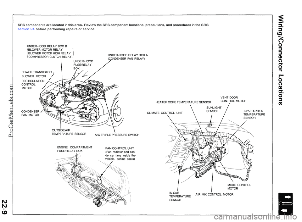
SRS component s ar e locate d in thi s area . Revie w th e SR S componen t locations , precautions , an d procedure s in th e SR S
sectio n 24 befor e performin g repair s o r service .
UNDER-HOO D RELA Y BO X BBLOWE R MOTO R RELA Y
BLOWE R MOTO R HIG H RELA Y
COMPRESSO R CLUTC H RELA Y
POWER TRANSISTO R
BLOWE R MOTO R
RECIRCULATIO N
CONTRO L
MOTO R
CONDENSE R
FA N MOTO R UNDER-HOO
D RELA Y BO X A
(CONDENSE R FA N RELAY )
HEATER COR E TEMPERATUR E SENSO R
CLIMAT E CONTRO L UNI T VEN
T DOO R
CONTRO L MOTO R
OUTSID E AI RTEMPERATUR E SENSO R
A/C TRIPL E PRESSUR E SWITC H
ENGIN E COMPARTMEN T
FUSE/RELA Y BO X
FAN CONTRO L UNI T(Fan radiato r an d con -
dense r fan s insid e th e
vehicle , behin d seats )
EVAPORATO RTEMPERATUR E
SENSO R
MOD E CONTRO L
MOTO R
IN-CA R
TEMPERATUR E
SENSO R AI
R MI X CONTRO L MOTO R
UNDER-HOO
D
FUSE/RELAYBOX
SUNLIGH TSENSOR
ProCarManuals.com
Page 1234 of 1503
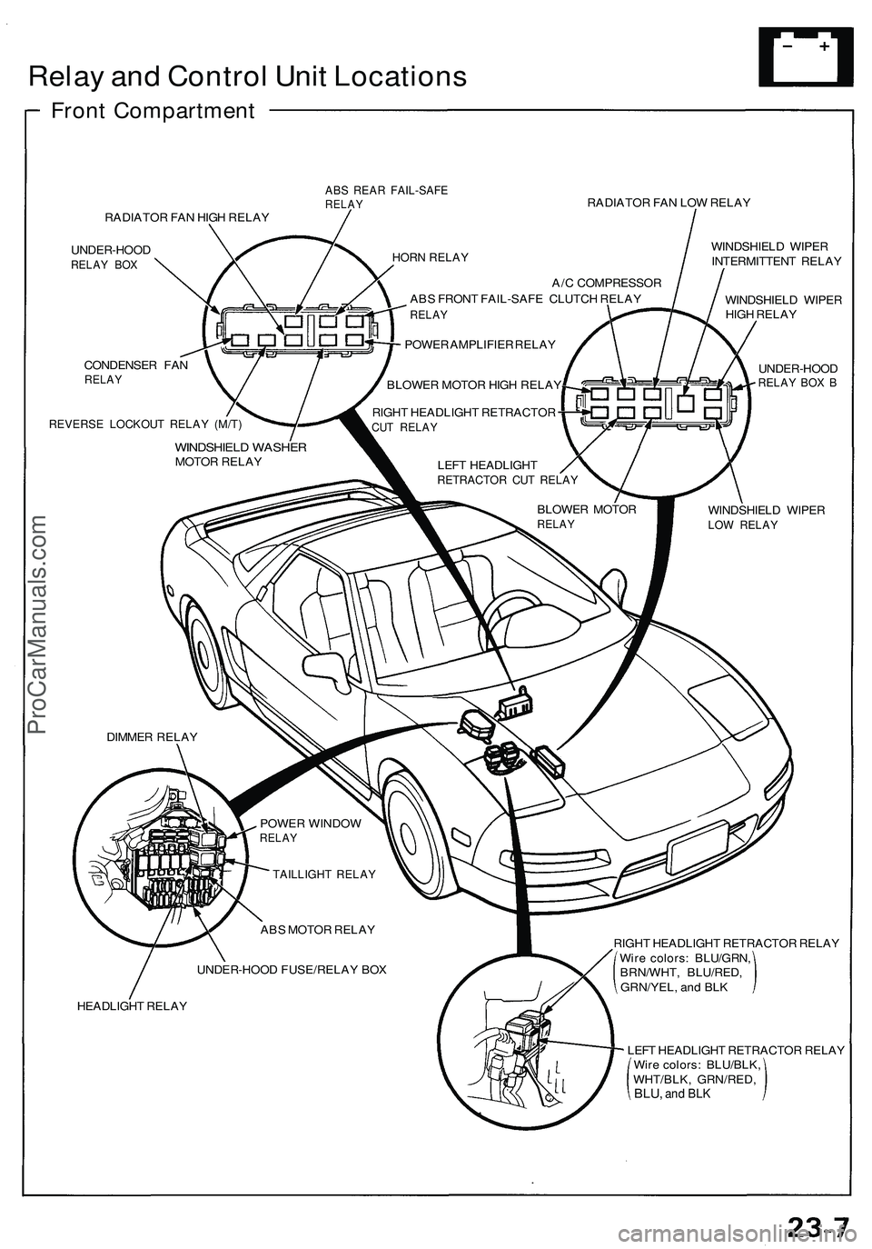
Relay and Control Unit Locations
Front Compartment
ABS REAR FAIL-SAFE
RELAY
RADIATOR FAN LOW RELAY
RADIATOR FAN HIGH RELAY
UNDER-HOOD
RELAY BOX
CONDENSER FAN
RELAY
REVERSE LOCKOUT RELAY (M/T)
WINDSHIELD WIPER
INTERMITTENT RELAY
WINDSHIELD WIPER
HIGH RELAY
UNDER-HOOD
RELAY BOX B
WINDSHIELD WIPER
LOW RELAY
A/C COMPRESSOR
ABS FRONT FAIL-SAFE CLUTCH RELAY
RELAY
POWER AMPLIFIER RELAY
BLOWER MOTOR HIGH RELAY
RIGHT HEADLIGHT RETRACTOR
CUT RELAY
WINDSHIELD WASHER
MOTOR RELAY
LEFT HEADLIGHT
RETRACTOR CUT RELAY
BLOWER MOTOR
RELAY
DIMMER RELAY
POWER WINDOW
RELAY
TAILLIGHT RELAY
ABS MOTOR RELAY
UNDER-HOOD FUSE/RELAY BOX
HEADLIGHT RELAY
HORN RELAY
RIGHT HEADLIGHT RETRACTOR RELAY
Wire colors: BLU/GRN,
BRN/WHT, BLU/RED,
GRN/YEL, and BLK
LEFT HEADLIGHT RETRACTOR RELAY
Wire colors: BLU/BLK,
WHT/BLK, GRN/RED,
BLU,
and BLKProCarManuals.com
Page 1235 of 1503
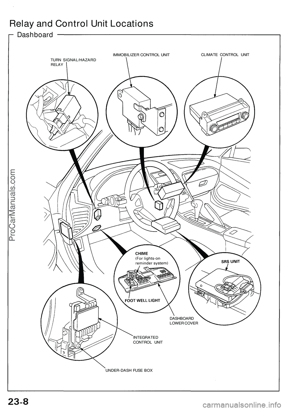
Relay and Control Unit Locations
Dashboard
IMMOBILIZER CONTROL UNIT
CLIMATE CONTROL UNIT
TURN SIGNAL/HAZARD
RELAY
DASHBOARD
LOWER COVER
INTEGRATED
CONTROL UNIT
UNDER-DASH FUSE BOXProCarManuals.com
Page 1243 of 1503
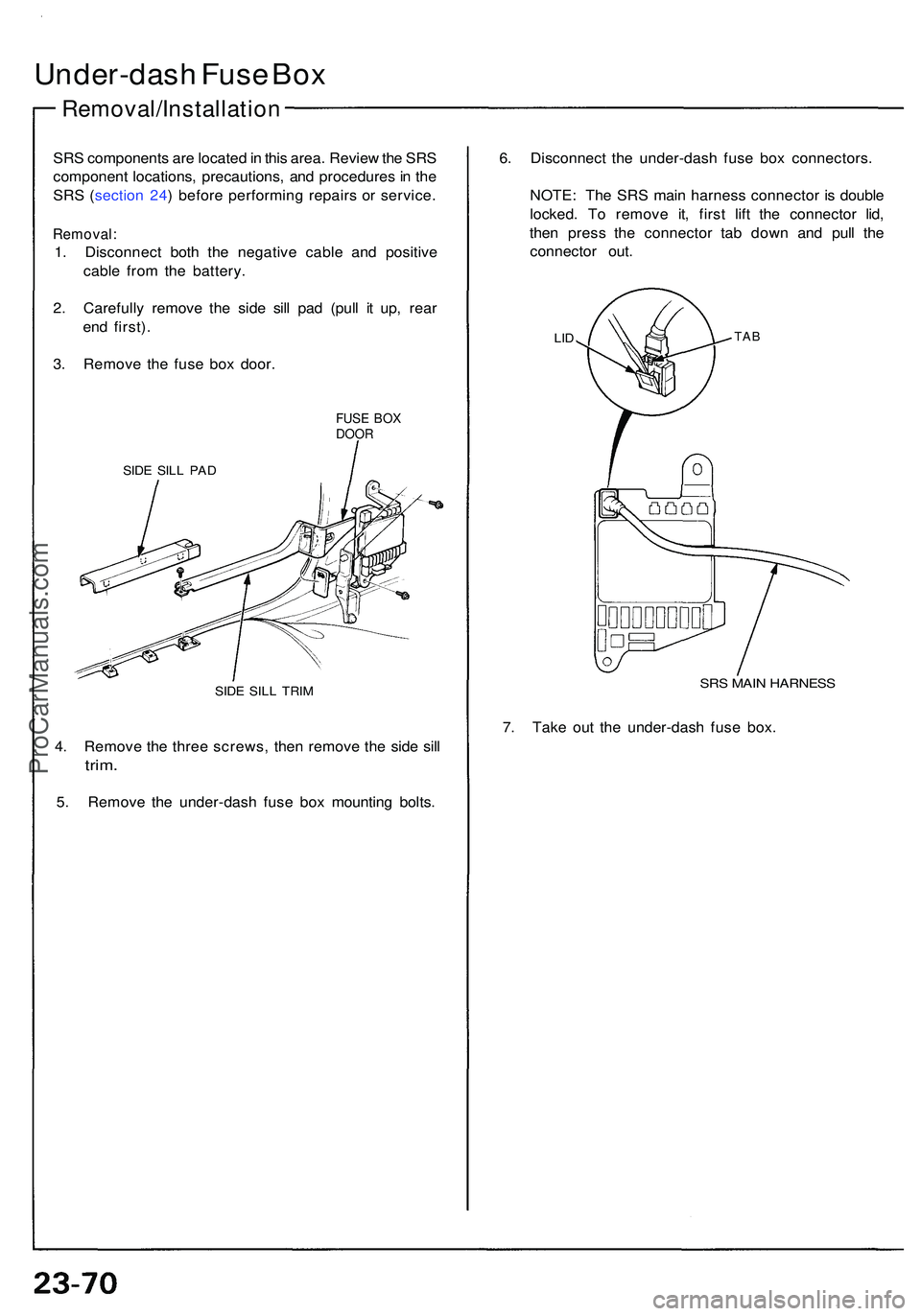
Under-dash Fus e Bo x
Removal/Installatio n
SRS component s ar e locate d in thi s area . Revie w th e SR S
componen t locations , precautions , an d procedure s in th e
SR S ( sectio n 24 ) befor e performin g repair s o r service .
Removal :
1. Disconnec t bot h th e negativ e cabl e an d positiv e
cabl e fro m th e battery .
2 . Carefull y remov e th e sid e sil l pa d (pul l i t up , rea r
en d first) .
3 . Remov e th e fus e bo x door .
FUSE BO XDOO R
SIDE SIL L PA D
SIDE SIL L TRI M
4. Remov e th e thre e screws , the n remov e th e sid e sil l
trim .
5. Remov e th e under-das h fus e bo x mountin g bolts . 6
. Disconnec t th e under-das h fus e bo x connectors .
NOTE : Th e SR S mai n harnes s connecto r i s doubl e
locked . T o remov e it , firs t lif t th e connecto r lid ,
the n pres s th e connecto r ta b dow n an d pul l th e
connecto r out .
LIDTA B
SRS MAI N HARNES S
7. Tak e ou t th e under-das h fus e box .
ProCarManuals.com
Page 1392 of 1503
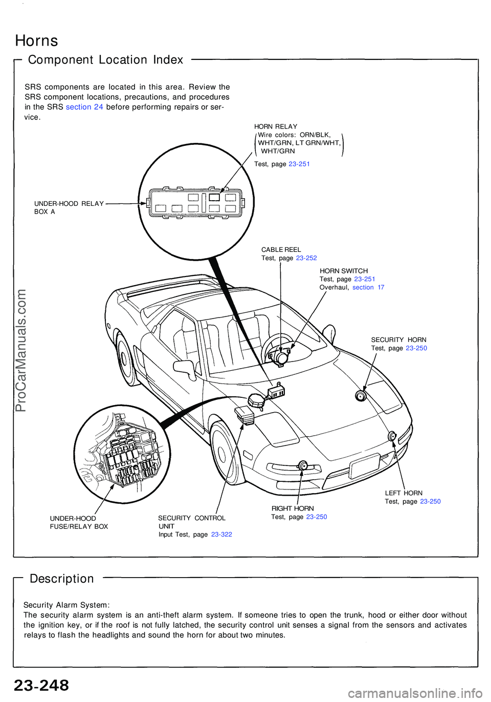
Horns
Componen t Locatio n Inde x
SRS component s ar e locate d i n thi s area . Revie w th e
SR S componen t locations , precautions , an d procedure s
i n th e SR S sectio n 24 befor e performin g repair s o r ser -
vice .
UNDER-HOO D RELA YBOX A
HOR N SWITC HTest, pag e 23-25 1
Overhaul , sectio n 1 7
CABL
E REE L
Test , pag e 23-25 2
SECURITY HOR N
Test , pag e 23-25 0
UNDER-HOO DFUSE/RELAY BO X SECURIT
Y CONTRO LUNITInpu t Test , pag e 23-32 2
RIGHT HOR NTest, pag e 23-25 0 LEF
T HOR N
Test , pag e 23-25 0
Descriptio n
Security Alar m System :
Th e securit y alar m syste m is a n anti-thef t alar m system . I f someon e trie s t o ope n th e trunk , hoo d o r eithe r doo r withou t
th e ignitio n key , o r i f th e roo f i s no t full y latched , th e securit y contro l uni t sense s a signa l fro m th e sensor s an d activate s
relay s t o flas h th e headlight s an d soun d th e hor n fo r abou t tw o minutes .
HORN RELA Y
Wir e colors : ORN/BLK ,
WHT/GRN, L T GRN/WHT ,, WHT/GR N
Test, pag e 23-25 1
ProCarManuals.com
Page 1452 of 1503
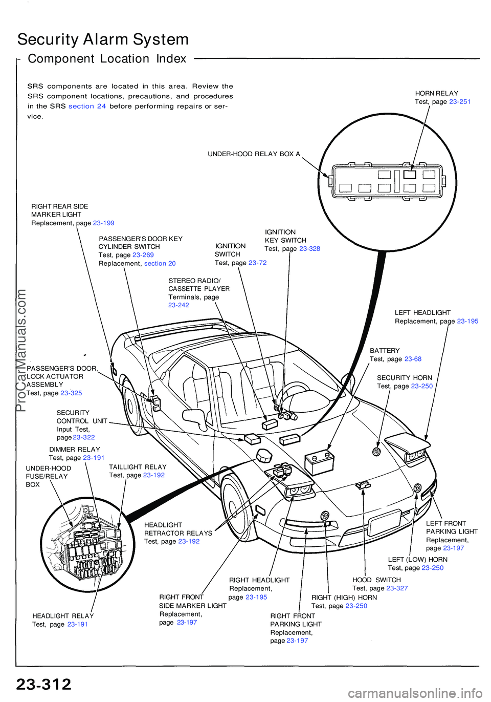
Security Alar m Syste m
- Componen t Locatio n Inde x
SRS component s ar e locate d i n thi s area . Revie w th e
SR S componen t locations , precautions , an d procedure s
i n th e SR S sectio n 24 befor e performin g repair s o r ser -
vice .
HOR N RELA Y
Test , pag e 23-25 1
UNDER-HOO D RELA Y BO X A
RIGH T REA R SID E
MARKE R LIGH T
Replacement , pag e 23-19 9
PASSENGER' S DOO R KE Y
CYLINDE R SWITC H
Test , pag e 23-26 9
Replacement , sectio n 2 0
IGNITIO NSWITCH
Test , pag e 23-7 2
IGNITIO NKEY SWITC H
Test , pag e 23-32 8
STERE O RADIO /
CASSETT E PLAYE RTerminals , pag e23-24 2LEFT HEADLIGH T
Replacement , pag e 23-19 5
PASSENGER' S DOOR .
LOC K ACTUATO R
ASSEMBLYTest, pag e 23-32 5
SECURIT YCONTROL UNI T
Inpu t Test ,
pag e 23-32 2
DIMME R RELA Y
Test , pag e 23-19 1
UNDER-HOO D
FUSE/RELAYBOX
TAILLIGH T RELA YTest, pag e 23-19 2
HEADLIGH T
RETRACTO R RELAY STest, pag e 23-19 2
RIGHT HEADLIGH T
Replacement ,
RIGH T FRON T pag e 23-19 5
SID E MARKE R LIGH T LEF
T FRON T
PARKIN G LIGH T
Replacement ,
pag e 23-19 7
LEF T (LOW ) HOR N
Test, pag e 23-25 0
HOOD SWITC H
Test , pag e 23-32 7
RIGH T (HIGH ) HOR N
Test , pag e 23-25 0
HEADLIGH T RELA YTest, pag e 23-19 1 Replacement
,
pag e 23-19 7 RIGH
T FRON TPARKIN G LIGH TReplacement ,
pag e 23-19 7 SECURIT
Y HOR N
Test , pag e 23-25 0
BATTER
Y
Test , pag e 23-6 8
ProCarManuals.com