stop start ACURA NSX 1997 Service Repair Manual
[x] Cancel search | Manufacturer: ACURA, Model Year: 1997, Model line: NSX, Model: ACURA NSX 1997Pages: 1503, PDF Size: 57.08 MB
Page 141 of 1503
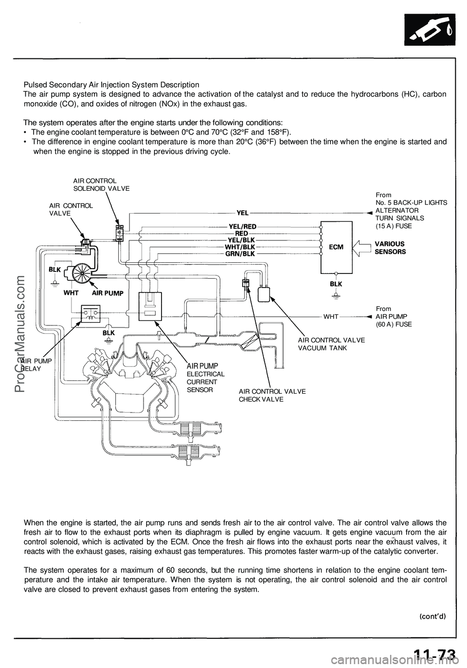
Pulsed Secondary Air Injection System Description
The air pump system is designed to advance the activation of the catalyst and to reduce the hydrocarbons (HC), carbon
monoxide (CO), and oxides of nitrogen (NOx) in the exhaust gas.
The system operates after the engine starts under the following conditions:
• The engine coolant temperature is between 0°C and 70°C (32°F and 158°F).
• The difference in engine coolant temperature is more than 20°C (36°F) between the time when the engine is started and
when the engine is stopped in the previous driving cycle.
AIR CONTROL
SOLENOID VALVE
AIR CONTROL
VALVE
WHT
AIR PUMP
RELAY
From
No. 5 BACK-UP LIGHTS
ALTERNATOR
TURN SIGNALS
(15 A) FUSE
From
AIR PUMP
(60 A) FUSE
AIR CONTROL VALVE
VACUUM TANK
AIR CONTROL VALVE
CHECK VALVE
When the engine is started, the air pump runs and sends fresh air to the air control valve. The air control valve allows the
fresh air to flow to the exhaust ports when its diaphragm is pulled by engine vacuum. It gets engine vacuum from the air
control solenoid, which is activated by the ECM. Once the fresh air flows into the exhaust ports near the exhaust valves, it
reacts with the exhaust gases, raising exhaust gas temperatures. This promotes faster warm-up of the catalytic converter.
The system operates for a maximum of 60 seconds, but the running time shortens in relation to the engine coolant tem-
perature and the intake air temperature. When the system is not operating, the air control solenoid and the air control
valve are closed to prevent exhaust gases from entering the system.
AIR PUMP
ELECTRICAL
CURRENT
SENSORProCarManuals.com
Page 145 of 1503
Troubleshooting Precaution s
EPS Indicato r Ligh t
Unde r norma l conditions , th e EP S indicato r i n th e gaug e assembl y come s o n whe n th e ignitio n switc h is turne d t o th e O N
(II ) position , the n goe s of f afte r th e engin e i s started . Thi s indicate s tha t th e bul b an d it s circuit s ar e operatin g correctly . I f
ther e i s an y troubl e i n th e system , th e EP S indicato r turn s o n durin g driving , an d th e powe r steerin g assis t i s turne d off .
Whe n th e EP S indicato r come s on , th e contro l uni t memorize s th e DTC . I n thi s case , th e contro l uni t doe s no t activat e th e
EP S syste m afte r th e engin e start s agai n bu t i t keep s th e EP S indicato r on .
Whe n a proble m is detected , th e EP S indicato r come s on . Unde r som e conditio n th e indicato r stay s o n unti l th e ignitio n switc h
i s turne d OFF . Unde r othe r conditions , however , th e indicato r goe s of f automaticall y whe n th e syste m return s to normal .
Fo r DTC s 2 3 an d 31 , th e indicato r goe s of f automaticall y whe n th e syste m return s t o normal . Fo r al l othe r codes , th e indicato r
stay s in unti l th e ignitio n switc h is turne d OFF .
Fo r DTC s 2 4 an d 25 , th e EP S indicato r goe s of f whe n th e syste m is O K afte r th e ignitio n switc h is turne d fro m OF F to O N
(ID .
Diagnosti c Troubl e Cod e (DTC )
• Th e lowes t DT C is indicate d first .
• Th e DTC s continu e blinkin g unti l th e ignitio n switc h i s turne d off .
• Th e DTC s ar e erase d fro m th e contro l uni t whe n th e EP S contro l uni t VB U powe r suppl y o r connecto r i s disconnected .
• Th e EP S syste m ca n b e rese t an d th e contro l unit' s memor y ca n b e erase d b y disconnectin g th e CLOC K (7. 5 A ) fus e fo r
mor e tha n te n second s (excep t DTC s 2 4 an d 25) .
Self-diagnosis :
The CP U (centra l processin g unit ) control s th e followin g whe n it detect s a proble m durin g self-diagnosis :
1 . Turn s th e EP S indicato r O N to aler t th e driver .
2 . Powe r assis t stops , an d norma l manua l steerin g operatio n resume s (excep t DT C 33) .
3 . Th e EP S contro l uni t memorize s th e diagnosti c troubl e cod e (DTC) .
4 . Afte r th e DT C is store d in th e contro l unit , th e CP U stop s self-diagnosis .
Troubleshooting :
• Befor e startin g th e troubleshooting , clea r th e DT C b y disconnectin g th e CLOC K (7. 5 A ) fus e fo r te n second s o r more ,
an d test-driv e th e vehicle . Chec k tha t th e sympto m o f th e troubl e appear s again , an d the n troubleshoot . I f th e proble m
i s a n intermitten t problem , th e syste m doe s no t becom e activ e afte r th e engin e start s eve n thoug h th e proble m is
solved .
• Whe n bot h EP S indicato r an d A/ T "D " indicato r com e on , perfor m th e A/ T troubleshootin g first .
• Whe n th e customer' s reporte d proble m canno t b e verifie d i n th e car , as k th e custome r abou t th e condition s whe n th e
EP S indicato r cam e ON , the n test-driv e th e ca r unde r thos e conditions , i f possible . I f th e EP S indicato r doe s no t com e
O N durin g th e test , chec k fo r loos e connection s o r poo r contact s a t th e connector s b y wigglin g th e harness , etc .
• Th e connecto r termina l number s ar e viewe d fro m th e wir e sid e fo r th e femal e terminal s an d fro m th e termina l sid e fo r
th e mal e terminals .
• Afte r th e repair , test-driv e th e ca r an d chec k tha t th e EP S indicato r doe s no t com e O N agai n durin g th e test . (Refe r t o
th e Symptom-to-Syste m Char t fo r diagnosti c period. )
ProCarManuals.com
Page 146 of 1503
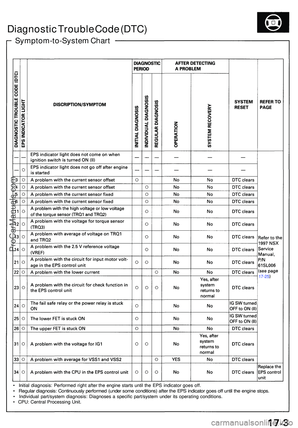
Symptom-to-System Char t
Diagnosti c Troubl e Cod e (DTC )
• Initia l diagnosis : Performe d righ t afte r th e engin e start s unti l th e EP S indicato r goe s off .
• Regula r diagnosis : Continuousl y performe d (unde r som e conditions ) afte r th e EP S indicato r goe s of f unti l th e engin e stops .
• Individua l part/syste m diagnosis: Diagnoses a specifi c part/syste m unde r it s operatin g conditions .
• CPU : Centra l Processin g Unit .
17-25
ProCarManuals.com
Page 151 of 1503
Troubleshooting Precaution s
ABS Indicato r
1. I f th e syste m is OK , th e AB S indicato r come s o n fo r tw o second s (initia l tur n on ) afte r turnin g th e ignitio n switc h O N (II) ,
the n th e AB S indicato r goe s off . Afte r tha t time , th e AB S indicato r come s o n agai n afte r startin g th e engine , the n th e
AB S indicato r goe s of f tw o second s afte r th e ignitio n switc h retur n t o O N (II) . Thi s occur s becaus e th e AB S contro l uni t
activate s b y th e powe r sourc e circui t tha t i s connecte d onl y whe n th e ignitio n switc h is O N (II) .
2 . I f a proble m occurs , th e Centra l Processin g Uni t (CPU ) diagnose s th e proble m are a an d th e proble m condition , the n th e
CP U memorize s th e Diagnosti c Troubl e Cod e (DTC ) an d turn s o n th e AB S indicator . I f th e syste m is OK , th e AB S indicato r
doe s no t com e o n excep t whe n th e ignitio n switc h is initiall y turne d on .
3 . I f th e proble m is detecte d intermittentl y o r continuously , th e AB S indicato r indicatio n patter n i s differen t a s describe d
below .
• DT C 61 o r 62 :
The AB S indicato r come s o n whe n a proble m is detecte d in ever y tim e th e syste m is activated , an d th e AB S indicato r
goe s of f whe n th e syste m return s t o normal .
• DT C 11 , 13 , 15 , 17 , 31 , 32 , 33 , 34 , 35 , 36 , 37 , 38 , 54 , 7 1 o r 81 :
The AB S indicato r come s o n whe n a proble m is detecte d in ever y tim e th e syste m is activated , an d th e AB S indicato r
continue s o n unti l th e ignitio n switc h is turne d OF F regardles s o f th e syste m return s t o norma l o r not .
• DT C 12 , 14 , 16 , 18 , 21 , 22 , 23 , 24 , 41 , 42 , 43 , 44 , 51 , 5 2 o r 53 :
The AB S indicato r come s o n whe n a proble m is detected , an d th e AB S indicato r continue s o n unti l th e ignitio n switc h
i s turne d OFF . Th e AB S indicato r goe s of f whe n th e syste m is activate d th e nex t time .
4 . Th e AB S indicato r come s o n whe n th e AB S contro l uni t detect s a proble m in th e system . However , eve n thoug h th e
syste m is operatin g properly , th e AB S indicato r wil l com e on , unde r th e followin g conditions . T o determin e th e actua l
caus e o f problem , questio n th e custome r abou t th e problem , takin g thes e condition s int o consideration .
• Onl y driv e whee l (o r wheels ) rotat e
• On e driv e whee l i s stuc k
• Vehicl e spi n
• AB S continuou s operat e fo r a lon g tim e
• Signa l disturbanc e
Diagnosti c Troubl e Cod e (DTC )
1 . I f a proble m occur s i n th e system , th e Centra l Processin g Uni t (CPU ) diagnose s th e proble m are a an d th e proble m
condition , the n th e CP U memorize s th e Diagnosti c Troubl e Cod e (DTC ) int o th e EEPRO M (non-volatil e memory) .
2 . Th e DT C clearin g i s possibl e onl y whe n performin g th e specifie d procedures , an d th e DT C is no t cleare d unde r th e
followin g conditions .
• Turnin g th e ignitio n switc h of f o r disconnectin g th e batter y termina l
• Th e syste m return s t o norma l
3 . Th e memor y ca n hol d an y numbe r o f DTCs . However , whe n th e sam e DT C is detecte d mor e tha n once , th e late r on e is
writte n ove r th e previou s one . Therefore , whe n th e sam e proble m is detecte d repeatedly , i t i s memorize d a s on e DTC .
4 . Th e DTC s ar e indicate d in th e orde r o f ascendin g number , no t i n th e orde r the y occur .
5 . Perfor m th e specifie d procedure s t o indicat e th e DTCs .
Self-diagnosi s
1. Self-diagnosi s can b e classified into tw o categories .
• Initia l diagnosis : Performe d righ t afte r th e engin e start s an d unti l th e AB S indicato r goe s off .
• Regula r diagnosis : Performe d righ t afte r th e initia l diagnosi s an d unti l th e ignitio n switc h i s turne d off .
2 . Whe n a proble m is detecte d b y self-diagnosis , th e syste m
• Turn s th e AB S indicato r O N
• Memorize s th e DT C
• Stop s AB S contro l
ProCarManuals.com
Page 194 of 1503
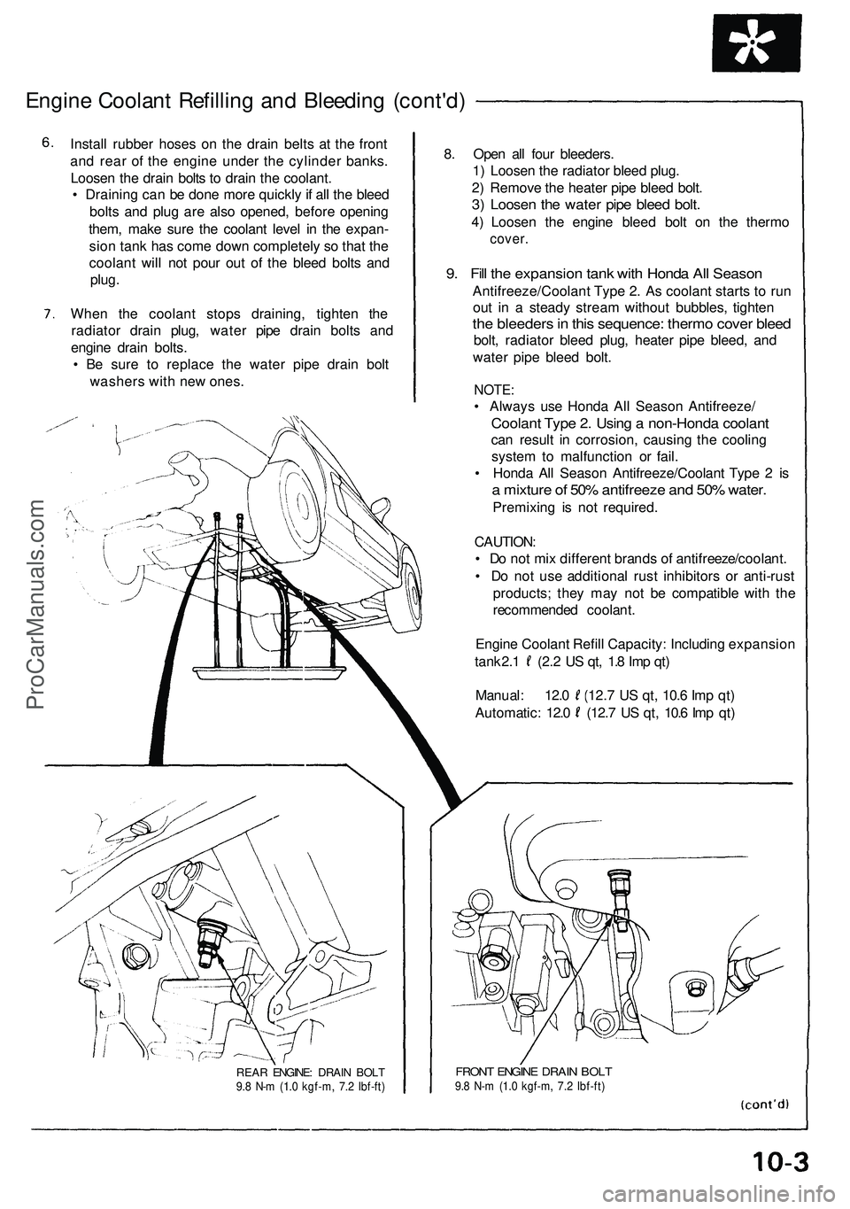
Engine Coolan t Refillin g an d Bleedin g (cont'd )
Install rubbe r hose s o n th e drai n belt s a t th e fron t
an d rea r o f th e engin e unde r th e cylinde r banks .
Loose n th e drai n bolt s t o drai n th e coolant .
• Drainin g ca n b e don e mor e quickl y if al l th e blee d
bolt s an d plu g ar e als o opened , befor e openin g
them , mak e sur e th e coolan t leve l i n th e expan -
sio n tan k ha s com e dow n completel y s o tha t th e
coolan t wil l no t pou r ou t o f th e blee d bolt s an d
plug .
Whe n th e coolan t stop s draining , tighte n th e
radiato r drai n plug , wate r pip e drain bolt s an d
engin e drai n bolts .
• B e sur e t o replac e th e wate r pip e drai n bol t
washer s wit h ne w ones . 8
. Ope n al l fou r bleeders .
1 ) Loose n th e radiato r blee d plug .
2 ) Remov e th e heate r pip e blee d bolt .
3) Loose n th e wate r pip e blee d bolt .
4) Loose n th e engin e blee d bol t o n th e therm o
cover.
9. Fil l th e expansio n tan k wit h Hond a Al l Seaso n
Antifreeze/Coolan t Typ e 2 . A s coolan t start s t o ru n
ou t i n a stead y strea m withou t bubbles , tighte n
the bleeder s in thi s sequence : therm o cove r blee d
bolt, radiato r blee d plug , heate r pip e bleed , an d
wate r pip e blee d bolt .
NOTE :
• Alway s us e Hond a Al l Seaso n Antifreeze /
Coolant Typ e 2 . Usin g a non-Hond a coolan t
can resul t i n corrosion , causin g th e coolin g
syste m to malfunctio n o r fail .
• Hond a Al l Seaso n Antifreeze/Coolan t Typ e 2 is
a mixtur e o f 50 % antifreez e an d 50 % water .
Premixin g i s no t required .
CAUTION :
• D o no t mi x differen t brand s o f antifreeze/coolant .
• D o no t us e additiona l rus t inhibitor s o r anti-rus t
products ; the y ma y no t b e compatibl e wit h th e
recommende d coolant .
Engin e Coolan t Refil l Capacity : Includin g expansio n
tank 2. 1 (2. 2 U S qt , 1. 8 Im p qt )
Manual : 12. 0 (12. 7 U S qt , 10. 6 Im p qt )
Automatic : 12. 0 (12. 7 U S qt , 10. 6 Im p qt )
REA R ENGINE : DRAI N BOL T9.8 N- m (1. 0 kgf-m , 7. 2 Ibf-ft )FRON T ENGIN E DRAI N BOL T9.8 N- m (1. 0 kgf-m , 7. 2 Ibf-ft )
ProCarManuals.com
Page 584 of 1503
Troubleshooting
How to Read Flowcharts
A flowchart is designed to be used from start to final repair. It's like a map showing you the shortest distance. But beware:
if you go off the "map" anywhere but a "stop" symbol, you can easily get lost.
Describes the conditions or situation to start a troubleshooting flowchart.
Asks you to do something; perform a test, set up a condition etc.
Asks you about the result of an action, then sends you in the appropriate troubleshooting direction.
NOTE:
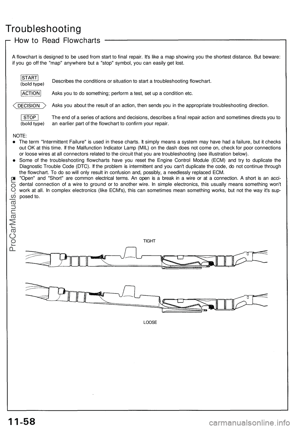
The term "Intermittent Failure" is used in these charts. It simply means a system may have had a failure, but it checks
out OK at this time. If the Malfunction Indicator Lamp (MIL) on the dash does not come on, check for poor connections
or loose wires at all connectors related to the circuit that you are troubleshooting (see illustration below).
Some of the troubleshooting flowcharts have you reset the Engine Control Module (ECM) and try to duplicate the
Diagnostic Trouble Code (DTC). If the problem is intermittent and you can't duplicate the code, do not continue through
the flowchart. To do so will only result in confusion and, possibly, a needlessly replaced ECM.
"Open" and "Short" are common electrical terms. An open is a break in a wire or at a connection. A short is an acci-
dental connection of a wire to ground or to another wire. In simple electronics, this usually means something won't
work at all. In complex electronics (like ECM's), this can sometimes mean something works, but not the way it's sup-
posed to.
TIGHT
LOOSE
The end of a series of actions and decisions, describes a final repair action and sometimes directs you to
an earlier part of the flowchart to confirm your repair.ProCarManuals.com
Page 586 of 1503
PGM-FI System
System Description (cont'd)
3. Fuel Cut-off Control
During deceleration with the throttle valve closed, current to the fuel injectors is cut off to improve fuel economy at
speeds over 1,500 rpm.
Fuel cut-off action also takes place when engine speed exceeds 8,300 rpm, regardless of the position of the throttle
valve, to protect the engine from over-revving.
4. A/C Compressor Clutch Relay
When the ECM receives a demand for cooling from the air conditioning system, it delays the compressor from being
energized, and enriches the mixture to assure smooth translation to the A/C mode.
5. Evaporative Emission (EVAP) Purge Control Solenoid Valve
When the engine coolant temperature is below 153°F (67°C), the ECM controls the EVAP purge control solenoid valve
which cuts vacuum to the EVAP purge control canister diaphragm.
6. Intake Air Bypass (IAB) Control Solenoid Valve
When the engine speed is below 4,800 rpm, the IAB control solenoid valve is activated by a signal from the ECM. Intake
air then flows through the smaller chamber, and high torque is delivered. To increase air flow at engine speeds higher
than 4,800 rpm, the solenoid valve is deactivated by the ECM, and the intake air flows through the larger chamber.
7. Exhaust Gas Recirculation (EGR) Control Solenoid Valve
When the EGR is required for control of oxides of nitrogen (NOx) emissions, the ECM supplies ground to the EGR
control solenoid valve which supplies regulated vacuum to the EGR valve.
ECM Fail-safe/Back-up Functions
1. Fail-Safe Function
When an abnormality occurs in a signal from a sensor, the ECM ignores that signal and assumes a pre-programmed
valve for that sensor that allows the engine to continue to run.
2. Back-up Function
When an abnormality occurs in the ECM itself, the fuel injectors are controlled by a back-up circuit independent of the
system in order to permit minimal driving.
3. Self-diagnosis Function [Malfunction Indicator Lamp (MIL)]
When an abnormality occurs in a signal from a sensor, the ECM lights the MIL and stores the diagnostic trouble code
in erasable memory. When the ignition is initially turned on, the ECM supplies ground for the MIL for two seconds to
check the MIL bulb condition.
4. Two Trip Detection Method
To prevent false indications, the Two Trip Detection Method is used for the H02S, fuel metering-related, idle control
system, ECT sensor, EGR system self-diagnostic functions and EVAP control system. When an abnormality occurs,
the ECM stores it in its memory. When the same abnormality recurs after the ignition switch is turned OFF and ON (II)
again, the ECM informs the driver by lighting the MIL.
However, to ease troubleshooting, this function is cancelled when you short the service check connector. The MIL will
then blink immediately when an abnormality occurs.
5. Two (or three) Driving Cycle Detection Method
A "Driving Cycle" consists of starting the engine, beginning closed loop operation, and stopping the engine. If misfir-
ing that increases emissions or EVAP control system malfunction is detected during two consecutive driving cycles,
or TWC deterioration is detected during three consecutive driving cycles, the ECM turns the MIL on.
However,
to
ease
troubleshooting,
this
function
is
cancelled when
you
short
the
service check connector.
The MIL
will
then blink immediately when an abnormality occurs.ProCarManuals.com
Page 714 of 1503
(cont'd)
Description
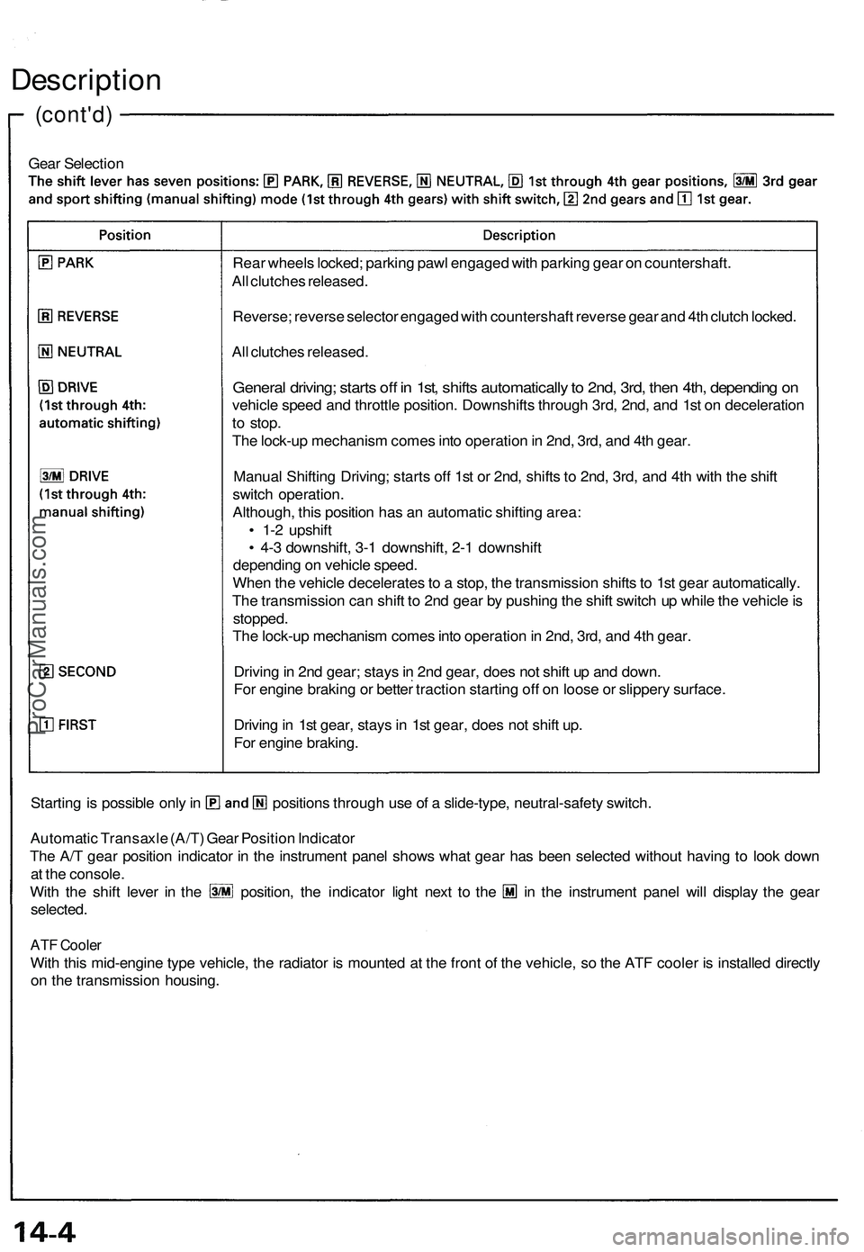
Gear Selection
Starting is possible only in positions through use of a slide-type, neutral-safety switch.
Automatic Transaxle (A/T) Gear Position Indicator
The A/T gear position indicator in the instrument panel shows what gear has been selected without having to look down
at the console.
With the shift lever in the position, the indicator light next to the in the instrument panel will display the gear
selected.
ATF Cooler
With this mid-engine type vehicle, the radiator is mounted at the front of the vehicle, so the ATF cooler is installed directly
on the transmission housing.
Rear wheels locked; parking pawl engaged with parking gear on countershaft.
All clutches released.
Reverse; reverse selector engaged with countershaft reverse gear and 4th clutch locked.
All clutches released.
General driving; starts off in 1st, shifts automatically to 2nd, 3rd, then 4th, depending on
vehicle speed and throttle position. Downshifts through 3rd, 2nd, and 1st on deceleration
to stop.
The lock-up mechanism comes into operation in 2nd, 3rd, and 4th gear.
Manual Shifting Driving; starts off 1st or 2nd, shifts to 2nd, 3rd, and 4th with the shift
switch operation.
Although, this position has an automatic shifting area:
• 1-2 upshift
• 4-3 downshift, 3-1 downshift, 2-1 downshift
depending on vehicle speed.
When the vehicle decelerates to a stop, the transmission shifts to 1st gear automatically.
The transmission can shift to 2nd gear by pushing the shift switch up while the vehicle is
stopped.
The lock-up mechanism comes into operation in 2nd, 3rd, and 4th gear.
Driving in 2nd gear; stays in 2nd gear, does not shift up and down.
For engine braking or better traction starting off on loose or slippery surface.
Driving in 1st gear, stays in 1st gear, does not shift up.
For engine braking.ProCarManuals.com
Page 726 of 1503
Electronic Control System (cont'd)
Description
• Automatic shifting control in Sport Shifting mode
This position also has automatic shifting areas:
• 1-2 upshift
• 4-3 downshift, 3-1 downshift, 2-1 downshift
depending on vehicle speed. To prevent engine over-revving, the transmission has a 1-2 automatic upshift speed, and 4-3,
3-1, 2-1 downshift allowable speeds.
• When the vehicle reaches the 1-2 automatic upshift speed, the TCM outputs the 1-2 upshift signal to the transmis-
sion and the transmission upshifts to 2nd from 1st gear.
• When the vehicle is coasting over the 4-3 downshift allowable speed and 3-2 downshift allowable speed, the TCM
does not input the downshift signal from the shift switch, and the transmission does not downshift.
• When the vehicle is coasting over the 2-1 downshift allowable speed in 2nd gear, the TCM inputs the signal to wait
until it reaches the 2-1 downshift allowable speed, then the shift indicator blinks to indicate it is waiting to downshift
to
1st.
When the vehicle decelerates to a stop, the transmission shifts to 1st gear automatically.
The transmission can be shifted to 2nd gear by pushing the shift switch up while the vehicle is stopped. This allows the
vehicle to start off in 2nd gear.
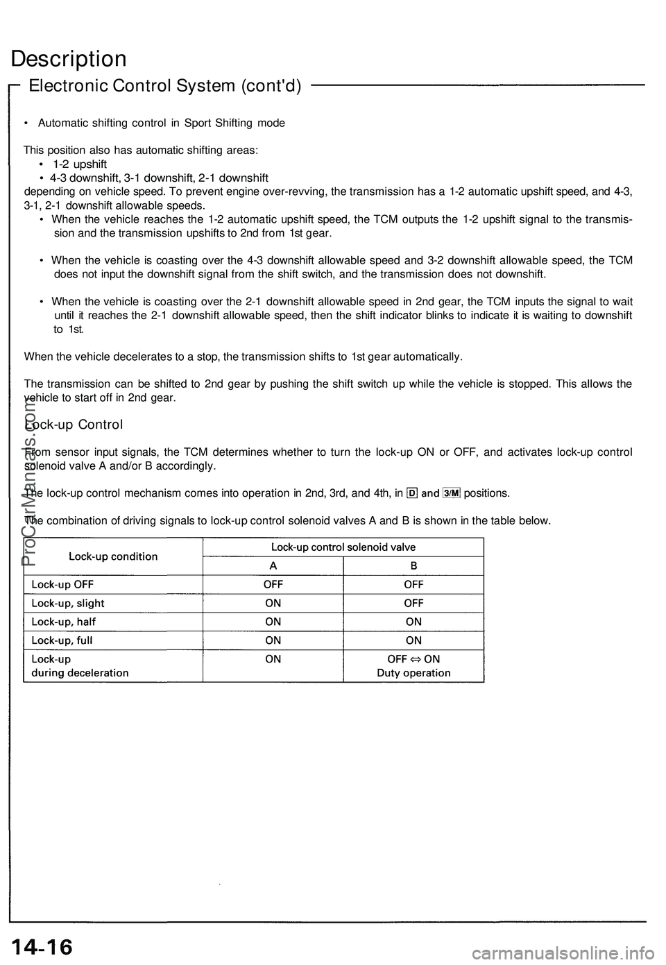
Lock-up Control
From sensor input signals, the TCM determines whether to turn the lock-up ON or OFF, and activates lock-up control
solenoid valve A and/or B accordingly.
The lock-up control mechanism comes into operation in 2nd, 3rd, and 4th, in positions.
The combination of driving signals to lock-up control solenoid valves A and B is shown in the table below.ProCarManuals.com
Page 771 of 1503
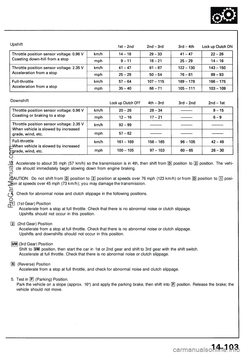
Upshift
Downshift
3. Accelerate to about 35 mph (57 km/h) so the transmission is in 4th, then shift from position to position. The vehi-
cle should immediately begin slowing down from engine braking.
CAUTION: Do not shift from position to position at speeds over 76 mph (123 km/h) or from position to posi-
tion at speeds over 45 mph (73 km/h); you may damage the transmission.
4. Check for abnormal noise and clutch slippage in the following positions.
(1st Gear) Position
Accelerate from a stop at full throttle. Check that there is no abnormal noise or clutch slippage.
Upshifts should not occur in this position.
(2nd Gear) Position
Accelerate from a stop at full throttle. Check that there is no abnormal noise or clutch slippage.
Upshifts and downshifts should not occur in this position.
(3rd Gear) Position
Shift to position, then start the car in 1st or 2nd gear and shift to 3rd gear with the shift switch.
Accelerate at full throttle. Check that there is no abnormal noise or clutch slippage.
(Reverse) Position
Accelerate from a stop at full throttle, and check for abnormal noise and clutch slippage.
5. Test in (Parking) Position.
Park the vehicle on a slope (approx. 16°) and apply the parking brake, then shift into position. Release the brake; the
vehicle should not move.ProCarManuals.com