width ACURA NSX 1997 Service Repair Manual
[x] Cancel search | Manufacturer: ACURA, Model Year: 1997, Model line: NSX, Model: ACURA NSX 1997Pages: 1503, PDF Size: 57.08 MB
Page 367 of 1503
3-2
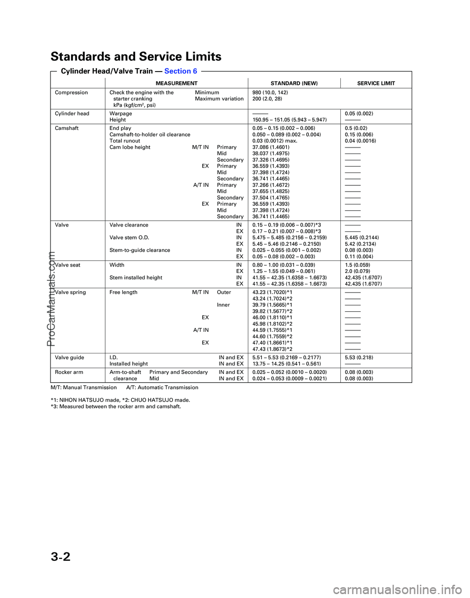
Standards and Service Limits
MEASUREMENTSTANDARD (NEW)SERVICE LIMIT
CompressionCheck the engine with the Minimumstarter cranking Maximum variation
kPa (kgf/cm
2, psi)
980 (10.0, 142)
200 (2.0, 28)
Cylinder headWarpage
Height—150.95 – 151.05 (5.943 – 5.947)0.05 (0.002)—
CamshaftEnd play
Camshaft-to-holder oil clearance
Total runout
Cam lobe height M/T IN Primary Mid
Secondary
EX Primary Mid
Secondary
A/T IN Primary Mid
Secondary
EX Primary Mid
Secondary0.05 – 0.15 (0.002 – 0.006)
0.050 – 0.089 (0.002 – 0.004)
0.03 (0.0012) max.
37.086 (1.4601)
38.037 (1.4975)
37.326 (1.4695)
36.559 (1.4393)
37.398 (1.4724)
36.741 (1.4465)
37.266 (1.4672)
37.655 (1.4825)
37.504 (1.4765)
36.559 (1.4393)
37.398 (1.4724)
36.741 (1.4465)0.5 (0.02)
0.15 (0.006)
0.04 (0.0016)
—
—
—
—
—
—
—
—
—
—
—
—
ValveValve clearance IN EX
Valve stem O.D. IN EX
Stem-to-guide clearance IN EX0.15 – 0.19 (0.006 – 0.007)*3
0.17 – 0.21 (0.007 – 0.008)*3
5.475 – 5.485 (0.2156 – 0.2159)
5.45 – 5.46 (0.2146 – 0.2150)
0.025 – 0.055 (0.001 – 0.002)
0.05 – 0.08 (0.002 – 0.003)—
—
5.445 (0.2144)
5.42 (0.2134)
0.08 (0.003)
0.11 (0.004)
Valve seatWidth INEX
Stem installed height IN EX0.80 – 1.00 (0.031 – 0.039)
1.25 – 1.55 (0.049 – 0.061)
41.55 – 42.35 (1.6358 – 1.6673)
41.55 – 42.35 (1.6358 – 1.6673)1.5 (0.059)
2.0 (0.079)
42.435 (1.6707)
42.435 (1.6707)
Valve springFree length M/T IN Outer
Inner
EX
A/T IN EX43.23 (1.7020)*1
43.24 (1.7024)*2
39.79 (1.5665)*1
39.82 (1.5677)*2
46.00 (1.8110)*1
45.98 (1.8102)*2
44.59 (1.7555)*1
44.60 (1.7559)*2
47.40 (1.8661)*1
47.43 (1.8673)*2—
—
—
—
—
—
—
—
—
—
Valve guideI.D. IN and EX
Installed height IN and EX5.51 – 5.53 (0.2169 – 0.2177)
13.75 – 14.25 (0.541 – 0.561)5.53 (0.218)—
Rocker armArm-to-shaft Primary and Secondary IN and EXclearance Mid IN and EX0.025 – 0.052 (0.0010 – 0.0020)
0.024 – 0.053 (0.0009 – 0.0021)0.08 (0.003)
0.08 (0.003)
M/T: Manual Transmission A/T: Automatic Transmission
*1: NIHON HATSUJO made, *2: CHUO HATSUJO made.
*3: Measured between the rocker arm and camshaft.
Cylinder Head/Valve Train — Section 6
*04-NSX (61SW004)SEC03(01-16) 9/22/04 1:48 PM Page 3-2
ProCarManuals.com
Page 368 of 1503
3-13
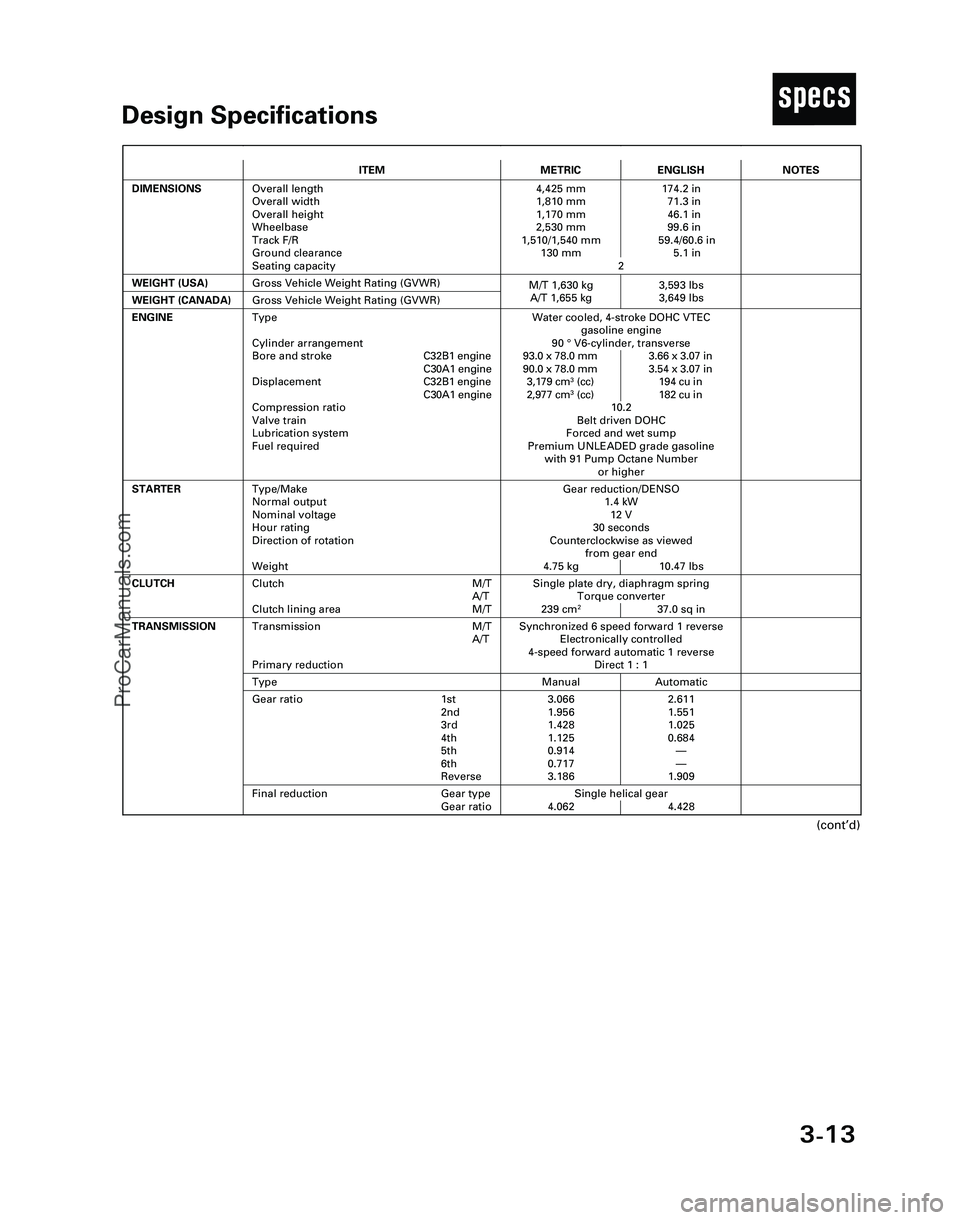
TDesign Specifications
(cont’d)
ITEMMETRICENGLISH
DIMENSIONSOverall length
Overall width
Overall height
Wheelbase
Track F/R
Ground clearance
Seating capacity4,425 mm 174.2 in
1,810 mm 71.3 in
1,170 mm 46.1 in
2,530 mm 99.6 in
1,510/1,540 mm 59.4/60.6 in
130 mm 5.1 in
2
WEIGHT (USA)
Single plate dry, diaphragm spring
Torque converter
239 cm
237.0 sq in
CLUTCHClutch M/T
A/T
Clutch lining area M/T
Gross Vehicle Weight Rating (GVWR)
NOTES
Gear reduction/DENSO
1.4 kW
12 V
30 seconds
Counterclockwise as viewed
from gear end
4.75 kg 10.47 lbs
ENGINEWater cooled, 4-stroke DOHC VTEC
gasoline engine
90 °V6-cylinder, transverse
93.0 x 78.0 mm 3.66 x 3.07 in
90.0 x 78.0 mm 3.54 x 3.07 in
3,179 cm
3(cc) 194 cu in
2,977 cm3(cc) 182 cu in
10.2
Belt driven DOHC
Forced and wet sump
Premium UNLEADED grade gasoline
with 91 Pump Octane Number
or higher
STARTERType/Make
Normal output
Nominal voltage
Hour rating
Direction of rotation
Weight
WEIGHT (CANADA)Gross Vehicle Weight Rating (GVWR)
Synchronized 6 speed forward 1 reverse
Electronically controlled
4-speed forward automatic 1 reverse
Direct 1 : 1Transmission M/T
A/T
Primary reduction
Manual AutomaticType
3.066 2.611
1.956 1.551
1.428 1.025
1.125 0.684
0.914—
0.717—
3.186 1.909Gear ratio 1st
2nd
3rd
4th
5th
6th
Reverse
Single helical gear
4.062 4.428
TRANSMISSION
Final reduction Gear type
Gear ratio
Type
Cylinder arrangement
Bore and strokeC32B1 engine
C30A1 engine
DisplacementC32B1 engine
C30A1 engine
Compression ratio
Valve train
Lubrication system
Fuel required
M/T 1,630 kg 3,593 lbs
A/T 1,655 kg 3,649 lbs
*04-NSX (61SW004)SEC03(01-16) 9/22/04 1:49 PM Page 3-13
ProCarManuals.com
Page 459 of 1503
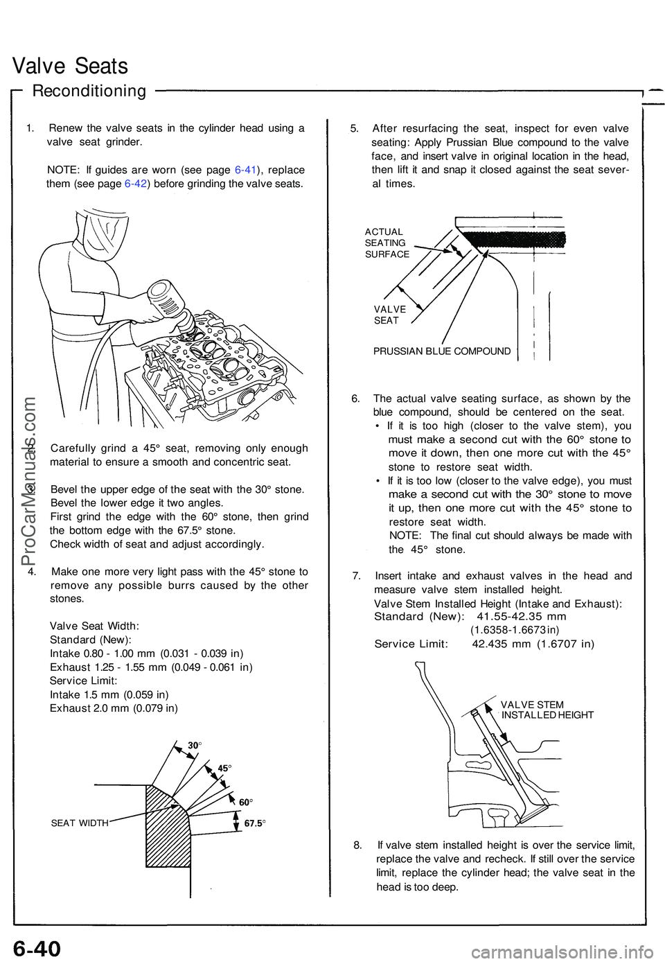
Valve Seat s
Reconditionin g
1. Rene w th e valv e seat s i n th e cylinde r hea d usin g a
valv e sea t grinder .
NOTE : I f guide s ar e wor n (se e pag e 6-41 ), replac e
the m (se e pag e 6-42 ) befor e grindin g th e valv e seats .
2 . Carefull y grin d a 45 ° seat , removin g onl y enoug h
materia l t o ensur e a smoot h an d concentri c seat .
3 . Beve l th e uppe r edg e o f th e sea t wit h th e 30 ° stone .
Beve l th e lowe r edg e i t tw o angles .
Firs t grin d th e edg e wit h th e 60 ° stone , the n grin d
th e botto m edg e wit h th e 67.5 ° stone .
Chec k widt h o f sea t an d adjus t accordingly .
4 . Mak e on e mor e ver y ligh t pas s wit h th e 45 ° ston e t o
remov e an y possibl e burr s cause d b y th e othe r
stones .
Valv e Sea t Width :
Standar d (New) :
Intak e 0.8 0 - 1.0 0 m m (0.03 1 - 0.03 9 in )
Exhaus t 1.2 5 - 1.5 5 m m (0.04 9 - 0.06 1 in )
Servic e Limit :
Intak e 1. 5 m m (0.05 9 in )
Exhaus t 2. 0 m m (0.07 9 in )
SEA T WIDT H
5. Afte r resurfacin g th e seat , inspec t fo r eve n valv e
seating : Appl y Prussia n Blu e compoun d t o th e valv e
face , an d inser t valv e i n origina l locatio n i n th e head ,
the n lif t i t an d sna p i t close d agains t th e sea t sever -
a l times .
ACTUA L
SEATIN G
SURFAC E
VALVESEAT
PRUSSIA N BLU E COMPOUN D
6. Th e actua l valv e seatin g surface , a s show n b y th e
blu e compound , shoul d b e centere d o n th e seat .
• I f i t i s to o hig h (close r t o th e valv e stem) , yo u
mus t mak e a secon d cu t wit h th e 60 ° ston e t o
mov e it down , the n on e mor e cu t wit h th e 45 °
ston e t o restor e sea t width .
• I f i t i s to o lo w (close r t o th e valv e edge) , yo u mus t
make a secon d cu t wit h th e 30 ° ston e t o mov e
it up , the n on e mor e cu t wit h th e 45 ° ston e t o
restor e sea t width .
NOTE : Th e fina l cu t shoul d alway s b e mad e wit h
th e 45 ° stone .
7 . Inser t intak e an d exhaus t valve s i n th e hea d an d
measur e valv e ste m installe d height .
Valv e Ste m Installe d Heigh t (Intak e an d Exhaust) :
Standard (New) : 41.55-42.3 5 m m
(1.6358-1.667 3 in )
Servic e Limit : 42.43 5 m m (1.670 7 in )
VALV E STE M
INSTALLE D HEIGH T
8. I f valv e ste m installe d heigh t i s ove r th e servic e limit ,
replac e th e valv e an d recheck . I f stil l ove r th e servic e
limit , replac e th e cylinde r head ; th e valv e sea t i n th e
hea d is to o deep .
ProCarManuals.com
Page 667 of 1503
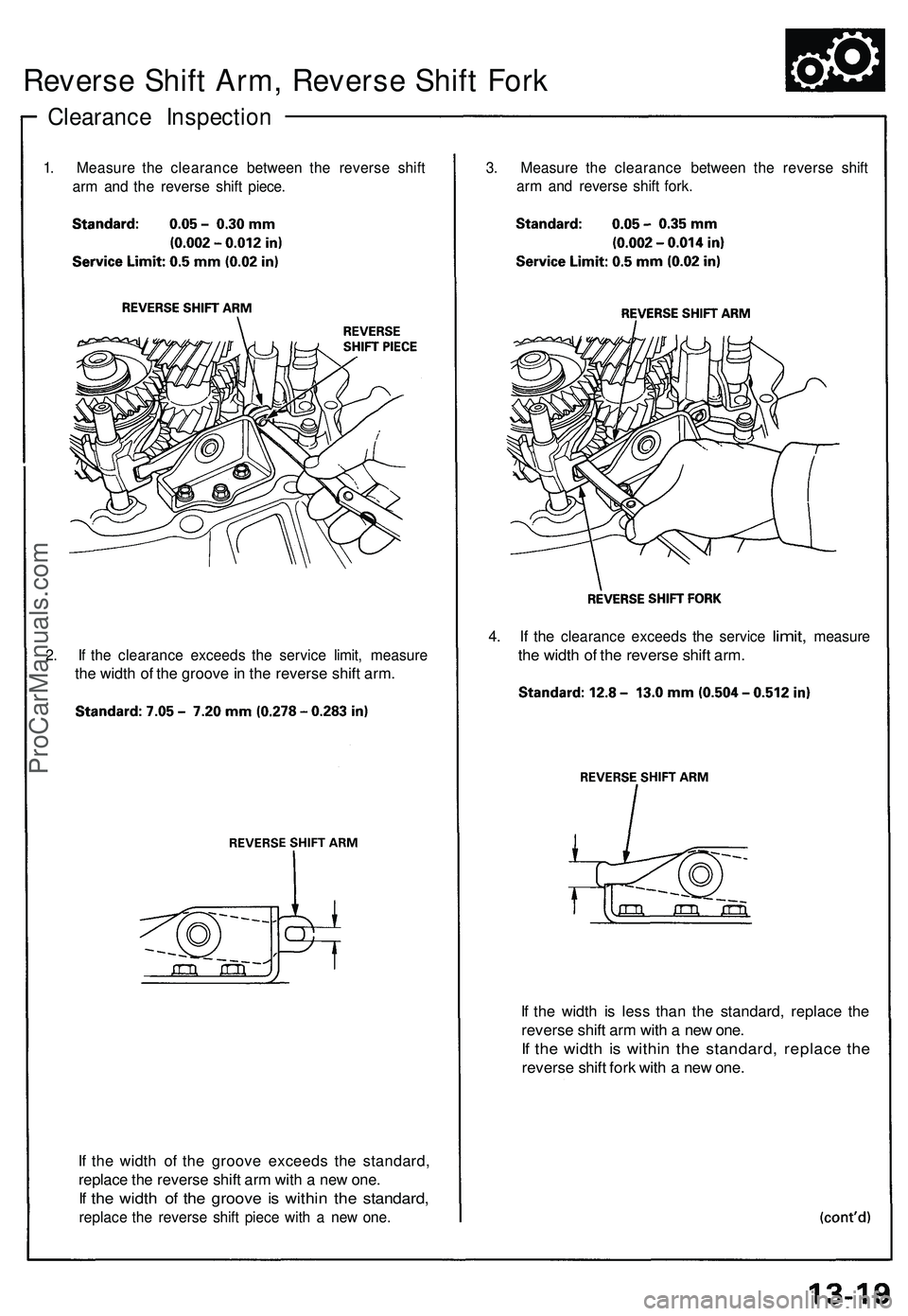
Reverse Shift Arm, Reverse Shift Fork
Clearance Inspection
1. Measure the clearance between the reverse shift
arm and the reverse shift piece.
2. If the clearance exceeds the service limit, measure
the width of the groove in the reverse shift arm.
If the width of the groove exceeds the standard,
replace the reverse shift arm with a new one.
If the width of the groove is within the standard,
replace the reverse shift piece with a new one.
If the width is less than the standard, replace the
reverse shift arm with a new one.
If the width is within the standard, replace the
reverse shift fork with a new one.
3. Measure the clearance between the reverse shift
arm and reverse shift fork.
4. If the
clearance exceeds
the
service
limit,
measure
the width of the reverse shift arm.ProCarManuals.com
Page 679 of 1503
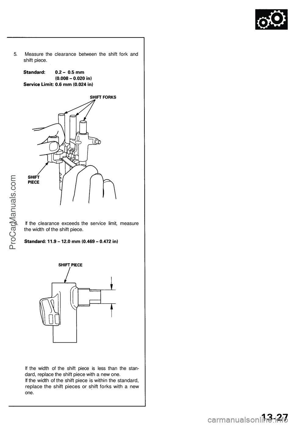
5. Measure the clearance between the shift fork and
shift piece.
6. If the clearance exceeds the service limit, measure
the width of the shift piece.
If the width of the shift piece is less than the stan-
dard, replace the shift piece with a new one.
If the width of the shift piece is within the standard,
replace the shift pieces or shift forks with a new
one.ProCarManuals.com
Page 680 of 1503
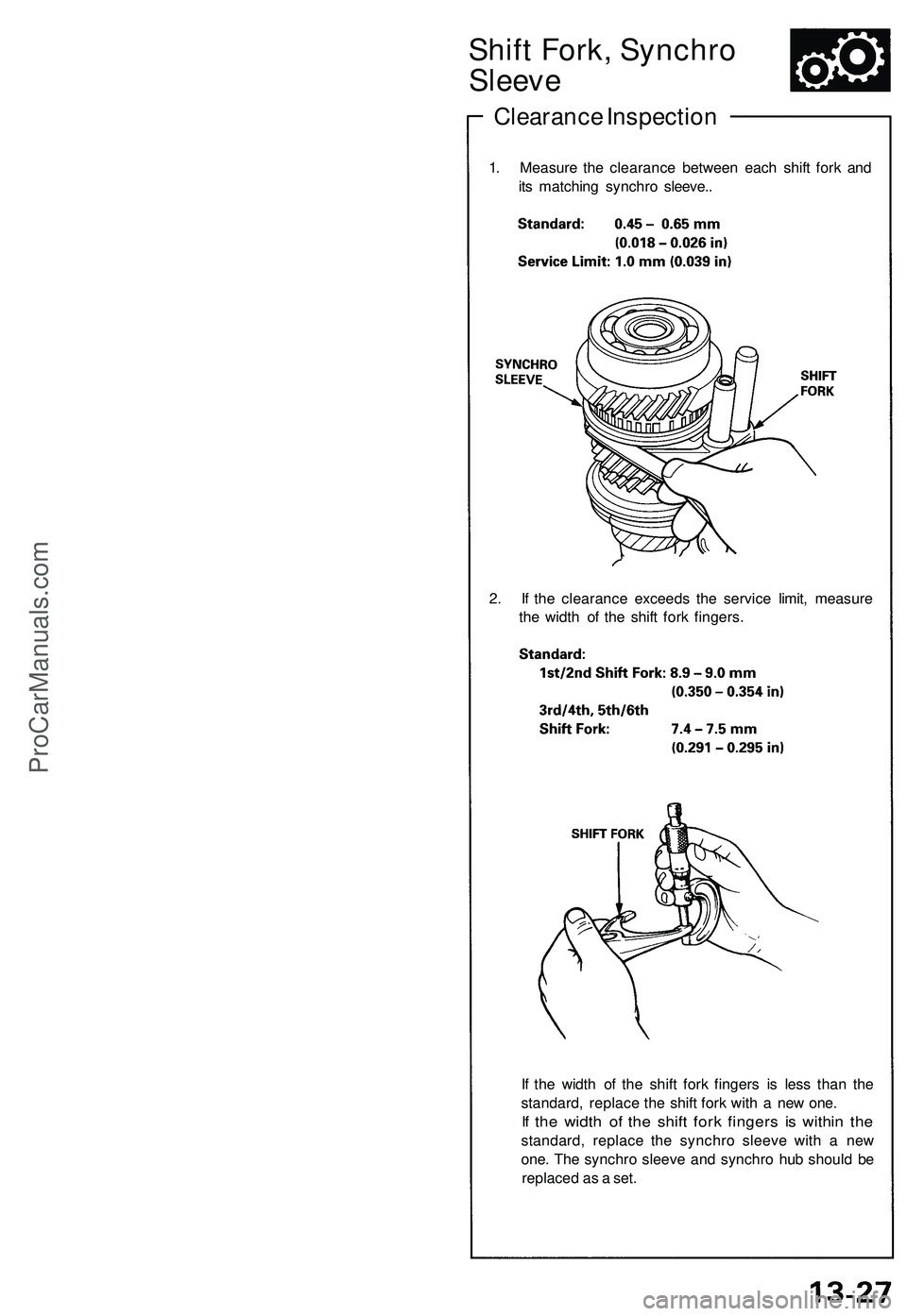
Shift Fork, Synchro
Sleeve
Clearance Inspection
1. Measure the clearance between each shift fork and
its matching synchro sleeve..
2. If the clearance exceeds the service limit, measure
the width of the shift fork fingers.
If the width of the shift fork fingers is less than the
standard, replace the shift fork with a new one.
If the width of the shift fork fingers is within the
standard, replace the synchro sleeve with a new
one. The synchro sleeve and synchro hub should be
replaced as a set.ProCarManuals.com
Page 903 of 1503
System Description
Function and Operation (cont'd)
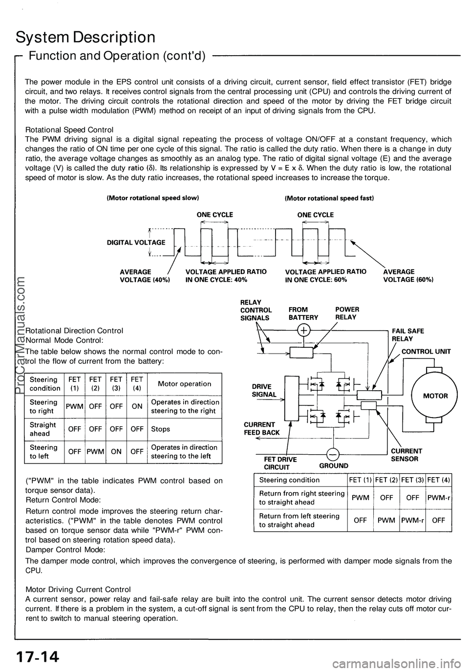
The power module in the EPS control unit consists of a driving circuit, current sensor, field effect transistor (FET) bridge
circuit, and two relays. It receives control signals from the central processing unit (CPU) and controls the driving current of
the motor. The driving circuit controls the rotational direction and speed of the motor by driving the FET bridge circuit
with a pulse width modulation (PWM) method on receipt of an input of driving signals from the CPU.
Rotational Speed Control
The PWM driving signal is a digital signal repeating the process of voltage ON/OFF at a constant frequency, which
changes the ratio of ON time per one cycle of this signal. The ratio is called the duty ratio. When there is a change in duty
ratio, the average voltage changes as smoothly as an analog type. The ratio of digital signal voltage (E) and the average
voltage (V) is called the duty Its relationship is expressed by When the duty ratio is low, the rotational
speed of motor is slow. As the duty ratio increases, the rotational speed increases to increase the torque.
Rotational Direction Control
Normal Mode Control:
The table below shows the normal control mode to con-
trol the flow of current from the battery:
("PWM" in the table indicates PWM control based on
torque sensor data).
Return Control Mode:
Return control mode improves the steering return char-
acteristics. ("PWM" in the table denotes PWM control
based on torque sensor data while "PWM-r" PWM con-
trol based on steering rotation speed data).
Damper Control Mode:
The damper mode control, which improves the convergence of steering, is performed with damper mode signals from the
CPU.
Motor Driving Current Control
A current sensor, power relay and fail-safe relay are built into the control unit. The current sensor detects motor driving
current. If there is a problem in the system, a cut-off signal is sent from the CPU to relay, then the relay cuts off motor cur-
rent to switch to manual steering operation.ProCarManuals.com
Page 938 of 1503
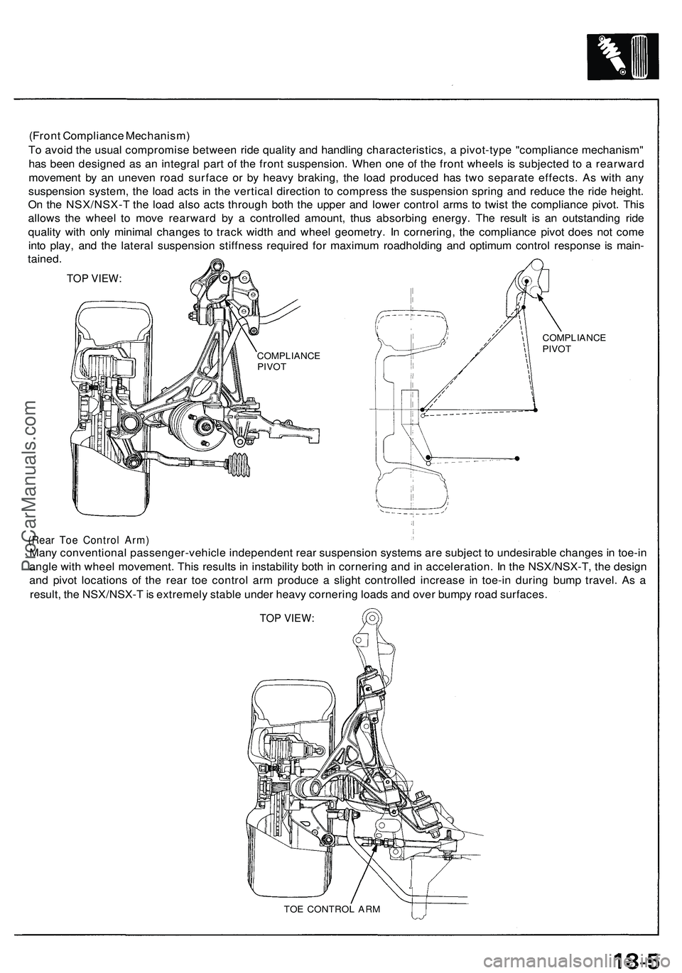
(Front Compliance Mechanism)
To avoid the usual compromise between ride quality and handling characteristics, a pivot-type "compliance mechanism"
has been designed as an integral part of the front suspension. When one of the front wheels is subjected to a rearward
movement by an uneven road surface or by heavy braking, the load produced has two separate effects. As with any
suspension system, the load acts in the vertical direction to compress the suspension spring and reduce the ride height.
On the NSX/NSX-T the load also acts through both the upper and lower control arms to twist the compliance pivot. This
allows the wheel to move rearward by a controlled amount, thus absorbing energy. The result is an outstanding ride
quality with only minimal changes to track width and wheel geometry. In cornering, the compliance pivot does not come
into play, and the lateral suspension stiffness required for maximum roadholding and optimum control response is main-
tained.
TOP VIEW:
(Rear Toe Control Arm)
Many conventional passenger-vehicle independent rear suspension systems are subject to undesirable changes in toe-in
angle with wheel movement. This results in instability both in cornering and in acceleration. In the NSX/NSX-T, the design
and pivot locations of the rear toe control arm produce a slight controlled increase in toe-in during bump travel. As a
result, the NSX/NSX-T is extremely stable under heavy cornering loads and over bumpy road surfaces.
TOP VIEW:
TOE CONTROL ARM
COMPLIANCE
PIVOT
COMPLIANCE
PIVOTProCarManuals.com
Page 1143 of 1503
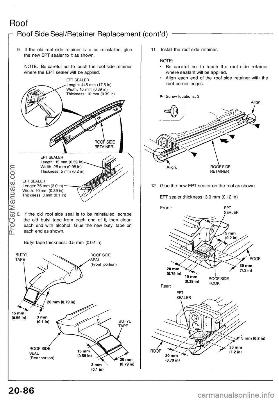
Roof
Roof Sid e Seal/Retaine r Replacemen t (cont'd )
9. I f th e ol d roo f sid e retaine r i s t o b e reinstalled , glu e
th e ne w EP T seale r t o it a s shown .
NOTE : B e carefu l no t t o touc h th e roo f sid e retaine r
wher e th e EP T seale r wil l b e applied .
EPT SEALE RLength: 44 5 m m (17. 5 in )
Width : 1 0 m m (0.3 9 in )
Thickness : 1 0 m m (0.3 9 in )
EP T SEALE RLength: 1 5 m m (0.5 9 in )Width : 2 5 m m (0.9 8 in )Thickness : 5 m m (0. 2 in )
EP T SEALE RLength: 7 5 m m (3. 0 in )Width : 1 0 m m (0.3 9 in )Thickness : 3 m m (0. 1 in )
10. I f th e ol d roo f sid e sea l i s t o b e reinstalled , scrap e
th e ol d buty l tap e fro m eac h en d of it, the n clea n
eac h en d wit h alcohol . Glu e th e ne w buty l tap e o n
eac h en d a s shown .
Buty l tap e thickness : 0. 5 m m (0.0 2 in )
BUTY LTAPEROO F SID ESEA L(Fron t portion )
BUTYLTAPE
ROO F SID ESEA L(Rea r portion )
11. Instal l th e roo f sid e retainer .
NOTE :
• B e carefu l no t t o touc h th e roo f sid e retaine r
where sealan t wil l b e applied .
• Alig n eac h en d o f th e roo f sid e retaine r wit h th e
roo f corne r edges .
Screw locations , 3
Align .
Align.ROOF SID ERETAINE R
12. Glu e th e ne w EP T seale r o n th e roo f a s shown .
EPT seale r thickness : 3. 0 m m (0.1 2 in )
Front :
ROOF
Rear :
ROOF
ROOF SID ERETAINE R
EPTSEALE R
ROOF SID EHOO K
EPTSEALE R
ProCarManuals.com