jump start ACURA NSX 1997 Service Repair Manual
[x] Cancel search | Manufacturer: ACURA, Model Year: 1997, Model line: NSX, Model: ACURA NSX 1997Pages: 1503, PDF Size: 57.08 MB
Page 587 of 1503
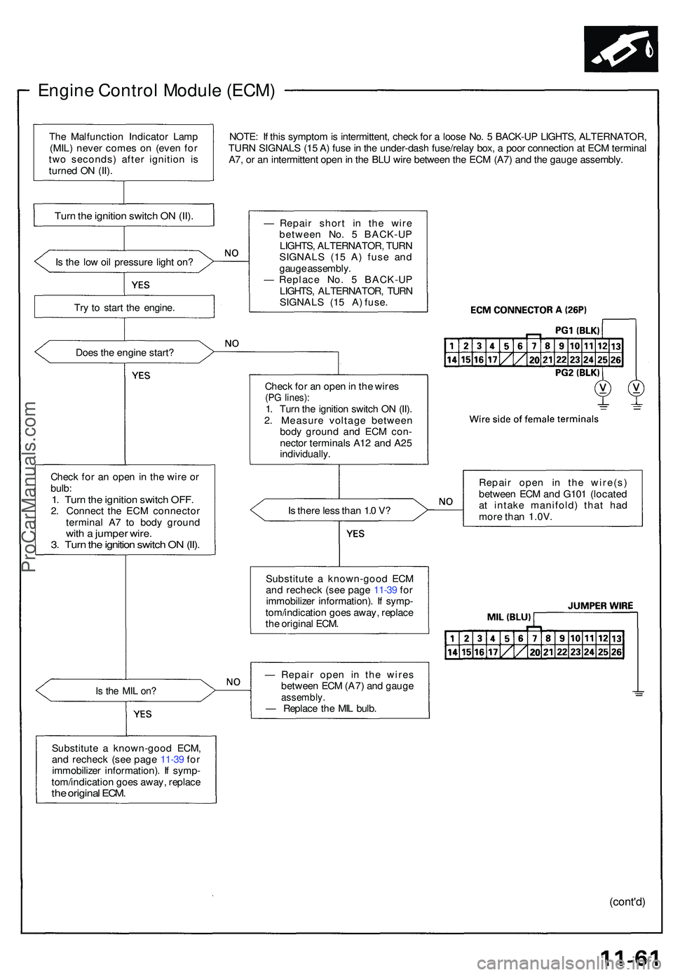
Engine Contro l Modul e (ECM )
NOTE: I f thi s sympto m is intermittent , chec k fo r a loos e No . 5 BACK-U P LIGHTS , ALTERNATOR ,
TUR N SIGNAL S (1 5 A ) fus e in th e under-das h fuse/rela y box , a poo r connectio n a t EC M termina l
A7 , o r a n intermitten t ope n in th e BL U wir e betwee n th e EC M (A7 ) an d th e gaug e assembly .
I s th e lo w oi l pressur e ligh t on ?
Tr y t o star t th e engine .
Doe s th e engin e start ?
Chec k fo r a n ope n in th e wir e o r
bulb :
1. Tur n th e ignitio n switc h OFF .2. Connec t th e EC M connecto r
termina l A 7 t o bod y groun d
with a jumpe r wire .3. Tur n th e ignitio n switc h O N (II) .
Is th e MI L on ?
Substitut e a known-goo d ECM ,
an d rechec k (se e pag e 11-3 9 fo r
immobilize r information) . I f symp -
tom/indicatio n goe s away , replac e
the origina l ECM .
— Repai r shor t i n the wir e
betwee n No . 5 BACK-U P
LIGHTS , ALTERNATOR , TUR N
SIGNAL S (1 5 A ) fus e an d
gaug e assembly .
— Replac e No . 5 BACK-U P
LIGHTS , ALTERNATOR , TUR N
SIGNALS (15 A) fuse.
Chec k fo r a n ope n in th e wire s
(PG lines) :1. Tur n th e ignitio n switc h O N (II) .
2 . Measur e voltag e betwee n
bod y groun d an d EC M con -
necto r terminal s A1 2 an d A2 5
individually .
I s ther e les s tha n 1. 0 V ?
Substitut e a known-goo d EC M
an d rechec k (se e pag e 11-3 9 fo r
immobilize r information) . I f symp -
tom/indicatio n goe s away , replac e
th e origina l ECM . Repai
r ope n i n th e wire(s )
betwee n EC M an d G10 1 (locate d
a t intak e manifold ) tha t ha d
mor e tha n 1.0V .
— Repai r ope n i n th e wire s
betwee n EC M (A7 ) an d gaug e
assembly .— Replac e th e MI L bulb .
(cont'd )
Turn th e ignitio n switc h O N (II) .
The Malfunctio n Indicato r Lam p
(MIL ) neve r come s o n (eve n fo r
tw o seconds ) afte r ignitio n i s
turne d O N (II) .
ProCarManuals.com
Page 660 of 1503
Transmission Assembl y
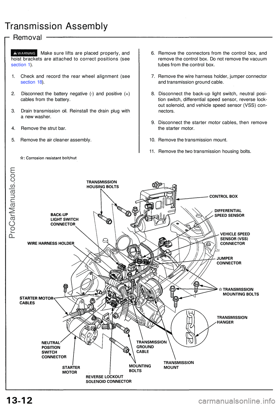
Removal
Make sur e lift s ar e place d properly , an d
hois t bracket s ar e attache d t o correc t position s (se e
sectio n 1 ).
1 . Chec k an d recor d th e rea r whee l alignmen t (se e
sectio n 18 ).
2 . Disconnec t th e batter y negativ e (- ) an d positiv e (+ )
cable s fro m th e battery .
3 . Drai n transmissio n oil . Reinstal l th e drai n plu g wit h
a ne w washer .
4 . Remov e th e stru t bar .
5 . Remov e th e ai r cleane r assembly . 6
. Remov e th e connector s fro m th e contro l box , an d
remov e th e contro l box . D o no t remov e th e vacuu m
tube s fro m th e contro l box .
7 . Remov e th e wir e harnes s holder , jumpe r connecto r
an d transmissio n groun d cable .
8 . Disconnec t th e back-u p ligh t switch , neutra l posi -
tio n switch , differentia l spee d sensor , revers e lock -
ou t solenoid , an d vehicl e spee d senso r (VSS ) con -
nectors .
9. Disconnec t th e starte r moto r cables , the n remov e
th e starte r motor .
10 . Remov e th e transmissio n mount .
11 . Remov e th e tw o transmissio n housin g bolts .
ProCarManuals.com
Page 710 of 1503
Transmission Assembl y
Installatio n (cont'd )
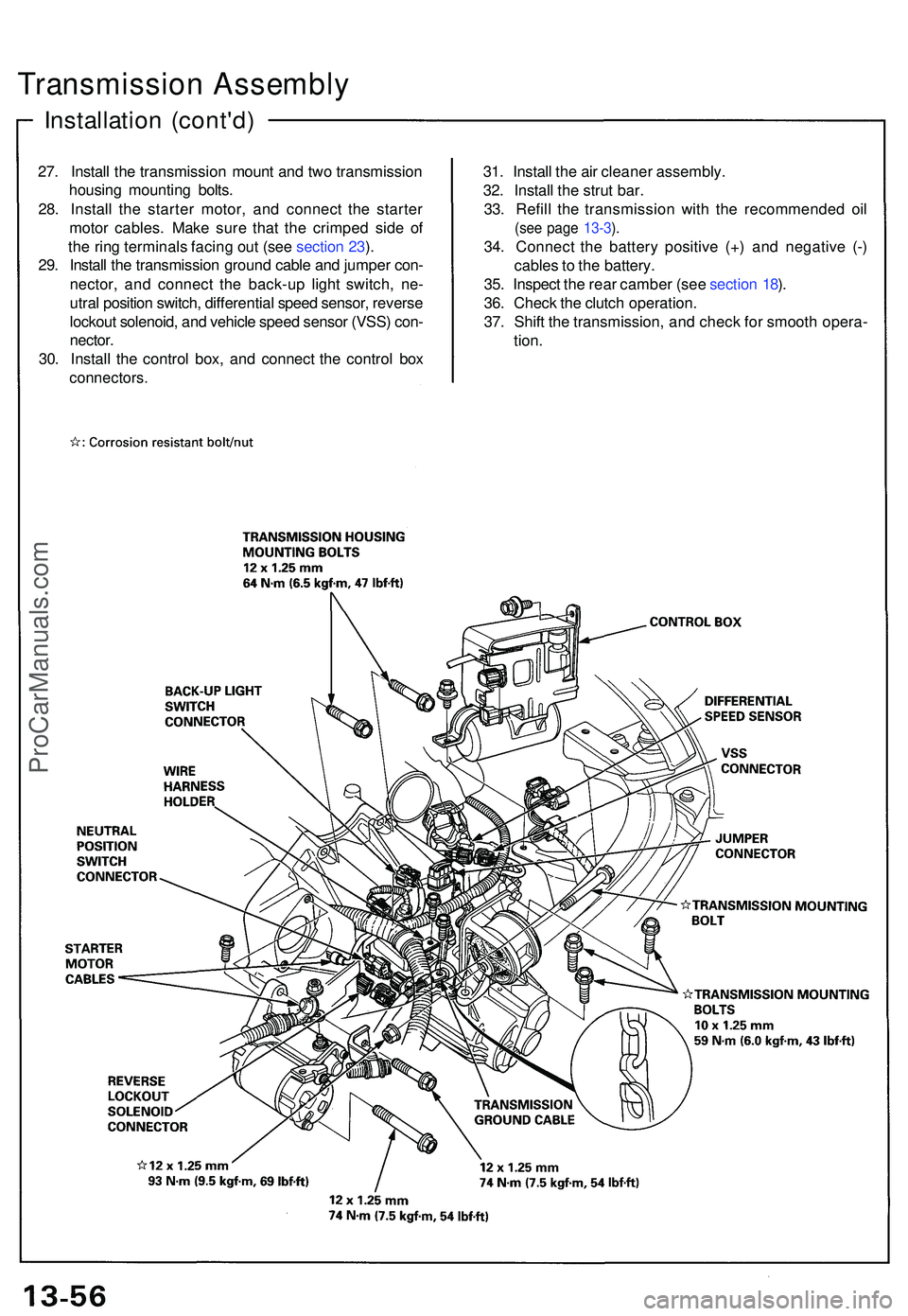
27. Instal l th e transmissio n moun t an d tw o transmissio n
housin g mountin g bolts .
28 . Instal l th e starte r motor , an d connec t th e starte r
moto r cables . Mak e sur e tha t th e crimpe d sid e o f
th e rin g terminal s facin g ou t (se e sectio n 23 ).
29 . Instal l th e transmissio n groun d cabl e an d jumpe r con -
nector , an d connec t th e back-u p ligh t switch , ne -
utra l positio n switch , differentia l spee d sensor , revers e
lockou t solenoid , an d vehicl e spee d senso r (VSS ) con -
nector .
30 . Instal l th e contro l box , an d connec t th e contro l bo x
connectors .
31. Instal l th e ai r cleane r assembly .
32 . Instal l th e stru t bar .
33 . Refil l th e transmissio n wit h th e recommende d oi l
(se e pag e 13-3 ).
34 . Connec t th e batter y positiv e (+ ) an d negativ e (- )
cable s to th e battery .
35 . Inspec t th e rea r cambe r (se e sectio n 18 ).
36 . Chec k th e clutc h operation .
37 . Shif t th e transmission, and chec k fo r smoot h opera -
tion .
ProCarManuals.com
Page 1035 of 1503
Solenoid Flushin g
Modulator/Solenoi d Uni t
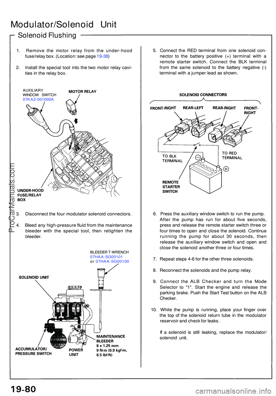
1. Remov e th e moto r rela y fro m th e under-hoo d
fuse/rela y box . (Location : se e pag e 19-38 )
2 . Instal l th e specia l too l int o th e tw o moto r rela y cavi -
tie s in th e rela y box .
AUXILIAR YWINDOW SWITC H07KAZ-001000 A
5. Connec t th e RE D termina l fro m on e solenoi d con -
necto r t o th e batter y positiv e (+ ) termina l wit h a
remot e starte r switch . Connec t th e BL K termina l
fro m th e sam e solenoi d t o th e batter y negativ e (- )
termina l wit h a jumpe r lea d a s shown .
3 . Disconnec t th e fou r modulato r solenoi d connectors .
4 . Blee d an y high-pressur e flui d fro m th e maintenanc e
bleede r wit h th e specia l tool , the n retighte n th e
bleeder .
BLEEDE R T-WRENC H07HAA-SG0010 1or 07HAA-SG0010 0
6. Pres s th e auxiliar y windo w switc h t o ru n th e pump .
Afte r th e pum p ha s ru n fo r abou t fiv e seconds ,
pres s an d releas e th e remot e starte r switc h thre e o r
fou r time s t o ope n an d clos e th e solenoid . Continu e
runnin g th e pum p fo r abou t 3 0 seconds , the n
releas e th e auxiliar y windo w switc h an d ope n an d
clos e th e solenoi d anothe r thre e o r fou r times .
7 . Repea t step s 4- 6 fo r th e othe r thre e solenoids .
8 . Reconnec t th e solenoid s an d th e pum p relay .
9 . Connec t th e AL B Checke r an d tur n th e Mod e
Selecto r t o "1" . Star t th e engin e an d releas e th e
parkin g brake . Pus h th e Star t Tes t butto n o n th e AL B
Checker .
10. Whil e th e pum p i s running , plac e you r finge r ove r
th e to p o f th e solenoi d retur n tub e i n th e modulato r
reservoi r an d chec k fo r leaks .
I f a solenoi d i s stil l leaking , replac e th e modulator /
solenoi d unit .
ProCarManuals.com
Page 1250 of 1503
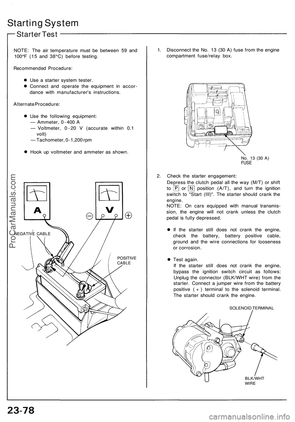
Starting Syste m
Starte r Tes t
NOTE : Th e ai r temperatur e mus t b e betwee n 5 9 an d
100° F (1 5 an d 38°C ) befor e testing .
Recommende d Procedure :
Use a starte r syste m tester .
Connec t an d operat e th e equipmen t i n accor -
danc e wit h manufacturer' s instructions .
Alternat e Procedure :
Us e th e followin g equipment :
— Ammeter , 0 - 40 0 A
— Voltmeter , 0 - 2 0 V (accurat e withi n 0. 1
volt )
— Tachometer , 0 -1,20 0 rp m
Hoo k u p voltmete r an d ammete r a s shown .
NEGATIV E CABL E
POSITIV ECABLE
1. Disconnec t th e No . 1 3 (3 0 A ) fus e fro m th e engin e
compartmen t fuse/rela y box .
No. 1 3 (3 0 A )FUS E
2. Chec k th e starte r engagement :
Depres s th e clutc h peda l al l th e wa y (M/T ) o r shif t
to o r positio n (A/T) , an d tur n th e ignitio n
switc h t o "Star t (III)" . Th e starte r shoul d cran k th e
engine .
NOTE: O n car s equippe d wit h manua l transmis -
sion , th e engin e wil l no t cran k unles s th e clutc h
peda l i s full y depressed .
I f th e starte r stil l doe s no t cran k th e engine ,
chec k th e battery , batter y positiv e cable ,
ground and th e wir e connection s fo r loosenes s
o r corrosion .
Tes t again .
If th e starte r stil l doe s no t cran k th e engine ,
bypas s th e ignitio n switc h circui t a s follows :
Unplu g th e connecto r (BLK/WH T wire ) fro m th e
starter . Connec t a jumpe r wir e fro m th e batter y
positiv e ( + ) termina l t o th e solenoi d terminal .
Th e starte r shoul d cran k th e engine .
SOLENOI D TERMINA L
BLK/WHTWIRE
ProCarManuals.com
Page 1272 of 1503
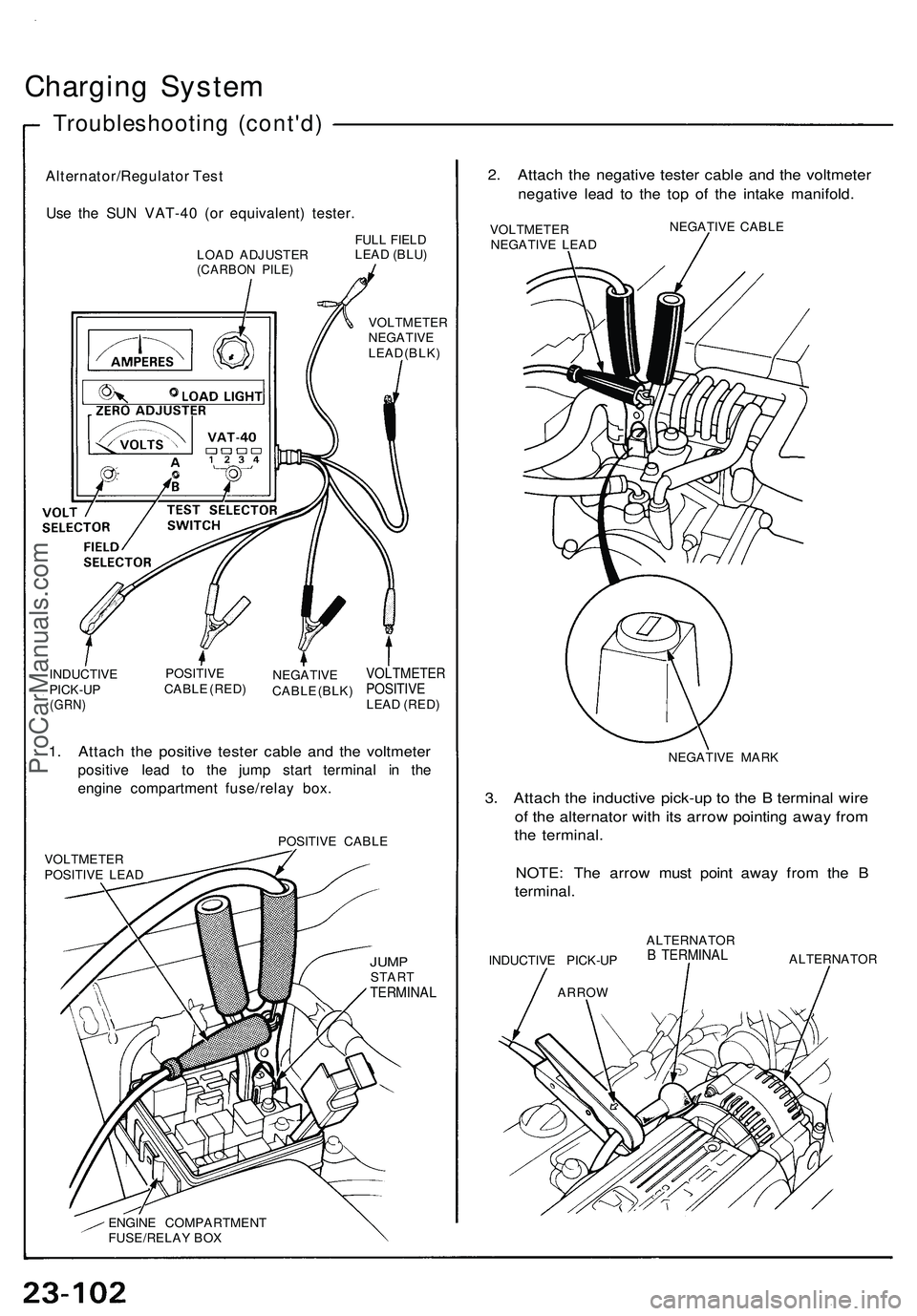
Charging System
Troubleshooting (cont'd)
Alternator/Regulator Test
Use the SUN VAT-40 (or equivalent) tester.
LOAD ADJUSTER
(CARBON PILE)
FULL FIELD
LEAD (BLU)
VOLTMETER
NEGATIVE
LEAD (BLK)
INDUCTIVE
PICK-UP
(GRN)
POSITIVE
CABLE (RED)
NEGATIVE
CABLE (BLK)
VOLTMETER
POSITIVE
LEAD (RED)
1. Attach the positive tester cable and the voltmeter
positive lead to the jump start terminal in the
engine compartment fuse/relay box.
POSITIVE CABLE
VOLTMETER
POSITIVE LEAD
JUMP
START
TERMINAL
ENGINE COMPARTMENT
FUSE/RELAY BOX
2. Attach the negative tester cable and the voltmeter
negative lead to the top of the intake manifold.
VOLTMETER
NEGATIVE LEAD
NEGATIVE CABLE
NEGATIVE MARK
3. Attach the inductive pick-up to the B terminal wire
of the alternator with its arrow pointing away from
the terminal.
NOTE: The arrow must point away from the B
terminal.
INDUCTIVE PICK-UP
ARROW
ALTERNATOR
B TERMINAL
ALTERNATORProCarManuals.com
Page 1296 of 1503
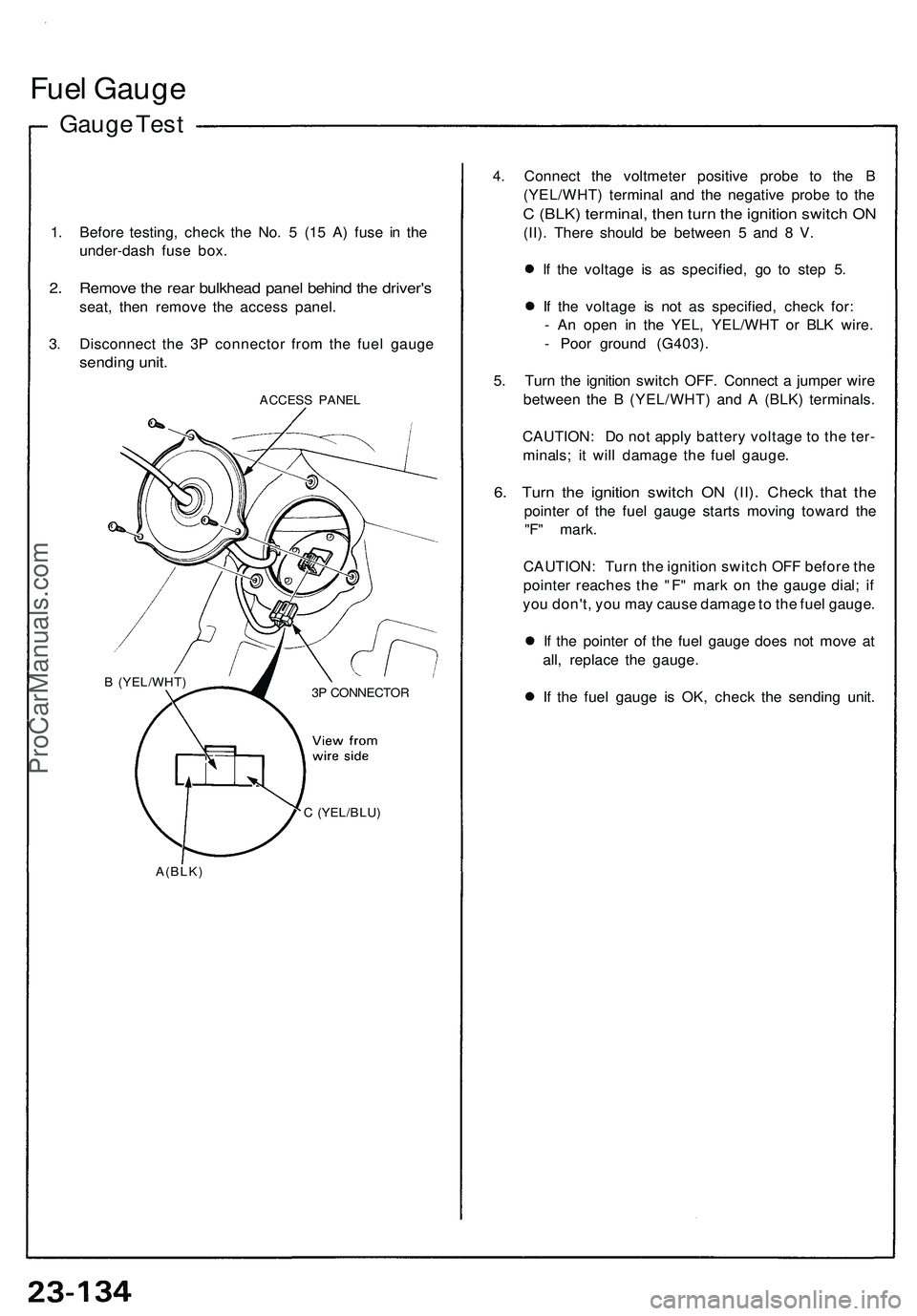
Fuel Gaug e
Gauge Tes t
1. Befor e testing , chec k th e No . 5 (15 A ) fus e i n th e
under-das h fus e box .
2. Remov e th e rea r bulkhea d pane l behin d th e driver' s
seat, the n remov e th e acces s panel .
3 . Disconnec t th e 3 P connecto r fro m th e fue l gaug e
sendin g unit .
ACCES S PANE L
C (YEL/BLU )
A(BLK )
4. Connec t th e voltmete r positiv e prob e t o th e B
(YEL/WHT ) termina l an d th e negativ e prob e t o th e
C (BLK ) terminal , the n tur n th e ignitio n switc h O N
(II) . Ther e shoul d b e betwee n 5 an d 8 V .
I f th e voltag e i s a s specified , g o t o ste p 5 .
I f th e voltag e i s no t a s specified , chec k for :
- A n ope n i n th e YEL , YEL/WH T o r BL K wire .
- Poo r groun d (G403) .
5 . Tur n th e ignitio n switc h OFF . Connec t a jumpe r wir e
betwee n th e B (YEL/WHT ) an d A (BLK ) terminals .
CAUTION : D o no t appl y batter y voltag e t o th e ter -
minals ; i t wil l damag e th e fue l gauge .
6. Tur n th e ignitio n switc h O N (II) . Chec k tha t th e
pointe r o f th e fue l gaug e start s movin g towar d th e
"F " mark .
CAUTION : Tur n th e ignitio n switc h OF F befor e th e
pointe r reache s th e "F" mar k o n th e gaug e dial ; i f
yo u don't , yo u ma y caus e damag e to th e fue l gauge .
I f th e pointe r o f th e fue l gaug e doe s no t mov e a t
all , replac e th e gauge .
I f th e fue l gaug e i s OK , chec k th e sendin g unit .
B (YEL/WHT )
3P CONNECTO R
ProCarManuals.com
Page 1298 of 1503
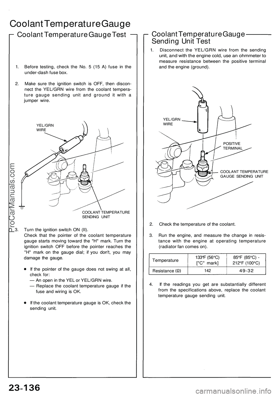
Coolant Temperatur e Gaug e
Coolan t Temperatur e Gaug e Tes t
1. Befor e testing , chec k th e No . 5 (1 5 A ) fus e i n th e
under-das h fus e box .
2 . Mak e sur e th e ignitio n switc h i s OFF , the n discon -
nec t th e YEL/GR N wir e fro m th e coolan t tempera -
tur e gaug e sendin g uni t an d groun d i t wit h a
jumpe r wire .
YEL/GR NWIRE
COOLAN T TEMPERATUR ESENDING UNI T
3. Tur n th e ignitio n switc h O N (II) .
Chec k tha t th e pointe r o f th e coolan t temperatur e
gaug e start s movin g towar d th e "H " mark . Tur n th e
ignitio n switc h OF F befor e th e pointe r reache s th e
"H " mar k o n th e gaug e dial ; i f yo u don't , yo u ma y
damag e th e gauge .
I f th e pointe r o f th e gaug e doe s no t swin g a t all ,
chec k for :
— An ope n in th e YE L o r YEL/GR N wire .
— Replac e th e coolan t temperatur e gaug e i f th e
fus e an d wirin g i s OK .
I f th e coolan t temperatur e gaug e is OK , chec k th e
sendin g unit .
Coolan t Temperatur e Gaug e ———
Sendin g Uni t Tes t
1. Disconnec t th e YEL/GR N wir e fro m th e sendin g
unit, an d wit h th e engin e cold , us e a n ohmmete r t o
measur e resistanc e betwee n th e positiv e termina l
an d th e engin e (ground) .
COOLAN T TEMPERATUR EGAUGE SENDIN G UNI T
2. Chec k th e temperatur e o f th e coolant .
3 . Ru n th e engine , an d measur e th e chang e i n resis -
tanc e wit h th e engin e a t operatin g temperatur e
(radiato r fa n come s on) .
Temperatur e
Resistance
133°F (56°C )
["C " mark ]
142
85° F (85°C ) -
212° F (100°C )
49-32
4. I f th e reading s yo u ge t ar e substantiall y differen t
fro m th e specification s above , replac e th e coolan t
temperatur e gaug e sendin g unit .
YEL/GR NWIRE
POSITIV ETERMINA L
ProCarManuals.com
Page 1299 of 1503
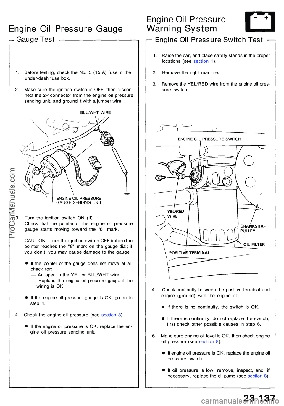
Engine Oi l Pressur e Gaug e
Gauge Tes t
1. Befor e testing , chec k th e No . 5 (15 A ) fus e i n th e
under-das h fus e box .
2 . Mak e sur e th e ignitio n switc h i s OFF , the n discon -
nec t th e 2 P connecto r fro m th e engin e oi l pressur e
sendin g unit , an d groun d i t wit h a jumpe r wire .
BLU/WH T WIR E
ENGIN E OI L PRESSUR E
GAUGE SENDIN G UNI T
3. Tur n th e ignitio n switc h O N (II) .
Chec k tha t th e pointe r o f th e engin e oi l pressur e
gauge start s movin g towar d th e "8 " mark .
CAUTION : Tur n th e ignitio n switc h OF F befor e th e
pointe r reache s th e "8 " mar k o n th e gaug e dial ; i f
yo u don't , yo u ma y cause damag e t o th e gauge .
I f th e pointe r o f th e gaug e doe s no t mov e a t all ,
chec k for :
— A n ope n i n th e YE L o r BLU/WH T wire .
— Replac e th e engin e oi l pressur e gaug e i f th e
wirin g i s OK .
I f th e engin e oi l pressur e gaug e i s OK , g o o n t o
ste p 4 .
4 . Chec k th e engine-oi l pressur e (se e sectio n 8 ).
I f th e engin e oi l pressur e i s OK , replac e th e en -
gin e oi l pressur e sendin g unit .
Engin e Oi l Pressur e
Warning Syste m
Engine Oi l Pressur e Switc h Tes t
1. Rais e th e car , an d plac e safet y stand s i n th e prope r
location s (se e sectio n 1 ).
2 . Remov e th e righ t rea r tire .
3 . Remov e th e YEL/RE D wir e fro m th e engin e oi l pres -
sur e switch .
ENGINE OI L PRESSUR E SWITC H
4. Chec k continuit y betwee n th e positiv e termina l an d
engin e (ground ) wit h th e engin e off .
I f ther e i s n o continuity , th e switc h i s OK .
If ther e is continuity , d o no t replac e th e switch ;
first chec k othe r possible causes i n ste p 6 .
6. Mak e sur e engin e oi l leve l i s OK , the n chec k engin e
oil pressur e (se e sectio n 8 ).
If engin e oi l pressur e is OK , replac e th e engin e oi l
pressur e switch .
If oi l pressur e i s low , remove , inspect , and , i f
necessary , replac e th e oi l pum p (se e sectio n 8 ).
ProCarManuals.com