engine oil ACURA NSX 1997 Service Repair Manual
[x] Cancel search | Manufacturer: ACURA, Model Year: 1997, Model line: NSX, Model: ACURA NSX 1997Pages: 1503, PDF Size: 57.08 MB
Page 31 of 1503
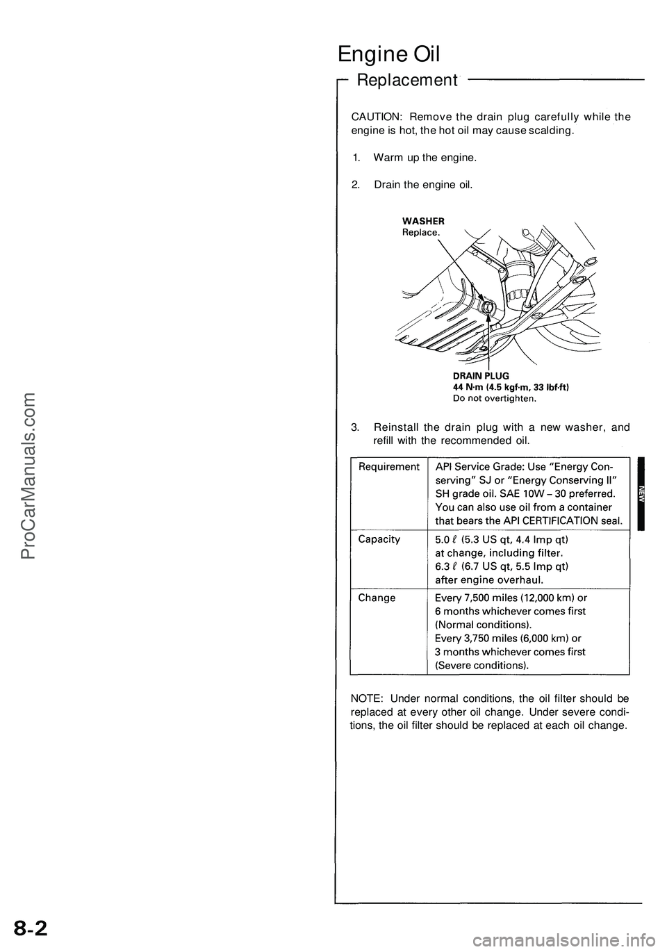
Engine Oi l
Replacemen t
CAUTION: Remov e th e drai n plu g carefull y whil e th e
engin e is hot , th e ho t oi l ma y caus e scalding .
1 . War m u p th e engine .
2 . Drai n th e engin e oil .
3 . Reinstal l th e drai n plu g wit h a ne w washer , an d
refil l wit h th e recommende d oil .
NOTE : Unde r norma l conditions , th e oi l filte r shoul d b e
replace d a t ever y othe r oi l change . Unde r sever e condi -
tions , th e oi l filte r shoul d b e replace d a t eac h oi l change .
ProCarManuals.com
Page 32 of 1503
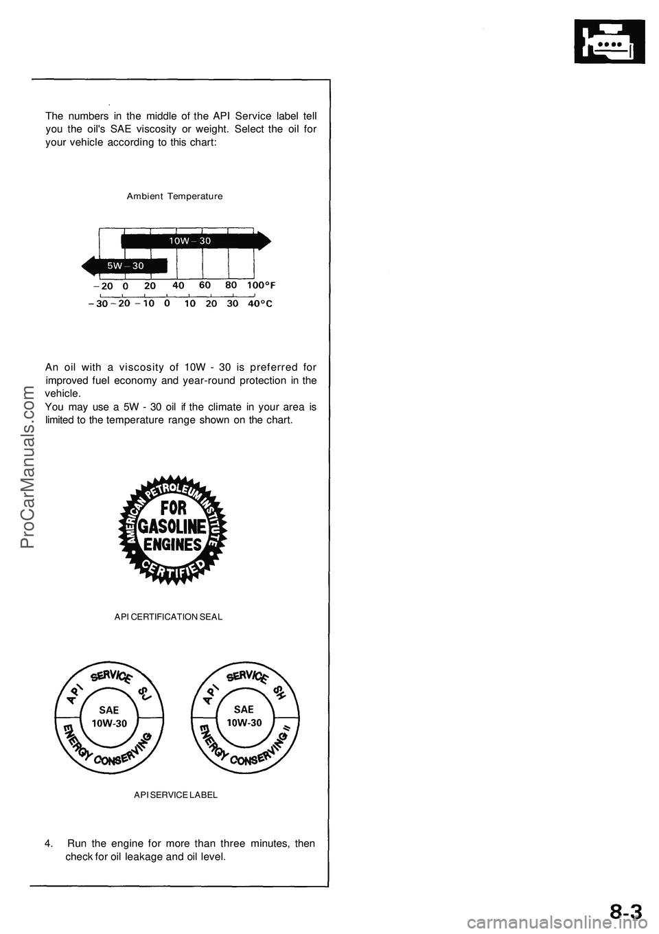
The numbers in the middle of the API Service label tell
you the oil's SAE viscosity or weight. Select the oil for
your vehicle according to this chart:
Ambient Temperature
An oil with a viscosity of 10W - 30 is preferred for
improved fuel economy and year-round protection in the
vehicle.
You may use a 5W - 30 oil if the climate in your area is
limited to the temperature range shown on the chart.
API CERTIFICATION SEAL
API SERVICE LABEL
4. Run the engine for more than three minutes, then
check for oil leakage and oil level.ProCarManuals.com
Page 348 of 1503
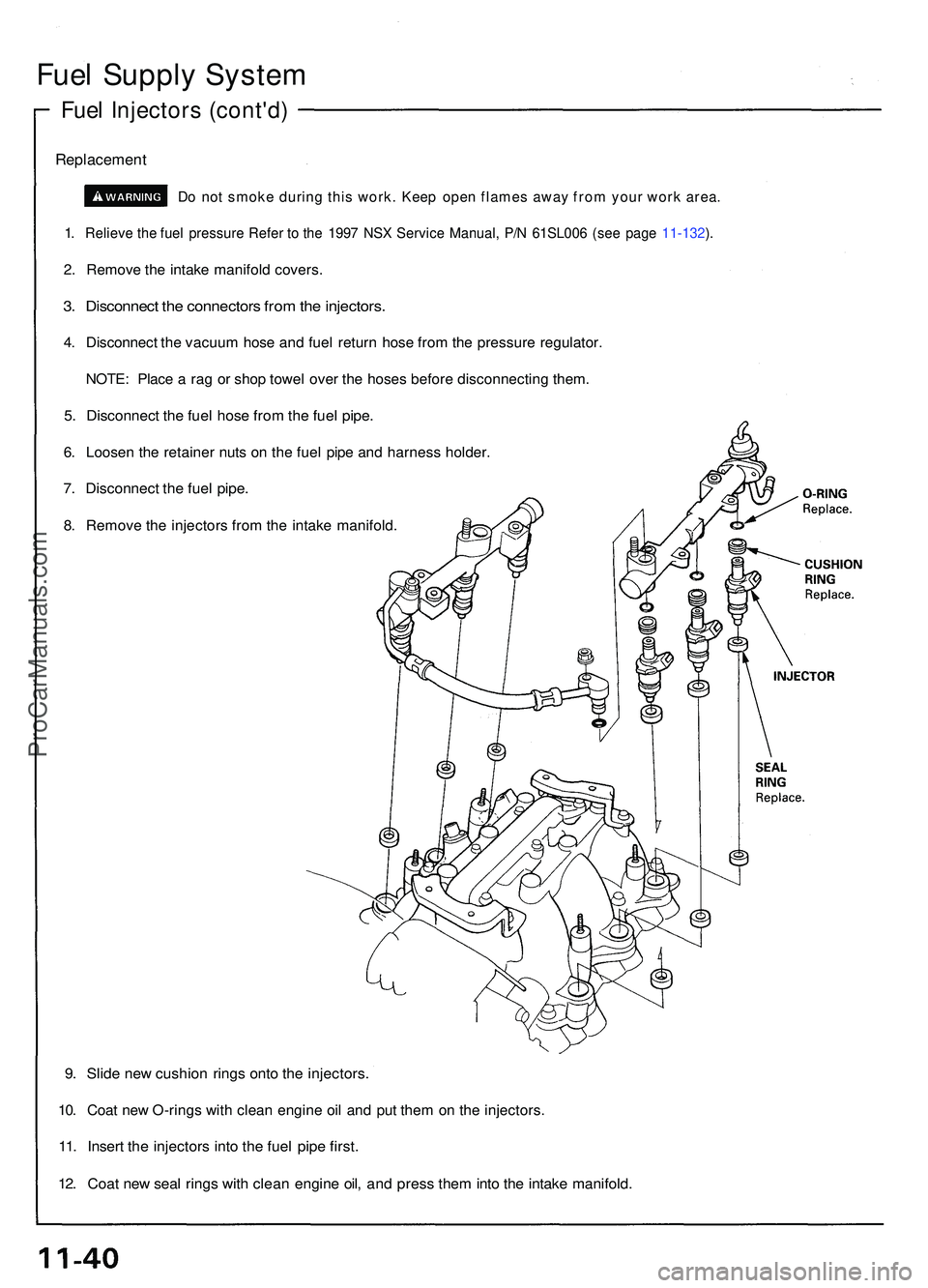
Fuel Suppl y Syste m
Fuel Injector s (cont'd )
Replacemen t
Do no t smok e durin g thi s work . Kee p ope n flame s awa y fro m you r wor k area .
1. Reliev e th e fue l pressur e Refe r t o th e 199 7 NS X Servic e Manual , P/ N 61SL00 6 (se e pag e 11-132 ).
2 . Remov e th e intak e manifol d covers .
3. Disconnec t th e connector s fro m th e injectors .
4. Disconnec t th e vacuu m hos e an d fue l retur n hos e fro m th e pressur e regulator .
NOTE: Plac e a ra g o r sho p towe l ove r th e hose s befor e disconnectin g them .
5. Disconnec t th e fue l hos e fro m th e fue l pipe .
6. Loose n th e retaine r nut s o n th e fue l pip e an d harnes s holder .
7. Disconnec t th e fue l pipe .
8. Remov e th e injector s fro m th e intak e manifold .
9. Slid e ne w cushio n ring s ont o th e injectors .
10. Coa t ne w O-ring s wit h clea n engin e oi l an d pu t the m o n th e injectors .
11. Inser t th e injector s int o th e fue l pip e first .
12. Coa t ne w sea l ring s wit h clea n engine oil, an d pres s the m int o th e intak e manifold .
ProCarManuals.com
Page 349 of 1503
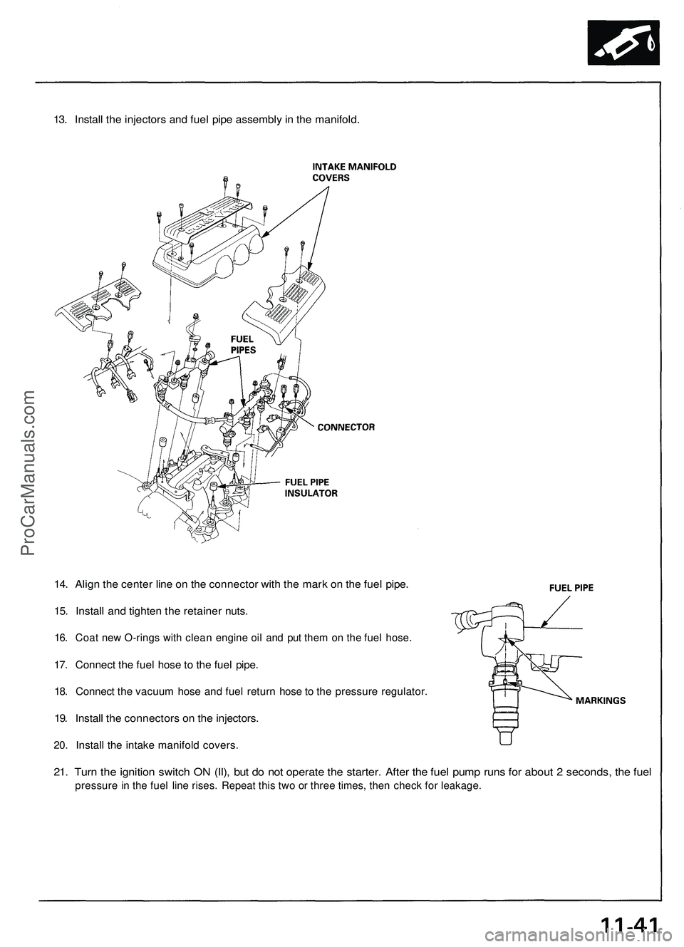
13. Install the injectors and fuel pipe assembly in the manifold.
14. Align the center line on the connector with the mark on the fuel pipe.
15. Install and tighten the retainer nuts.
16. Coat new O-rings with clean engine oil and put them on the fuel hose.
17. Connect the fuel hose to the fuel pipe.
18. Connect the vacuum hose and fuel return hose to the pressure regulator.
19. Install the connectors on the injectors.
20. Install the intake manifold covers.
21. Turn the ignition switch ON (II), but do not operate the starter. After the fuel pump runs for about 2 seconds, the fuel
pressure in the fuel line rises. Repeat this two or three times, then check for leakage.ProCarManuals.com
Page 367 of 1503
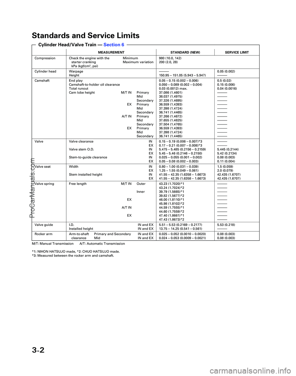
3-2
Standards and Service Limits
MEASUREMENTSTANDARD (NEW)SERVICE LIMIT
CompressionCheck the engine with the Minimumstarter cranking Maximum variation
kPa (kgf/cm
2, psi)
980 (10.0, 142)
200 (2.0, 28)
Cylinder headWarpage
Height—150.95 – 151.05 (5.943 – 5.947)0.05 (0.002)—
CamshaftEnd play
Camshaft-to-holder oil clearance
Total runout
Cam lobe height M/T IN Primary Mid
Secondary
EX Primary Mid
Secondary
A/T IN Primary Mid
Secondary
EX Primary Mid
Secondary0.05 – 0.15 (0.002 – 0.006)
0.050 – 0.089 (0.002 – 0.004)
0.03 (0.0012) max.
37.086 (1.4601)
38.037 (1.4975)
37.326 (1.4695)
36.559 (1.4393)
37.398 (1.4724)
36.741 (1.4465)
37.266 (1.4672)
37.655 (1.4825)
37.504 (1.4765)
36.559 (1.4393)
37.398 (1.4724)
36.741 (1.4465)0.5 (0.02)
0.15 (0.006)
0.04 (0.0016)
—
—
—
—
—
—
—
—
—
—
—
—
ValveValve clearance IN EX
Valve stem O.D. IN EX
Stem-to-guide clearance IN EX0.15 – 0.19 (0.006 – 0.007)*3
0.17 – 0.21 (0.007 – 0.008)*3
5.475 – 5.485 (0.2156 – 0.2159)
5.45 – 5.46 (0.2146 – 0.2150)
0.025 – 0.055 (0.001 – 0.002)
0.05 – 0.08 (0.002 – 0.003)—
—
5.445 (0.2144)
5.42 (0.2134)
0.08 (0.003)
0.11 (0.004)
Valve seatWidth INEX
Stem installed height IN EX0.80 – 1.00 (0.031 – 0.039)
1.25 – 1.55 (0.049 – 0.061)
41.55 – 42.35 (1.6358 – 1.6673)
41.55 – 42.35 (1.6358 – 1.6673)1.5 (0.059)
2.0 (0.079)
42.435 (1.6707)
42.435 (1.6707)
Valve springFree length M/T IN Outer
Inner
EX
A/T IN EX43.23 (1.7020)*1
43.24 (1.7024)*2
39.79 (1.5665)*1
39.82 (1.5677)*2
46.00 (1.8110)*1
45.98 (1.8102)*2
44.59 (1.7555)*1
44.60 (1.7559)*2
47.40 (1.8661)*1
47.43 (1.8673)*2—
—
—
—
—
—
—
—
—
—
Valve guideI.D. IN and EX
Installed height IN and EX5.51 – 5.53 (0.2169 – 0.2177)
13.75 – 14.25 (0.541 – 0.561)5.53 (0.218)—
Rocker armArm-to-shaft Primary and Secondary IN and EXclearance Mid IN and EX0.025 – 0.052 (0.0010 – 0.0020)
0.024 – 0.053 (0.0009 – 0.0021)0.08 (0.003)
0.08 (0.003)
M/T: Manual Transmission A/T: Automatic Transmission
*1: NIHON HATSUJO made, *2: CHUO HATSUJO made.
*3: Measured between the rocker arm and camshaft.
Cylinder Head/Valve Train — Section 6
*04-NSX (61SW004)SEC03(01-16) 9/22/04 1:48 PM Page 3-2
ProCarManuals.com
Page 371 of 1503
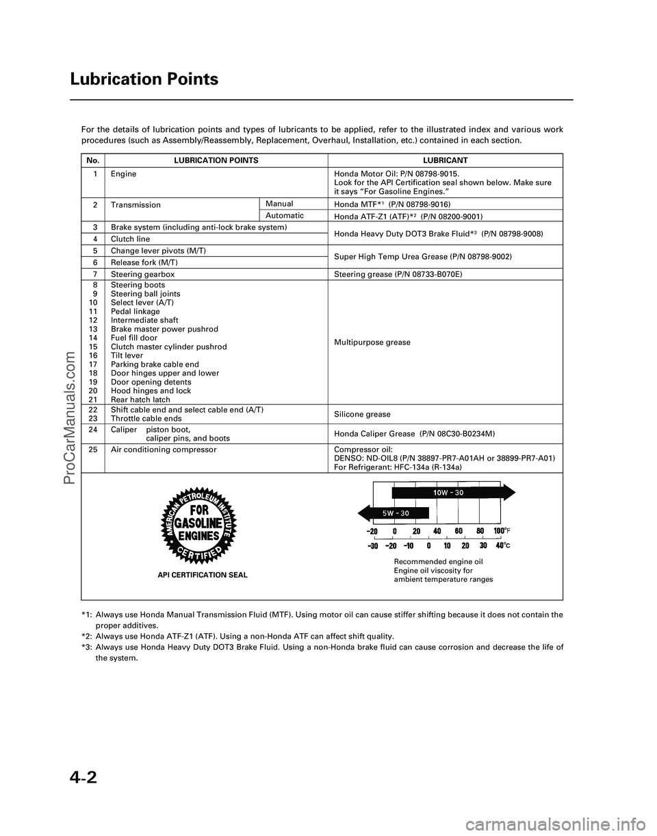
4-2
For the details of lubrication points and types of lubricants to be appl\
ied, refer to the illustrated index and various work
procedures (such as Assembly/Reassembly, Replacement, Overhaul, Install\
ation, etc.) contained in each section.
*1: Always use Honda Manual Transmission Fluid (MTF). Using motor oil can \
cause stiffer shifting because it does not contain theproper additives.
*2: Always use Honda ATF-Z1 (ATF). Using a non-Honda ATF can affect shift \
quality.
*3: Always use Honda Heavy Duty DOT3 Brake Fluid. Using a non-Honda brake fl\
uid can cause corrosion and decrease the life of the system.
Lubrication Points
No.LUBRICATION POINTSLUBRICANT
1Honda Motor Oil: P/N 08798-9015.
Look for the API Certification seal shown below. Make sure
it says “For Gasoline Engines.”
2TransmissionHonda MTF*1(P/N 08798-9016)
3Brake system (including anti-lock brake system)Honda Heavy Duty DOT3 Brake Fluid*3(P/N 08798-9008)4Clutch line
5Change lever pivots (M/T)Super High Temp Urea Grease (P/N 08798-9002)6Release fork (M/T)
8
9
10
11
12
13
14
15
16
17
18
19
20
21Steering boots
Steering ball joints
Select lever (A/T)
Pedal linkage
Intermediate shaft
Brake master power pushrod
Fuel fill door
Clutch master cylinder pushrod
Tilt lever
Parking brake cable end
Door hinges upper and lower
Door opening detents
Hood hinges and lock
Rear hatch latch
Multipurpose grease
24
22
23
Caliper piston boot, caliper pins, and boots
Shift cable end and select cable end (A/T)
Throttle cable ends
Honda Caliper Grease (P/N 08C30-B0234M)
Silicone grease
25Air conditioning compressorCompressor oil:
DENSO: ND-OIL8 (P/N 38897-PR7-A01AH or 38899-PR7-A01)
For Refrigerant: HFC-134a (R-134a)
Manual
Honda ATF-Z1 (ATF)*2(P/N 08200-9001)Automatic
7Steering gearboxSteering grease (P/N 08733-B070E)
Engine
API CERTIFICATION SEAL
Recommended engine oil
Engine oil viscosity for
ambient temperature ranges
*05-NSX (61SW004)SEC04(01-10) 9/22/04 1:49 PM Page 4-2
ProCarManuals.com
Page 374 of 1503
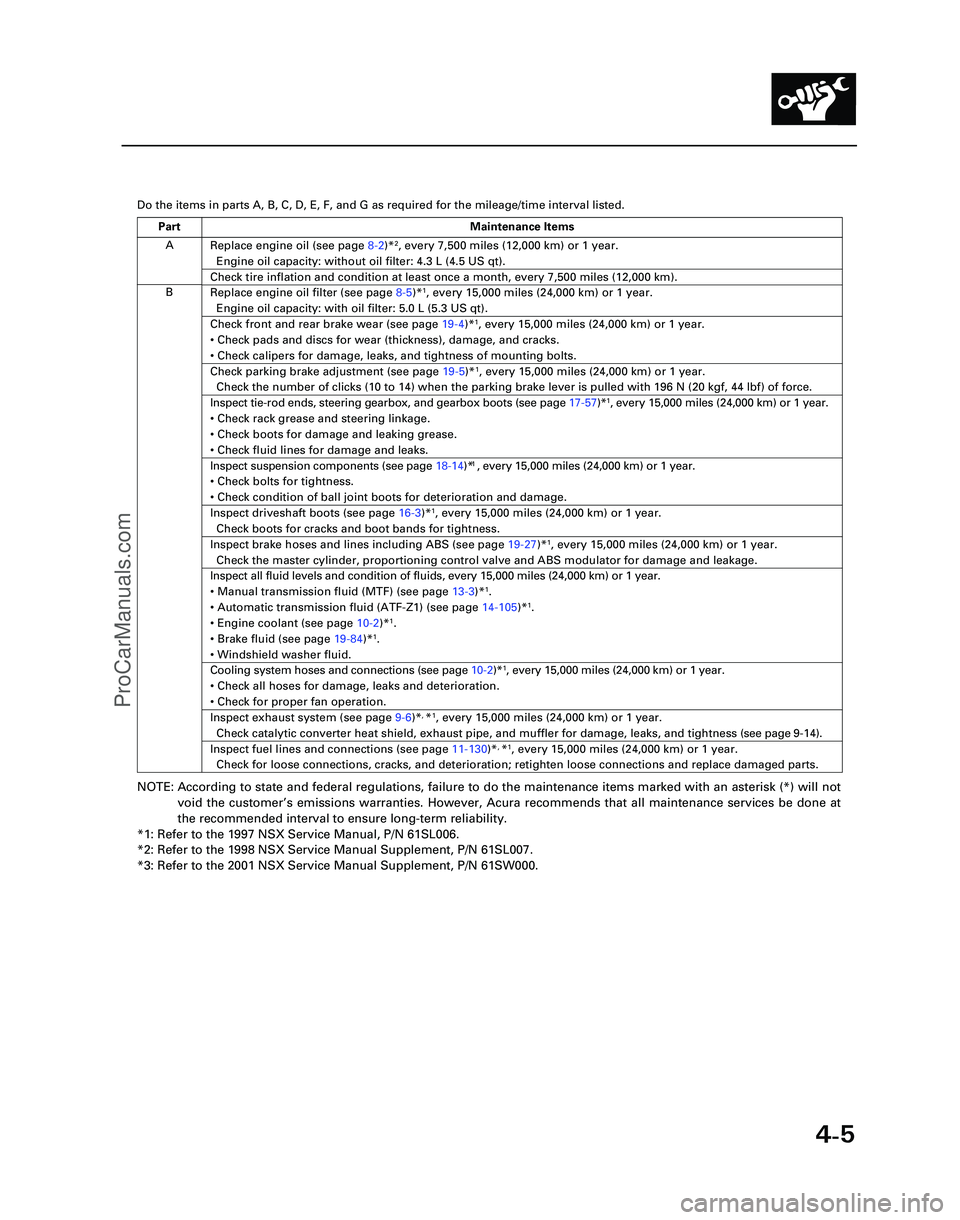
4-5
Y
Do the items in parts A, B, C, D, E, F, and G as required for the mileag\
e/time interval listed.
NOTE: According to state and federal regulations, failure to do the maintenanc\
e items marked with an asterisk (*) will not
void the customer ’s emissions warranties. However, Acura recommends that all maintenance s\
ervices be done at
the recommended interval to ensure long-term reliability.
*1: Refer to the 1997 NSX Service Manual, P/N 61SL006.
*2: Refer to the 1998 NSX Service Manual Supplement, P/N 61SL007.
*3: Refer to the 2001 NSX Service Manual Supplement, P/N 61SW000.
A
B Replace engine oil (see page
8-2)*
2, every 7,500 miles (12,000 km) or 1 year.
Engine oil capacity: without oil filter: 4.3 L (4.5 US qt).
Check tire inflation and condition at least once a month, every 7,500 mi\
les (12,000 km).
Replace engine oil filter (see page 8-5)*1, every 15,000 miles (24,000 km) or 1 year.
Engine oil capacity: with oil filter: 5.0 L (5.3 US qt).
Check front and rear brake wear (see page 19-4)*1, every 15,000 miles (24,000 km) or 1 year.
• Check pads and discs for wear (thickness), damage, and cracks.
• Check calipers for damage, leaks, and tightness of mounting bolts.
Check parking brake adjustment (see page 19-5)*1, every 15,000 miles (24,000 km) or 1 year.
Check the number of clicks (10 to 14) when the parking brake lever is pulled with 196 N (20 kgf,\
44 lbf) of force.
Inspect tie-rod ends, steering gearbox, and gearbox boots (see page 17-57)*1, every 15,000 miles (24,000 km) or 1 year.
• Check rack grease and steering linkage.
• Check boots for damage and leaking grease.
• Check fluid lines for damage and leaks.1
• Check bolts for tightness.
• Check condition of ball joint boots for deterioration and damage.
Inspect driveshaft boots (see page 16-3)*1, every 15,000 miles (24,000 km) or 1 year.
Check boots for cracks and boot bands for tightness.
Inspect brake hoses and lines including ABS (see page 19-27)*1, every 15,000 miles (24,000 km) or 1 year.
Check the master cylinder, proportioning control valve and ABS modulator\
for damage and leakage.
Inspect all fluid levels and condition of fluids, every 15,000 miles (2\
4,000 km) or 1 year.
• Manual transmission fluid (MTF) (see page 13-3)*
1.
• Automatic transmission fluid (ATF-Z1) (see page 14-105)*1.
• Engine coolant (see page 10-2)*1.
• Brake fluid (see page 19-84)*1.
• Windshield washer fluid.
Cooling system hoses and connections (see page 10-2)*1, every 15,000 miles (24,000 km) or 1 year.
• Check all hoses for damage, leaks and deterioration.
• Check for proper fan operation.
Inspect exhaust system (see page 9-6)*, *1, every 15,000 miles (24,000 km) or 1 year.
Check catalytic converter heat shield, exhaust pipe, and muffler for dam\
age, leaks, and tightness ( see page 9-14 ).
Inspect fuel lines and connections (see page 11-130)*, *1, every 15,000 miles (24,000 km) or 1 year.
Check for loose connections, cracks, and deterioration; retighten loose \
connections and replace damaged parts.
Part Maintenance Items
*05-NSX (61SW004)SEC04(01-10) 9/22/04 1:49 PM Page 4-5
Inspect suspension components (see page 18-14)* , every 15,000 miles (24,000 km) or 1 year.
ProCarManuals.com
Page 417 of 1503
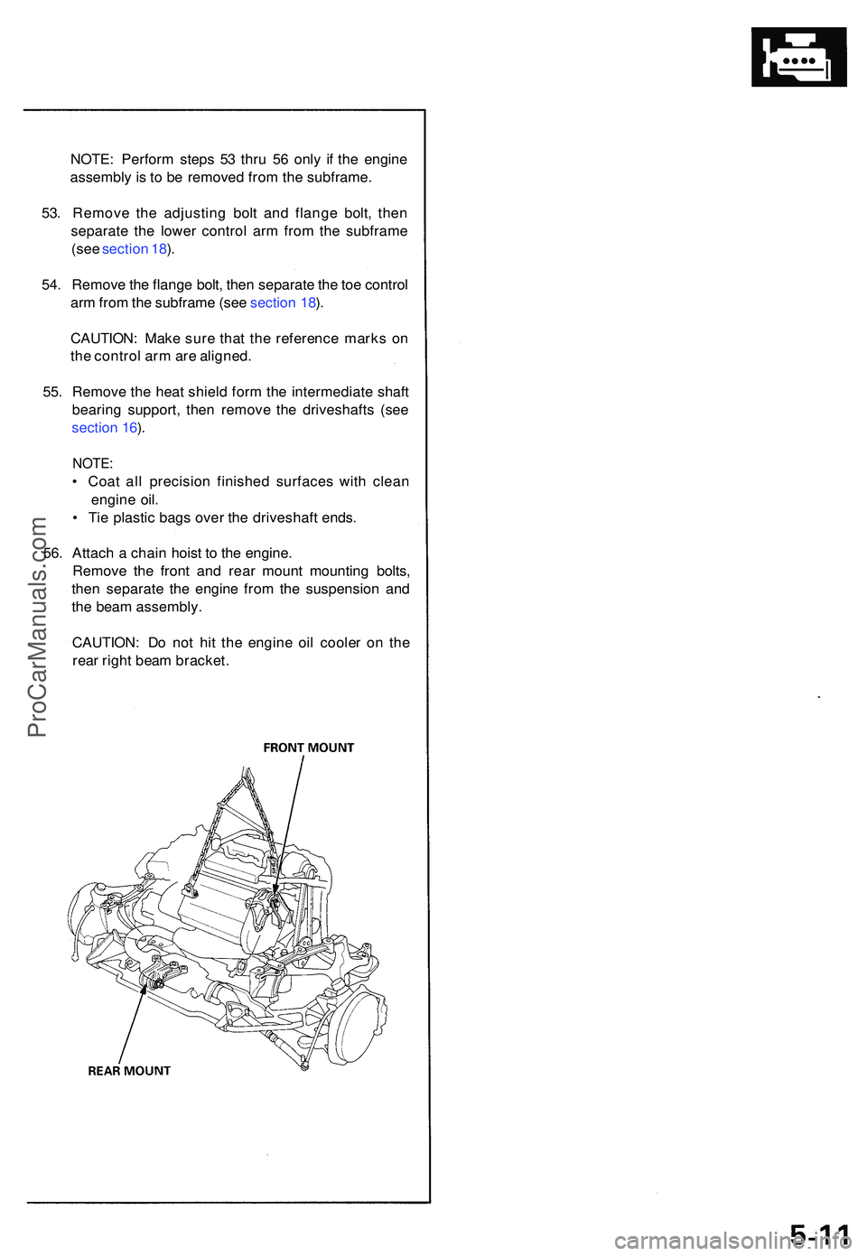
NOTE: Perfor m step s 5 3 thr u 5 6 onl y i f th e engine
assembl y i s t o b e remove d fro m th e subframe .
53 . Remov e th e adjustin g bol t an d flang e bolt , the n
separat e th e lowe r contro l ar m fro m th e subfram e
(se e sectio n 18 ).
54 . Remov e th e flang e bolt , the n separat e th e to e contro l
ar m fro m th e subfram e (se e sectio n 18 ).
CAUTION : Mak e sur e tha t th e referenc e mark s o n
th e contro l ar m ar e aligned .
55 . Remov e th e hea t shiel d for m th e intermediat e shaf t
bearin g support , the n remov e th e driveshaft s (se e
sectio n 16 ).
NOTE :
• Coa t al l precisio n finishe d surface s wit h clea n
engin e oil .
• Ti e plasti c bag s ove r th e driveshaf t ends .
56 . Attac h a chai n hois t t o th e engine .
Remov e th e fron t an d rea r moun t mountin g bolts ,
the n separat e th e engine from th e suspensio n an d
th e bea m assembly .
CAUTION : D o no t hi t th e engin e oi l coole r o n th e
rea r righ t bea m bracket .
ProCarManuals.com
Page 420 of 1503
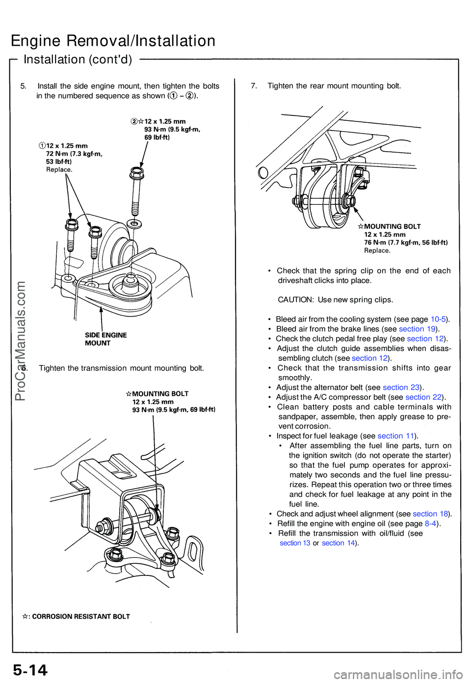
5. Instal l th e sid e engin e mount , the n tighte n th e bolt s
in th e numbere d sequenc e a s show n
Engine Removal/Installatio n
Installation (cont'd )
7. Tighte n th e rea r moun t mountin g bolt .
• Chec k tha t th e sprin g cli p o n th e en d o f eac h
driveshaf t click s int o place .
CAUTION : Us e ne w sprin g clips .
• Blee d ai r fro m th e coolin g syste m (se e pag e 10-5 ).
• Blee d ai r fro m th e brak e line s (se e sectio n 19 ).
• Chec k th e clutc h peda l fre e pla y (se e sectio n 12 ).
• Adjus t th e clutc h guid e assemblie s whe n disas -
semblin g clutc h (se e sectio n 12 ).
• Chec k tha t th e transmissio n shift s int o gea r
smoothly .
• Adjus t th e alternato r bel t (se e sectio n 23 ).
• Adjus t th e A/ C compresso r bel t (se e sectio n 22 ).
• Clea n batter y post s an d cabl e terminal s wit h
sandpaper , assemble , the n appl y greas e t o pre -
ven t corrosion .
• Inspec t fo r fue l leakag e (se e sectio n 11 ).
• Afte r assemblin g th e fue l lin e parts , tur n o n
th e ignitio n switc h (d o no t operat e th e starter )
s o tha t th e fue l pum p operate s fo r approxi -
matel y tw o second s an d th e fue l lin e pressu -
rizes . Repea t thi s operatio n tw o o r thre e time s
an d chec k fo r fue l leakag e a t an y poin t i n th e
fue l line .
• Chec k an d adjus t whee l alignmen t (se e sectio n 18 ).
• Refil l th e engin e wit h engin e oi l (se e pag e 8-4 ).
• Refil l th e transmissio n wit h oil/flui d (se e
section 1 3 o r section 14 ).
6 . Tighte n th e transmissio n moun t mountin g bolt .
ProCarManuals.com
Page 422 of 1503
VTEC
VTEC Solenoid Valve Inspection
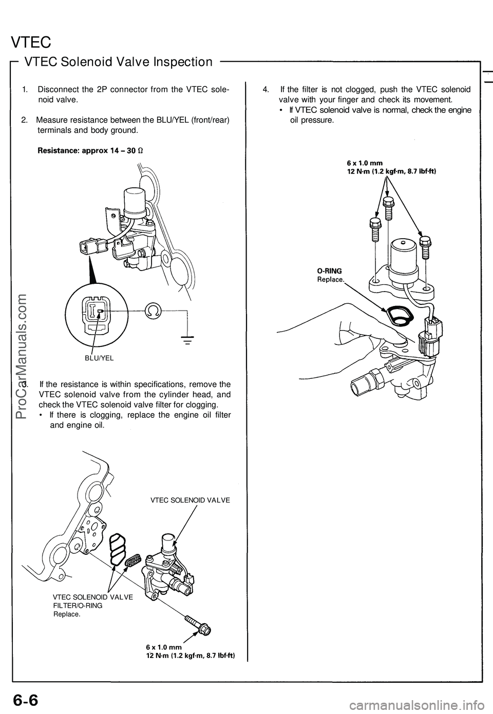
1. Disconnect the 2P connector from the VTEC sole-
noid valve.
2. Measure resistance between the BLU/YEL (front/rear)
terminals and body ground.
BLU/YEL
3. If the resistance is within specifications, remove the
VTEC solenoid valve from the cylinder head, and
check the VTEC solenoid valve filter for clogging.
• If there is clogging, replace the engine oil filter
and engine oil.
VTEC SOLENOID VALVE
VTEC SOLENOID VALVE
FILTER/O-RING
Replace.
4. If the filter is not clogged, push the VTEC solenoid
valve with your finger and check its movement.
• If VTEC solenoid valve is normal, check the engine
oil pressure.ProCarManuals.com