wiring ACURA NSX 1997 Service Repair Manual
[x] Cancel search | Manufacturer: ACURA, Model Year: 1997, Model line: NSX, Model: ACURA NSX 1997Pages: 1503, PDF Size: 57.08 MB
Page 1231 of 1503
Troubleshooting
Tips and Precautions
Before Troubleshooting
Check applicable fuses in the appropriate fuse box.
Check the battery for damage, state of charge, and
clean and tight connections.
Check the alternator belt tension.
CAUTION:
Do not quick-charge a battery unless the battery
ground cable has been disconnected.
Otherwise you will damage the alternator
diodes.
Do not attempt to crank the engine with the bat-
tery ground cable loosely connected or you will
severely damage the wiring.
Handling Connectors
Make sure the connectors are clean and have no loose
wire terminals.
Make sure multiple cavity connectors are packed with
grease (except watertight connectors).
All connectors have push-down release type locks.
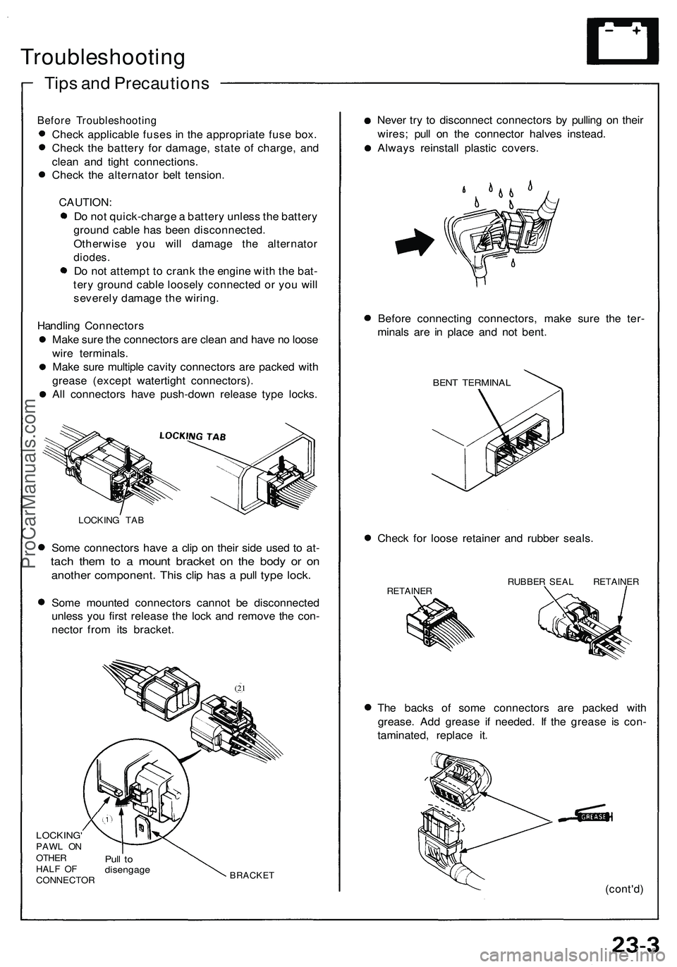
LOCKING TAB
Some connectors have a clip on their side used to at-
tach them to a mount bracket on the body or on
another component. This clip has a pull type lock.
Some mounted connectors cannot be disconnected
unless you first release the lock and remove the con-
nector from its bracket.
(21
LOCKING'
PAWL ON
OTHER
HALF OF
CONNECTOR
Pull to
disengage
BRACKET
Never try to disconnect connectors by pulling on their
wires; pull on the connector halves instead.
Always reinstall plastic covers.
Before connecting connectors, make sure the ter-
minals are in place and not bent.
BENT TERMINAL
Check for loose retainer and rubber seals.
RETAINER
RUBBER SEAL RETAINER
The backs of some connectors are packed with
grease. Add grease if needed. If the grease is con-
taminated, replace it.
(cont'd)ProCarManuals.com
Page 1456 of 1503
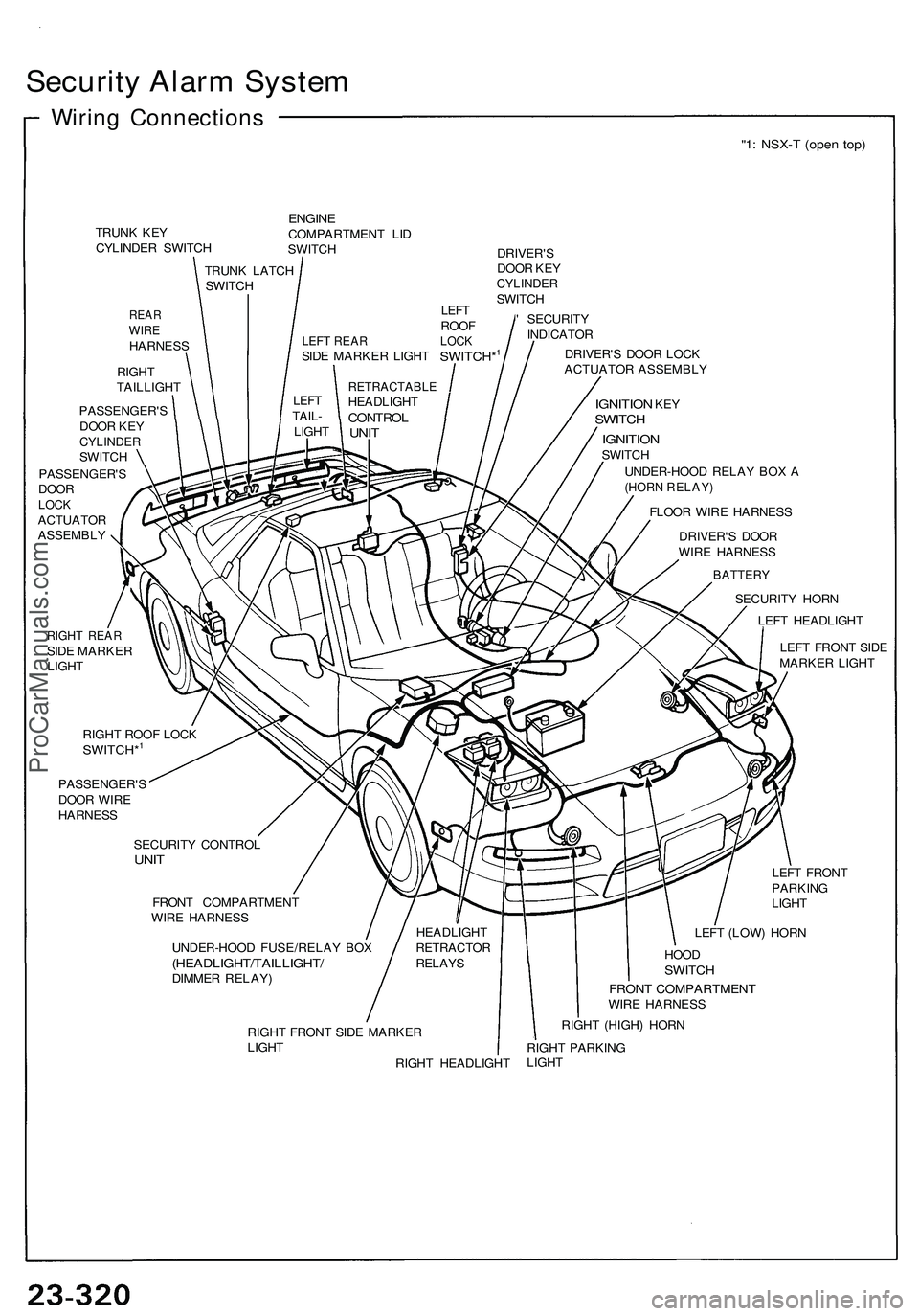
Security Alar m Syste m
Wiring Connection s
"1: NSX- T (ope n top )
TRUN K KE Y
CYLINDE R SWITC H
REARWIREHARNES S
RIGH T
TAILLIGH T
ENGINECOMPARTMEN T LI D
SWITC H
DRIVER'S
DOO R KE Y
CYLINDE RSWITCH
' SECURIT Y
INDICATO R
DRIVER' S DOO R LOC K
ACTUATO R ASSEMBL Y
PASSENGER' S
DOO R KE Y
CYLINDE RSWITCH
PASSENGER' S
DOO R
LOCKACTUATO R
ASSEMBL Y
IGNITION KEYSWITC H
IGNITIO NSWITCH
UNDER-HOO D RELA Y BO X A
(HOR N RELAY )
FLOOR WIR E HARNES S
DRIVER' S DOO R
WIR E HARNES S
RIGHT REA RSIDE MARKE R
LIGH T TRUN
K LATC H
SWITC H
RETRACTABL EHEADLIGHTCONTROLUNIT
LEF TTAIL -
LIGH T
HEADLIGHT
RETRACTO RRELAYS
BATTER Y
SECURIT Y HOR N
LEF T HEADLIGH T
LEF T FRON T SID E
MARKE R LIGH T
RIGH T ROO F LOC K
SWITCH*1
PASSENGER' S
DOO R WIR E
HARNES S
SECURIT Y CONTRO L
UNIT
FRON T COMPARTMEN T
WIR E HARNES S
UNDER-HOO D FUSE/RELA Y BO X
(HEADLIGHT/TAILLIGHT /DIMMER RELAY ) LEF
T FRON T
PARKIN G
LIGH T
LEF T (LOW ) HOR N
HOO DSWITC H
FRONT COMPARTMEN TWIRE HARNES S
RIGH T FRON T SID E MARKE R
LIGH T
RIGHT HEADLIGH TRIGH
T (HIGH ) HOR N
RIGH T PARKIN G
LIGH T
LEFT REA RSIDE MARKE R LIGH TSWITCH*1
LEFTROO FLOCK
ProCarManuals.com
Page 1473 of 1503
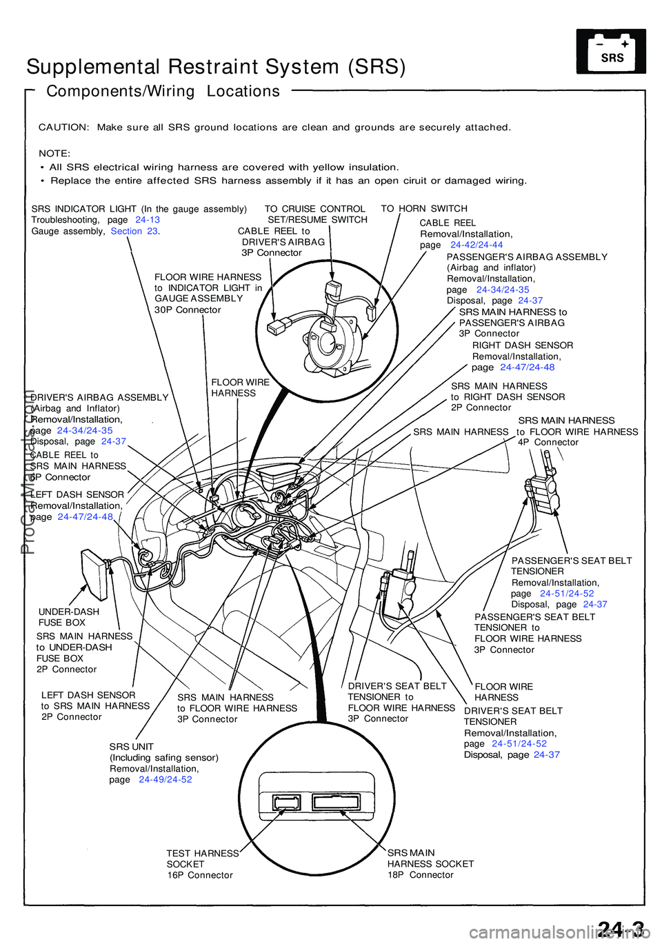
Supplemental Restrain t Syste m (SRS )
Components/Wirin g Location s
CAUTION: Mak e sur e al l SR S groun d location s ar e clea n an d ground s ar e securel y attached .
NOTE:
• Al l SR S electrica l wirin g harnes s ar e covere d wit h yello w insulation .
• Replac e th e entir e affecte d SR S harnes s assembl y i f i t ha s a n ope n cirui t o r damage d wiring .
SRS INDICATO R LIGH T (I n th e gaug e assembly ) T O CRUIS E CONTRO L
Troubleshooting , pag e 24-1 3 SET/RESUME SWITC H
Gaug e assembly , Sectio n 23 . CABL E REE L t o
DRIVER' S AIRBA G
3P Connecto r
TO HOR N SWITC H
DRIVER' S AIRBA G ASSEMBL Y
(Airba g an d Inflator )
Removal/Installation ,page 24-34/24-3 5Disposal, pag e 24-3 7
CABL E REE L t oSR S MAI N HARNES S6P Connecto r
LEFT DAS H SENSO RRemoval/Installation ,page 24-47/24-4 8
CABLE REE LRemoval/Installation ,page 24-42/24-4 4
PASSENGER' S AIRBA G ASSEMBL Y
(Airba g an d inflator )
Removal/Installation ,
pag e 24-34/24-3 5
Disposal , pag e 24-3 7
SRS MAI N HARNES S toPASSENGER' S AIRBA G
3 P Connecto r
RIGH T DAS H SENSO R
Removal/Installation ,
page 24-47/24-4 8
SRS MAI N HARNES S
t o RIGH T DAS H SENSO R
2 P Connecto r
SRS MAI N HARNES SSRS MAI N HARNES S t o FLOO R WIR E HARNES S
4 P Connecto r
UNDER-DAS H
FUS E BO X
SR S MAI N HARNES S
to UNDER-DAS HFUSE BO X
2 P Connecto r
LEF T DAS H SENSO R
t o SR S MAI N HARNES S
2 P Connecto r
SRS UNI T(Includin g safin g sensor )Removal/Installation ,
pag e 24-49/24-5 2 PASSENGER'
S SEA T BEL T
TENSIONE R
Removal/Installation ,
pag e 24-51/24-5 2
Disposal , pag e 24-3 7
PASSENGER' S SEA T BEL T
TENSIONE R t o
FLOO R WIR E HARNES S
3 P Connecto r
FLOO R WIR E
HARNES S
DRIVER' S SEA T BEL T
TENSIONE R
Removal/Installation ,page 24-51/24-5 2Disposal, pag e 24-3 7
TEST HARNES SSOCKET16P Connecto r
SRS MAI NHARNES S SOCKE T
18 P Connecto r
SR
S MAI N HARNES S
t o FLOO R WIR E HARNES S
3 P Connecto r DRIVER'
S SEA T BEL T
TENSIONE R t o
FLOO R WIR E HARNES S
3 P Connecto r
FLOO
R WIR E
HARNES S
FLOOR WIR E HARNES S
t o INDICATO R LIGH T i n
GAUGE ASSEMBL Y
30P Connecto r
ProCarManuals.com
Page 1478 of 1503
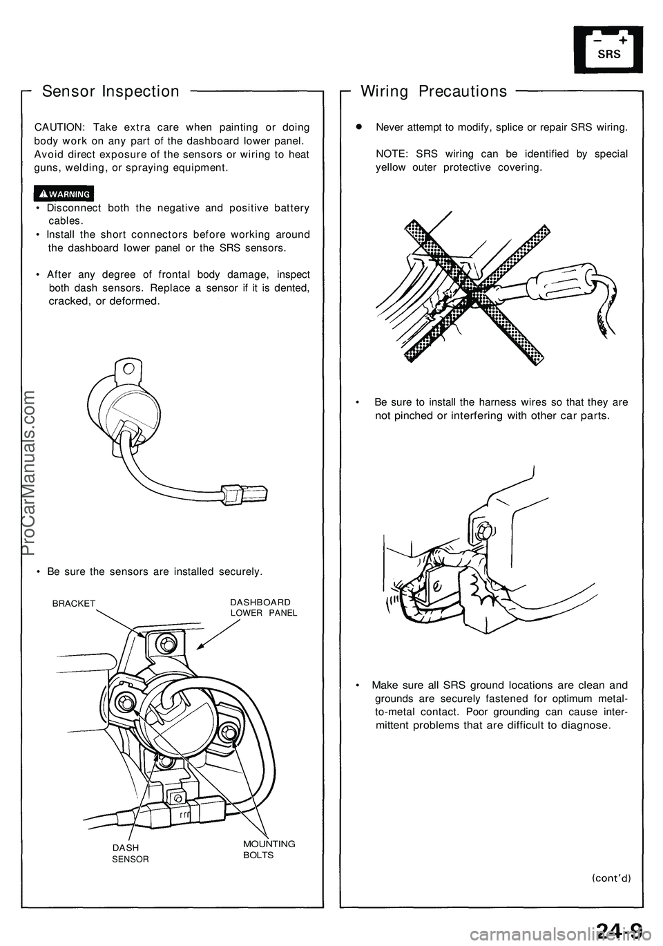
Sensor Inspection
CAUTION: Take extra care when painting or doing
body work on any part of the dashboard lower panel.
Avoid direct exposure of the sensors or wiring to heat
guns, welding, or spraying equipment.
• Disconnect both the negative and positive battery
cables.
• Install the short connectors before working around
the dashboard lower panel or the SRS sensors.
• After any degree of frontal body damage, inspect
both dash sensors. Replace a sensor if it is dented,
cracked, or deformed.
• Be sure the sensors are installed securely.
BRACKET
DASHBOARD
LOWER PANEL
MOUNTING
BOLTS
Wiring Precautions
Never attempt to modify, splice or repair SRS wiring.
NOTE: SRS wiring can be identified by special
yellow outer protective covering.
• Be sure to install the harness wires so that they are
not pinched or interfering with other car parts.
• Make sure all SRS ground locations are clean and
grounds are securely fastened for optimum metal-
to-metal contact. Poor grounding can cause inter-
mittent problems that are difficult to diagnose.
DASH
SENSORProCarManuals.com
Page 1483 of 1503
Troubleshooting
Self-diagnosis Functio n
The SR S uni t include s a self-diagnosi s function . I f ther e
i s a failur e in th e sensors , SR S unit , inflator , o r thei r cir -
cuits , th e SR S indicato r ligh t i n th e gaug e assembl y
goe s ON .
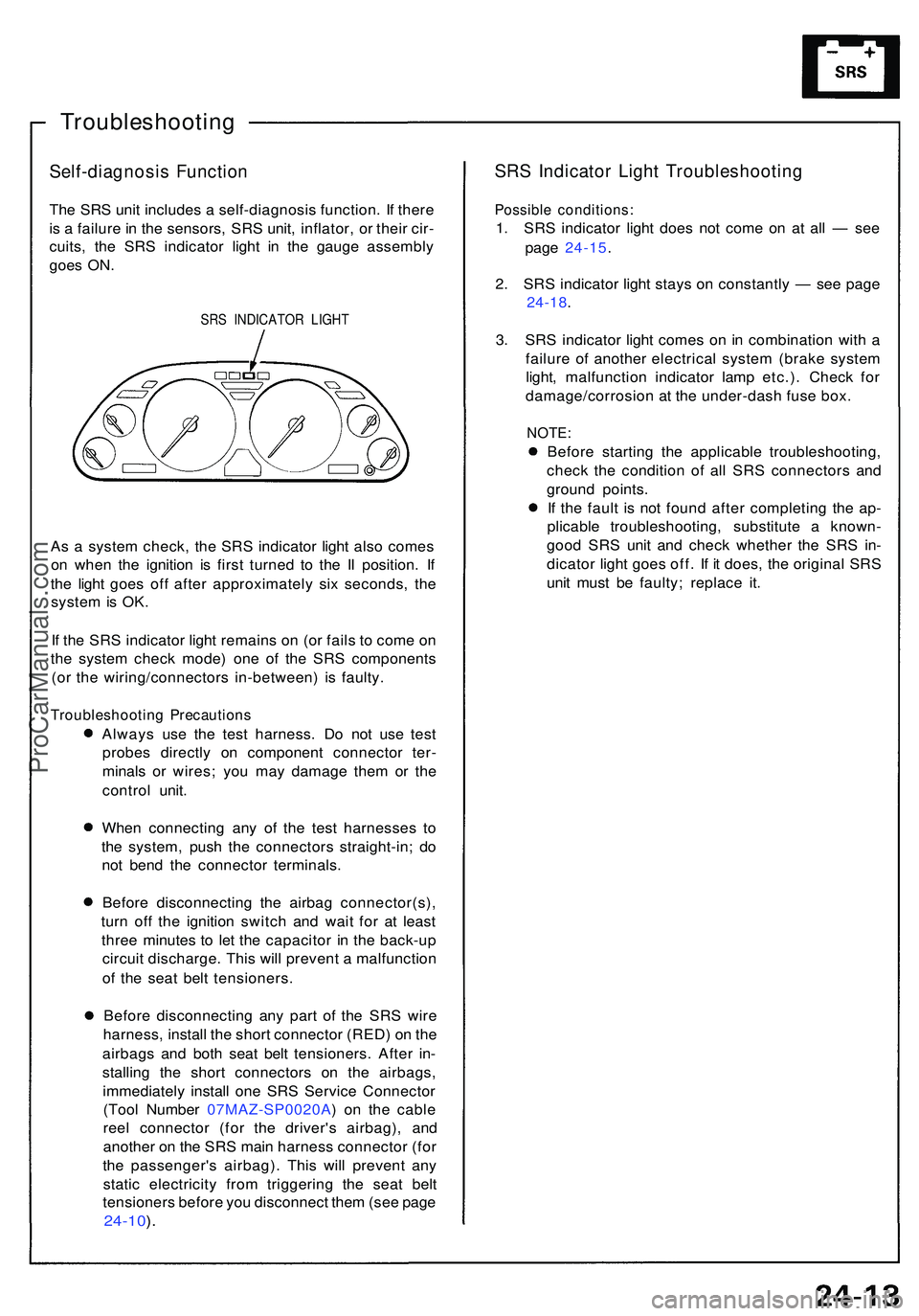
SRS INDICATO R LIGH T
As a syste m check , th e SR S indicato r ligh t als o come s
o n whe n th e ignitio n i s firs t turne d t o th e I I position . I f
th e ligh t goe s of f afte r approximatel y si x seconds , th e
syste m is OK .
I f th e SR S indicato r ligh t remain s o n (o r fail s t o com e o n
th e syste m chec k mode ) on e o f th e SR S component s
(o r th e wiring/connector s in-between ) i s faulty .
Troubleshootin g Precaution s
Always us e th e tes t harness . D o no t us e tes t
probe s directl y o n componen t connecto r ter -
minal s o r wires ; yo u ma y damag e the m o r th e
contro l unit .
Whe n connectin g an y o f th e tes t harnesse s t o
th e system , pus h th e connector s straight-in ; d o
no t ben d th e connecto r terminals .
Befor e disconnectin g th e airba g connector(s) ,
tur n of f th e ignitio n switc h an d wai t fo r a t leas t
thre e minute s t o le t th e capacito r i n th e back-u p
circui t discharge . Thi s wil l preven t a malfunctio n
o f th e sea t bel t tensioners .
Befor e disconnectin g an y par t o f th e SR S wir e
harness , instal l th e shor t connecto r (RED ) o n th e
airbag s an d bot h sea t bel t tensioners . Afte r in -
stallin g th e shor t connector s o n th e airbags ,
immediatel y instal l on e SR S Servic e Connecto r
(Too l Numbe r 07MAZ-SP0020A ) o n th e cabl e
ree l connecto r (fo r th e driver' s airbag) , an d
anothe r o n th e SR S mai n harnes s connecto r (fo r
th e passenger' s airbag) . Thi s wil l preven t an y
stati c electricit y fro m triggerin g th e sea t bel t
tensioner s befor e yo u disconnec t the m (se e pag e
24-10 ).
SR S Indicato r Ligh t Troubleshootin g
Possible conditions :
1. SR S indicato r ligh t doe s no t com e o n a t al l — se e
pag e 24-15 .
2 . SR S indicato r ligh t stay s o n constantl y — se e pag e
24-18 .
3 . SR S indicato r ligh t come s o n in combinatio n wit h a
failur e o f anothe r electrica l syste m (brak e syste m
light , malfunctio n indicato r lam p etc.) . Chec k fo r
damage/corrosio n a t th e under-das h fus e box .
NOTE :
Before startin g th e applicabl e troubleshooting ,
chec k th e conditio n o f al l SR S connector s an d
groun d points .
I f th e faul t i s no t foun d afte r completin g th e ap -
plicabl e troubleshooting , substitut e a known -
goo d SR S uni t an d chec k whethe r th e SR S in -
dicato r ligh t goe s off . I f i t does , th e origina l SR S
uni t mus t b e faulty ; replac e it .
ProCarManuals.com
Page 1486 of 1503
Airbag Assembly Installation
CAUTION:
• Be sure to install the SRS wiring so that it is not pin-
ched or interfering with other car parts.
• Be sure the battery cables are disconnected.
• After completing repair work, be sure to remove the
short connectors (RED) and reconnect all the con-
nectors.
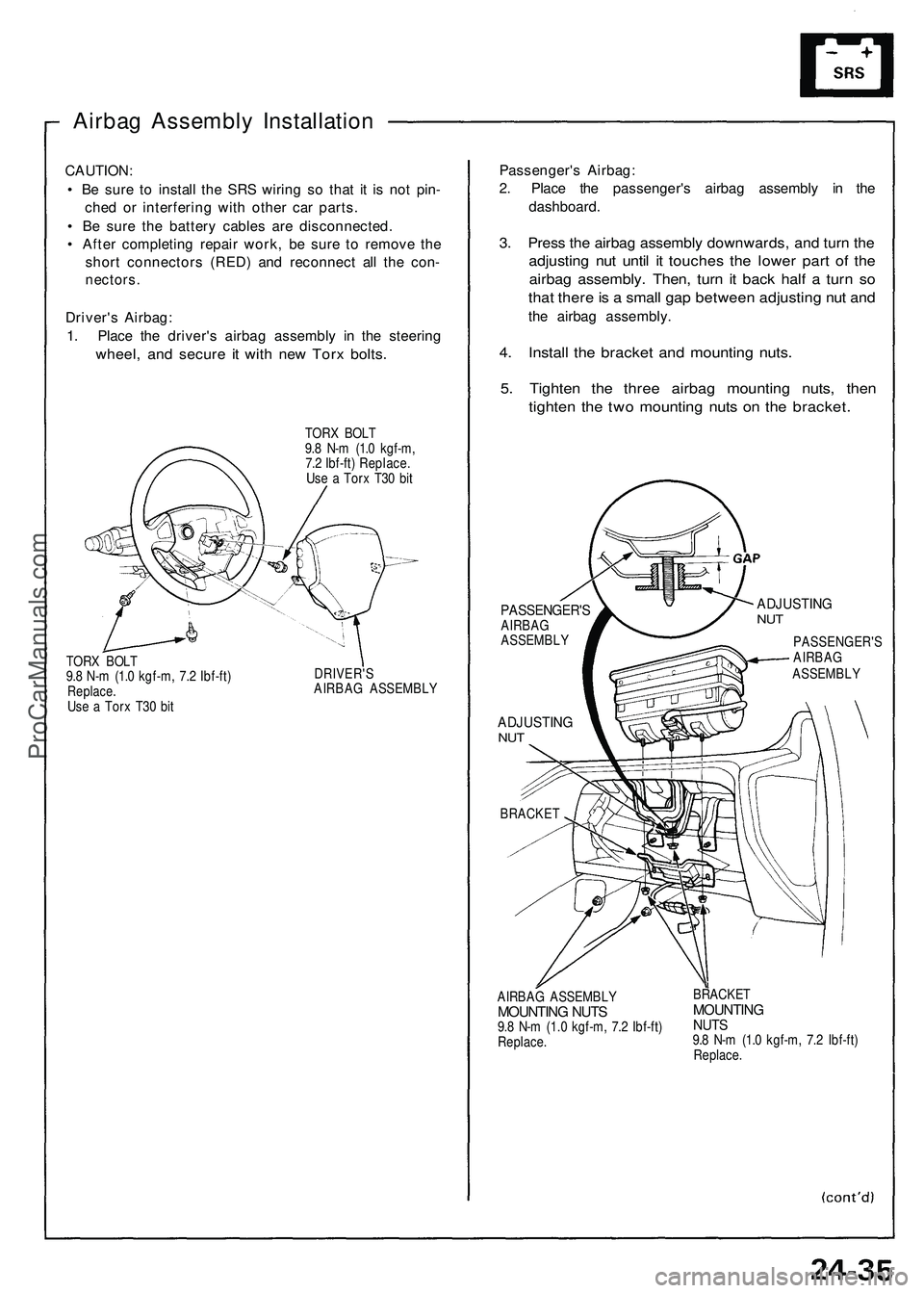
Driver's Airbag:
1. Place the driver's airbag assembly in the steering
wheel, and secure it with new Torx bolts.
TORX BOLT
9.8 N-m (1.0 kgf-m,
7.2 Ibf-ft) Replace.
Use a Torx T30 bit
TORX BOLT
9.8 N-m (1.0 kgf-m, 7.2 Ibf-ft)
Replace.
Use a Torx T30 bit
DRIVER'S
AIRBAG ASSEMBLY
Passenger's Airbag:
2. Place the passenger's airbag assembly in the
dashboard.
3. Press the airbag assembly downwards, and turn the
adjusting nut until it touches the lower part of the
airbag assembly. Then, turn it back half a turn so
that there is a small gap between adjusting nut and
the airbag assembly.
4. Install the bracket and mounting nuts.
5. Tighten the three airbag mounting nuts, then
tighten the two mounting nuts on the bracket.
PASSENGER'S
AIRBAG
ASSEMBLY
ADJUSTING
NUT
BRACKET
ADJUSTING
NUT
PASSENGER'S
AIRBAG
ASSEMBLY
AIRBAG ASSEMBLY
MOUNTING NUTS
9.8 N-m (1.0 kgf-m, 7.2 Ibf-ft)
Replace.
BRACKET
MOUNTING
NUTS
9.8 N-m (1.0 kgf-m, 7.2 Ibf-ft)
Replace.ProCarManuals.com
Page 1498 of 1503
Dash Senso r Remova l
CAUTION :
D o no t damag e th e senso r wiring .
D o no t instal l use d SR S part s fro m anothe r car ,
Whe n repairin g a n SRS , us e onl y ne w parts .
Carefull y inspec t th e das h sensor s fo r sign s o f bein g
droppe d o r improperl y handled , suc h a s dents ,
crack s o r deformation .
1 . Disconnec t th e batter y negativ e cable , the n th e
positiv e cable .
2 . Befor e disconnectin g an y par t o f th e SR S wir e
harness , instal l th e shor t connector s (RED ) (se e pag e
24-10 ).
3 . Remov e th e dashboar d lowe r cover .
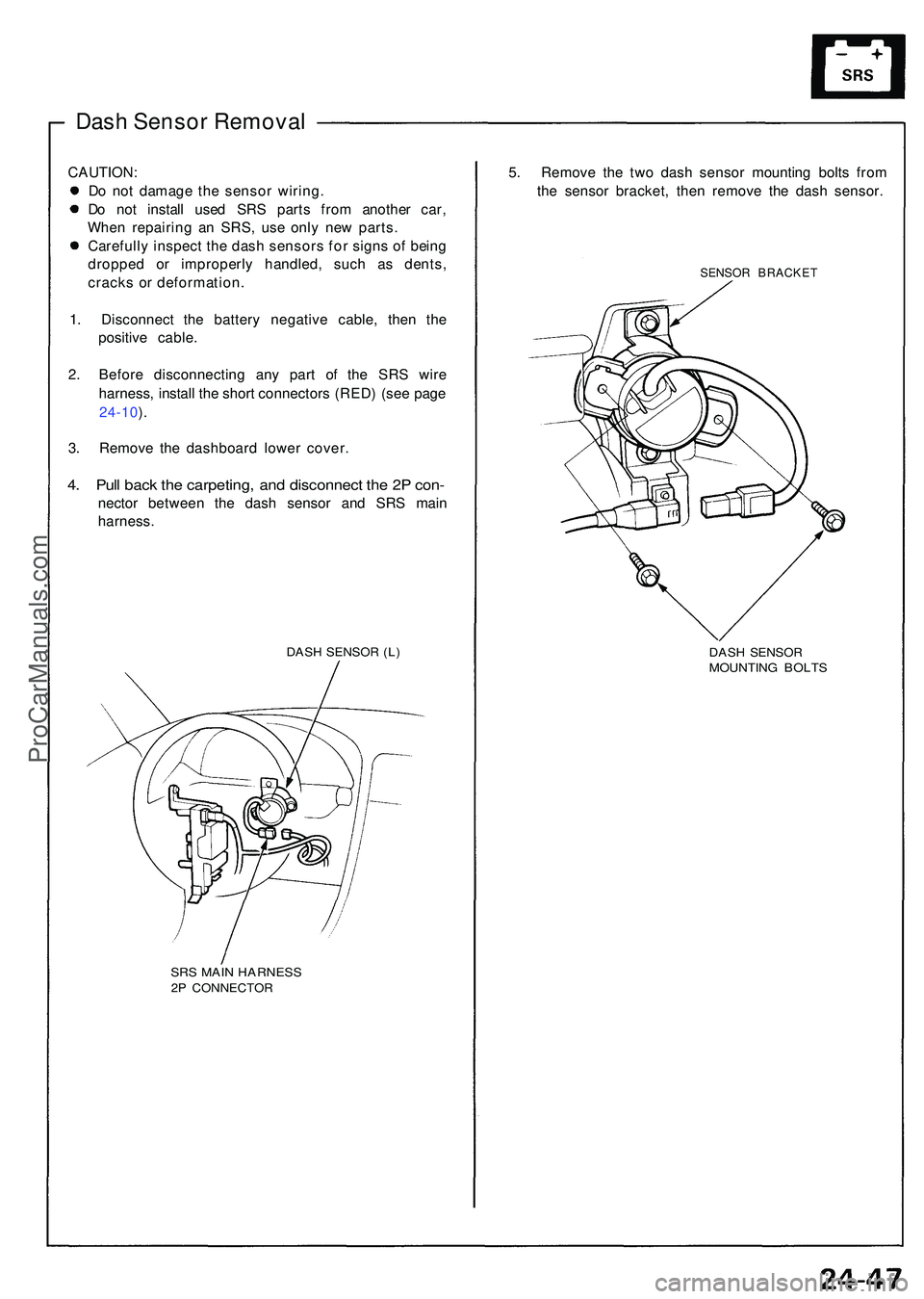
4. Pul l bac k th e carpeting , an d disconnec t th e 2 P con -
necto r betwee n th e das h senso r an d SR S mai n
harness .
DASH SENSO R (L )
SR S MAI N HARNES S2P CONNECTO R
5. Remov e th e tw o das h senso r mountin g bolt s fro m
th e senso r bracket , the n remov e th e das h sensor .
SENSOR BRACKE T
DASH SENSO RMOUNTIN G BOLT S
ProCarManuals.com
Page 1501 of 1503
Supplemental Restraint System (SRS)
SRS Unit Assembly Installation
CAUTION: Be sure to install the SRS wiring so that it is
not pinched or interfering with other car parts.
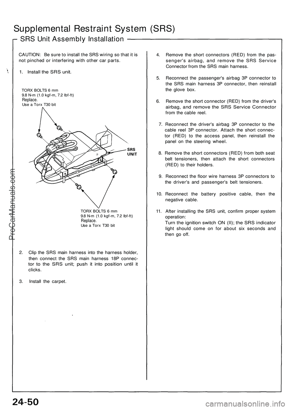
1. Install the SRS unit.
TORX BOLTS 6 mm
9.8 N-m (1.0 kgf-m, 7.2 Ibf-ft)
Replace.
Use a Torx T30 bit
TORX BOLTS 6 mm
9.8 N-m (1.0 kgf-m, 7.2 Ibf-ft)
Replace.
Use a Torx T30 bit
2. Clip the SRS main harness into the harness holder,
then connect the SRS main harness 18P connec-
tor to the SRS unit; push it into position until it
clicks.
3. Install the carpet.
4. Remove the short connectors (RED) from the pas-
senger's airbag, and remove the SRS Service
Connector from the SRS main harness.
5. Reconnect the passenger's airbag 3P connector to
the SRS main harness 3P connector, then reinstall
the glove box.
6. Remove the short connector (RED) from the driver's
airbag, and remove the SRS Service Connector
from the cable reel.
7. Reconnect the driver's airbag 3P connector to the
cable reel 3P connector. Attach the short connec-
tor (RED) to the access panel, then reinstall the
panel on the steering wheel.
8. Remove the short connectors (RED) from both seat
belt tensioners, then attach the short connectors
(RED) to their holders.
9. Reconnect the floor wire harness 3P connectors to
the driver's and passenger's belt tensioners.
10. Reconnect the battery positive cable, then the
negative cable.
11. After installing the SRS unit, confirm proper system
operation:
Turn the ignition switch ON (II); the SRS indicator
light should come on for about six seconds and
then go off.ProCarManuals.com