sensor ACURA RL KA9 1996 Service Repair Manual
[x] Cancel search | Manufacturer: ACURA, Model Year: 1996, Model line: RL KA9, Model: ACURA RL KA9 1996Pages: 1954, PDF Size: 61.44 MB
Page 811 of 1954
Road Tes t
NOTE : War m u p th e engin e to norma l operatin g temperatur e (th e radiato r fa n come s on) .
1. Appl y parkin g brak e an d bloc k th e wheels . Star t th e engine , the n shif t t o positio n whil e pressin g th e brak e pedal .
Pres s th e accelerato r peda l an d releas e it suddenly . Th e engin e shoul d no t stall .
2. Repea t th e sam e tes t i n position .
3. Test-driv e th e vehicl e o n th e fla t roa d in position . Chec k tha t th e shif t point s occu r a t th e approximat e speed s
shown o n th e nex t page . Als o chec k fo r abnorma l nois e an d clutc h slippage .
NOTE : Throttl e positio n senso r voltag e represent s th e throttl e opening .
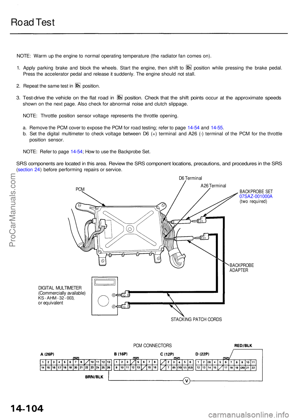
a . Remov e th e PC M cove r t o expos e th e PC M fo r roa d testing ; refe r t o pag e 14-5 4 an d 14-55 .
b . Se t th e digita l multimete r t o chec k voltag e betwee n D 6 (+ ) termina l an d A2 6 (- ) termina l o f th e PC M fo r th e throttl e
positio n sensor .
NOTE : Refe r t o pag e 14-54 ; Ho w to us e th e Backprob e Set .
SRS component s ar e locate d in thi s area . Revie w th e SR S componen t locations , precautions , an d procedure s in th e SR S
(sectio n 24 ) befor e performin g repair s o r service .
PCM
D6 Termina l
DIGITAL MULTIMETE R(Commercially available )KS - AH M - 3 2 - 003 ,or equivalen t
BACKPROB E SE T07SAZ-001000A(two required )
BACKPROB EADAPTER
STACKIN G PATC H CORD S
A26 Termina l
PCM CONNECTOR S
ProCarManuals.com
Page 840 of 1954
1. Remov e th e mainshaf t an d countershaf t spee d sen -
sors fro m th e transmissio n housing .
2. Remov e th e 1 6 bolts securin g th e transmissio n
housin g wit h th e transmissio n hanger , harnes s
clam p bracket , an d spee d senso r connecto r bracket .
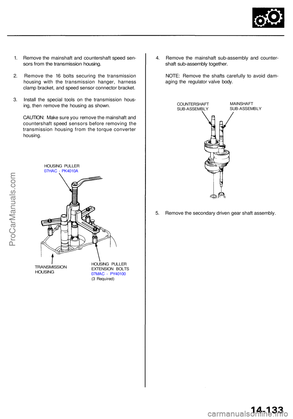
3 . Instal l th e specia l tool s o n th e transmissio n hous -
ing , the n remov e th e housin g a s shown .
CAUTION : Mak e sur e yo u remov e th e mainshaf t an d
countershaf t spee d sensor s befor e removin g th e
transmissio n housin g fro m th e torqu e converte r
housing.
HOUSIN G PULLE R
07HA C - PK4010 A
TRANSMISSIO NHOUSING
HOUSING PULLE R
EXTENSIO N BOLT S
07MA C - PY4010 0
( 3 Required )
4. Remov e th e mainshaf t sub-assembl y an d counter -
shaft sub-assembl y together .
NOTE: Remov e th e shaft s carefull y t o avoi d dam-
agin g th e regulato r valv e body .
COUNTERSHAF T
SUB-ASSEMBL YMAINSHAF
T
SUB-ASSEMBL Y
5. Remov e th e secondar y drive n gea r shaf t assembly .
ProCarManuals.com
Page 893 of 1954
Transmission
Reassembly (cont'd )
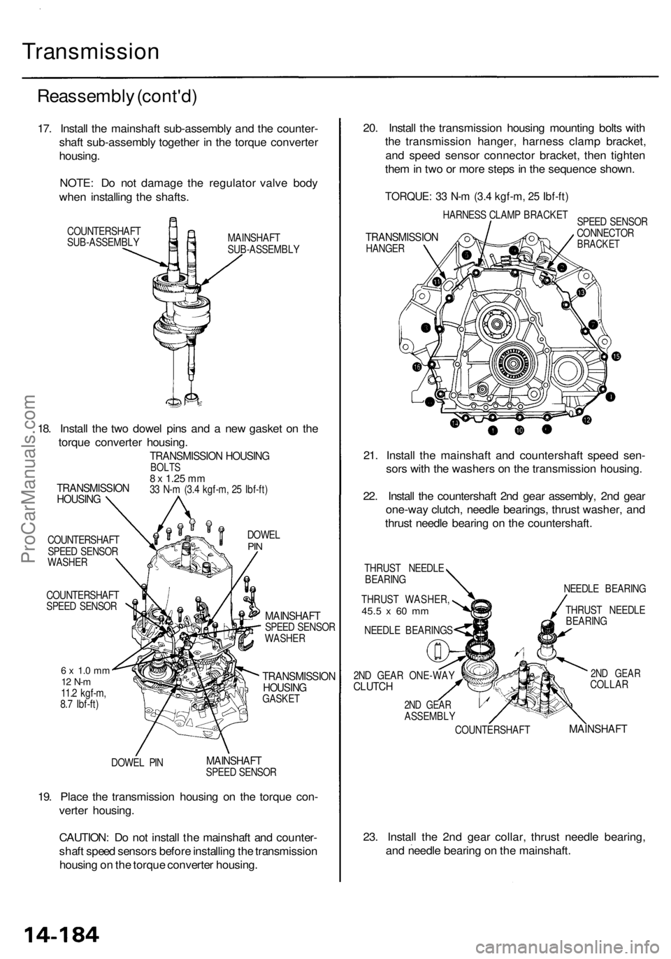
17. Instal l th e mainshaf t sub-assembl y an d th e counter -
shaf t sub-assembl y togethe r i n th e torqu e converte r
housing .
NOTE : D o no t damag e th e regulato r valv e bod y
whe n installin g th e shafts .
COUNTERSHAF T
SUB-ASSEMBL Y MAINSHAF
T
SUB-ASSEMBL Y
COUNTERSHAF T
SPEE D SENSO R
WASHE R
COUNTERSHAF T
SPEE D SENSO R
6 x 1. 0 m m12 N- m11.2 kgf-m ,
8. 7 Ibf-ft )
DOWE L PI N DOWE
L
PIN
MAINSHAF TSPEED SENSO R
WASHE R
TRANSMISSIO NHOUSINGGASKET
MAINSHAF TSPEED SENSO R
19. Plac e th e transmissio n housin g o n th e torqu e con -
verte r housing .
CAUTION : D o no t instal l th e mainshaf t an d counter -
shaf t spee d sensor s befor e installin g th e transmissio n
housin g o n th e torqu e converte r housing . 20
. Instal l th e transmissio n housin g mountin g bolt s wit h
th e transmissio n hanger , harnes s clam p bracket ,
an d spee d senso r connecto r bracket , the n tighte n
the m in tw o o r mor e step s in th e sequenc e shown .
TORQUE : 3 3 N- m (3. 4 kgf-m , 2 5 Ibf-ft )
HARNES S CLAM P BRACKE T
TRANSMISSIO NHANGER SPEE
D SENSO R
CONNECTO RBRACKET
21. Instal l th e mainshaf t an d countershaf t spee d sen -
sor s wit h th e washer s o n th e transmissio n housing .
22 . Instal l th e countershaf t 2n d gea r assembly , 2n d gea r
one-wa y clutch , needl e bearings , thrus t washer , an d
thrus t needl e bearin g o n th e countershaft .
THRUST NEEDL E
BEARIN G
THRUS T WASHER ,
45.5 x 60 m m
NEEDL E BEARING S NEEDL
E BEARIN G
COUNTERSHAF TTHRUS
T NEEDL E
BEARIN G
2ND GEA RCOLLA R
MAINSHAF T
23. Instal l th e 2n d gea r collar , thrus t needl e bearing ,
an d needl e bearin g o n th e mainshaft .
TRANSMISSIO NHOUSING
TRANSMISSIO N HOUSIN GBOLTS8 x 1.2 5 mm33 N- m (3. 4 kgf-m , 2 5 Ibf-ft )
18. Instal l th e tw o dowe l pin s an d a ne w gaske t o n th e
torqu e converte r housing .
2ND GEA R ONE-WA YCLUTCH
2ND GEA RASSEMBL Y
ProCarManuals.com
Page 917 of 1954
Differential Assembl y
Removal (cont'd )
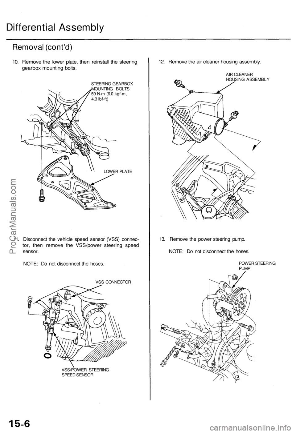
10. Remov e th e lowe r plate , the n reinstal l th e steerin g
gearbo x mountin g bolts .
STEERIN G GEARBO XMOUNTING BOLT S
5 9 N- m (6. 0 kgf-m ,
4. 3 Ibf-ft )
LOWE R PLAT E
11. Disconnec t th e vehicl e spee d senso r (VSS ) connec -
tor , the n remov e th e VSS/powe r steerin g spee d
sensor .
NOTE : D o no t disconnec t th e hoses .
VSS CONNECTO R
VSS/POWE R STEERIN G
SPEE D SENSO R
12. Remov e th e ai r cleane r housin g assembly .
AIR CLEANE RHOUSING ASSEMBL Y
13. Remov e th e powe r steerin g pump .
NOTE : D o no t disconnec t th e hoses .
POWER STEERIN G
PUM P
ProCarManuals.com
Page 941 of 1954
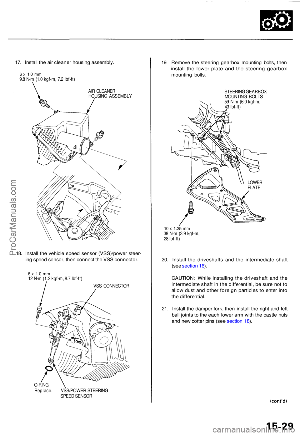
17. Instal l th e ai r cleane r housin g assembly .
6 x 1. 0 m m9.8 N- m (1. 0 kgf-m , 7. 2 Ibf-ft )
AIR CLEANE RHOUSING ASSEMBL Y
18. Instal l th e vehicl e spee d senso r (VSS)/powe r steer -
in g spee d sensor , the n connec t th e VS S connector .
6 x 1. 0 m m12 N- m (1. 2 kgf-m , 8. 7 Ibf-ft )
VSS CONNECTO R
O-RIN G
Replace . VSS/POWE R STEERIN G
SPEE D SENSO R
19. Remov e th e steerin g gearbo x mountin g bolts , the n
instal l th e lowe r plat e an d th e steerin g gearbo x
mounting bolts .
STEERIN G GEARBO XMOUNTING BOLT S59 N- m (6. 0 kgf-m ,
4 3 Ibf-ft )
10 x 1.2 5 mm38 N- m (3. 9 kgf-m ,
2 8 Ibf-ft )
20. Instal l th e driveshaft s an d th e intermediat e shaf t
(se e sectio n 16 ).
CAUTION : Whil e installin g th e driveshaf t an d th e
intermediat e shaf t i n th e differential , b e sur e no t t o
allo w dus t an d othe r foreig n particle s t o ente r int o
th e differential .
21 . Instal l th e dampe r fork , the n instal l th e righ t an d lef t
bal l joint s t o th e eac h lowe r ar m wit h th e castl e nut s
an d ne w cotte r pin s (se e sectio n 18 ).
LOWE RPLATE
ProCarManuals.com
Page 977 of 1954
Inspection an d Adjustmen t
Steering Operatio n
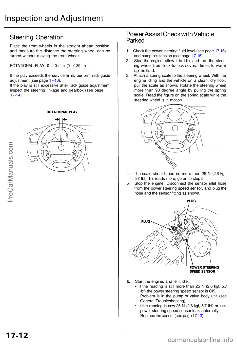
Place th e fron t wheel s i n th e straigh t ahea d position ,
an d measur e th e distanc e th e steerin g whee l ca n b e
turne d withou t movin g th e fron t wheels .
ROTATIONA L PLAY : 0 - 1 0 m m (0 - 0.3 9 in )
If th e pla y exceed s th e servic e limit, perfor m rack guid e
adjustmen t (se e pag e 17-16 ).
I f th e pla y i s stil l excessiv e afte r rac k guid e adjustment ,
inspec t th e steerin g linkag e an d gearbo x (se e pag e
17-14 ).
Powe r Assis t Chec k wit h Vehicl e
Parked
1. Chec k th e powe r steerin g flui d leve l (se e pag e 17-16 )
an d pum p bel t tensio n (se e pag e 17-15 ).
2 . Star t th e engine , allo w it t o idle , an d tur n th e steer -
in g whee l fro m lock-to-loc k severa l time s t o war m
up th e fluid .
3. Attac h a sprin g scal e to th e steerin g wheel . Wit h th e
engin e idlin g an d th e vehicl e o n a clean , dr y floor ,
pul l th e scal e a s shown . Rotat e th e steerin g whee l
mor e tha n 9 0 degre e angl e b y pullin g th e sprin g
scale . Rea d th e figur e o n th e sprin g scal e whil e th e
steerin g whee l i s in motion .
4 . Th e scal e shoul d rea d n o mor e the n 2 5 N (2. 6 kgf ,
5. 7 Ibf) . I f i t read s more , g o o n to ste p 5 .
5 . Sto p th e engine . Disconnec t th e senso r inle t hos e
fro m th e powe r steerin g spee d sensor , an d plu g th e
hos e an d th e senso r fittin g a s shown .
6 . Star t th e engine , an d le t i t idle .
• I f th e readin g i s stil l mor e tha n 2 5 N (2. 6 kgf , 5. 7
Ibf ) th e powe r steerin g spee d senso r i s OK .
Proble m is i n th e pum p o r valv e bod y uni t (se e
Genera l Troubleshooting) .
• I f th e readin g is no w 2 5 N (2. 6 kgf , 5. 7 Ibf ) o r less ,
powe r steerin g spee d senso r leak s internally .
Replac e th e senso r (se e pag e 17-13 ).
ProCarManuals.com
Page 978 of 1954
Assist Chec k a t Roa d Spee d
Assist (excessivel y ligh t steering ) a t hig h speed :
1 . Chec k th e powe r steerin g flui d leve l (se e pag e 17-16 ),
an d pum p bel t tensio n (se e pag e 17-15 ).
2 . Star t th e engine , allo w it t o idle , an d tur n th e steerin g
whee l fro m lock-to-loc k severa l time s t o war m u p th e
fluid .
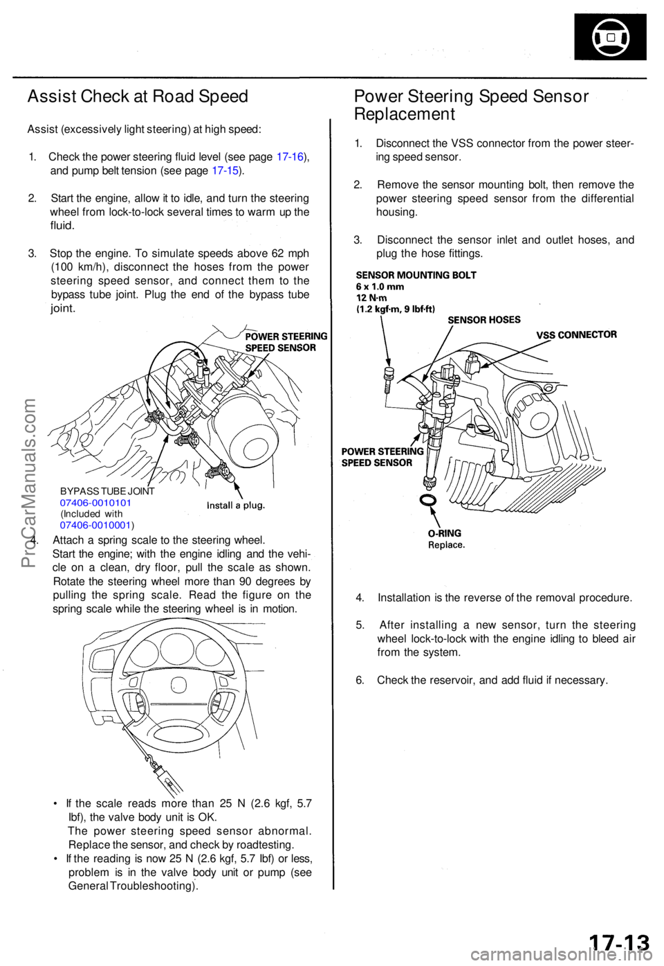
3. Sto p th e engine . T o simulat e speed s abov e 6 2 mp h
(10 0 km/h) , disconnec t th e hose s fro m th e powe r
steerin g spee d sensor , an d connec t the m to th e
bypas s tub e joint . Plu g th e en d o f th e bypas s tub e
joint .
Powe r Steerin g Spee d Senso r
Replacemen t
1. Disconnec t th e VS S connecto r fro m th e powe r steer -
in g spee d sensor .
2 . Remov e th e senso r mountin g bolt , the n remov e th e
powe r steerin g spee d senso r fro m th e differentia l
housing .
3 . Disconnec t th e senso r inle t an d outle t hoses , an d
plu g th e hos e fittings .
4 . Installatio n is th e revers e o f th e remova l procedure .
5 . Afte r installin g a ne w sensor , tur n th e steerin g
whee l lock-to-loc k wit h th e engine idling t o blee d ai r
fro m th e system .
6 . Chec k th e reservoir , an d ad d flui d if necessary .
BYPASS TUB E JOIN T07406-001010 1(Included wit h07406-0010001 )
4. Attac h a sprin g scal e to th e steerin g wheel .
Star t th e engine ; wit h th e engin e idlin g an d th e vehi -
cl e o n a clean , dr y floor , pul l th e scal e a s shown .
Rotat e th e steerin g whee l mor e tha n 9 0 degree s b y
pullin g th e sprin g scale . Rea d th e figur e o n th e
sprin g scal e whil e th e steerin g whee l i s i n motion .
• I f th e scal e read s mor e tha n 2 5 N (2. 6 kgf , 5. 7
Ibf) , th e valv e bod y uni t i s OK .
Th e powe r steerin g spee d senso r abnormal .
Replac e th e sensor , an d chec k b y roadtesting .
• I f th e readin g is no w 2 5 N (2. 6 kgf , 5. 7 Ibf ) o r less ,
proble m is i n th e valv e bod y uni t o r pum p (se e
Genera l Troubleshooting) .
ProCarManuals.com
Page 985 of 1954
Steering Colum n
Removal/Installatio n
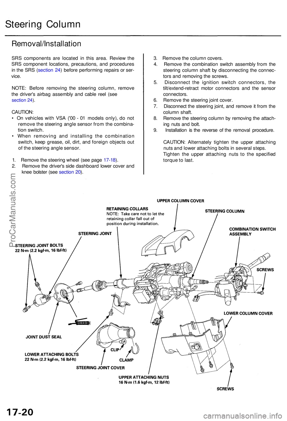
SRS component s ar e locate d i n thi s area . Revie w th e
SR S componen t locations , precautions , an d procedure s
i n th e SR S (sectio n 24 ) befor e performin g repair s o r ser -
vice .
NOTE : Befor e removin g th e steerin g column , remov e
th e driver' s airba g assembl y an d cabl e ree l (se e
section 24 ).
CAUTION :
• O n vehicle s wit h VS A ('0 0 - 0 1 model s only) , d o no t
remov e th e steerin g angl e senso r fro m th e combina -
tion switch .
• Whe n removin g an d installin g th e combinatio n
switch , kee p grease , oil , dirt , an d foreig n object s ou t
o f th e steerin g angl e sensor .
1 . Remov e th e steerin g whee l (se e pag e 17-18 ).
2 . Remov e th e driver' s sid e dashboar d lowe r cove r an d
kne e bolste r (se e sectio n 20 ). 3
. Remov e th e colum n covers .
4 . Remov e th e combinatio n switc h assembl y fro m th e
steerin g colum n shaf t b y disconnectin g th e connec -
tor s an d removin g th e screws .
5 . Disconnec t th e ignitio n switc h connectors , th e
tilt/extend-retrac t moto r connector s an d th e senso r
connectors .
6 . Remov e th e steerin g join t cover .
7 . Disconnec t th e steerin g joint , an d remov e it fro m th e
colum n shaft .
8 . Remov e th e steerin g colum n b y removin g th e attach -
in g nut s an d bolt .
9 . Installatio n i s th e revers e o f th e remova l procedure .
CAUTION : Alternatel y tighte n th e uppe r attachin g
nut s an d lowe r attachin g bolt s in severa l steps .
Tighte n th e uppe r attachin g nut s t o th e specifie d
torqu e to last .
ProCarManuals.com
Page 987 of 1954
Inspection
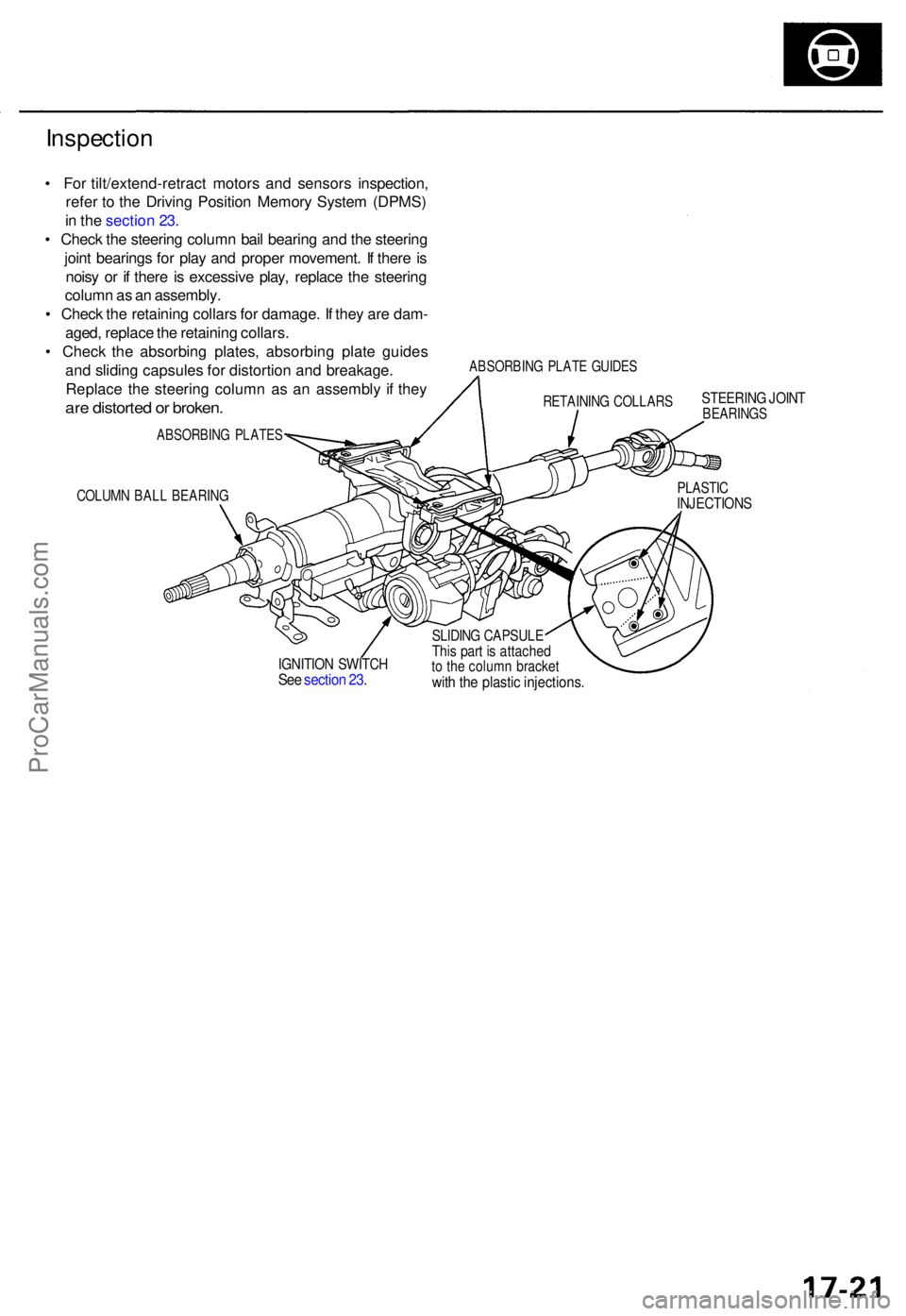
• Fo r tilt/extend-retrac t motor s an d sensor s inspection ,
refe r t o th e Drivin g Positio n Memor y Syste m (DPMS )
i n th e sectio n 23 .
• Chec k th e steerin g colum n bai l bearin g an d th e steerin g
join t bearing s fo r pla y an d prope r movement . I f ther e is
nois y o r i f ther e is excessiv e play , replac e th e steerin g
colum n a s a n assembly .
• Chec k th e retainin g collar s fo r damage . I f the y ar e dam -
aged , replac e th e retainin g collars .
• Chec k th e absorbin g plates , absorbin g plat e guide s
an d slidin g capsule s fo r distortio n an d breakage .
Replac e th e steerin g colum n a s a n assembl y i f the y
are distorte d o r broken .
ABSORBIN G PLATE S
COLUMN BAL L BEARIN G
ABSORBIN G PLAT E GUIDE S
STEERIN G JOIN TBEARING S
PLASTICINJECTION S
IGNITION SWITC HSee sectio n 23 .
SLIDIN G CAPSUL EThis par t i s attache dto th e colum n bracke twith th e plasti c injections .
RETAININ G COLLAR S
ProCarManuals.com
Page 1000 of 1954
Power Steering Gearbox
Removal (cont'd)
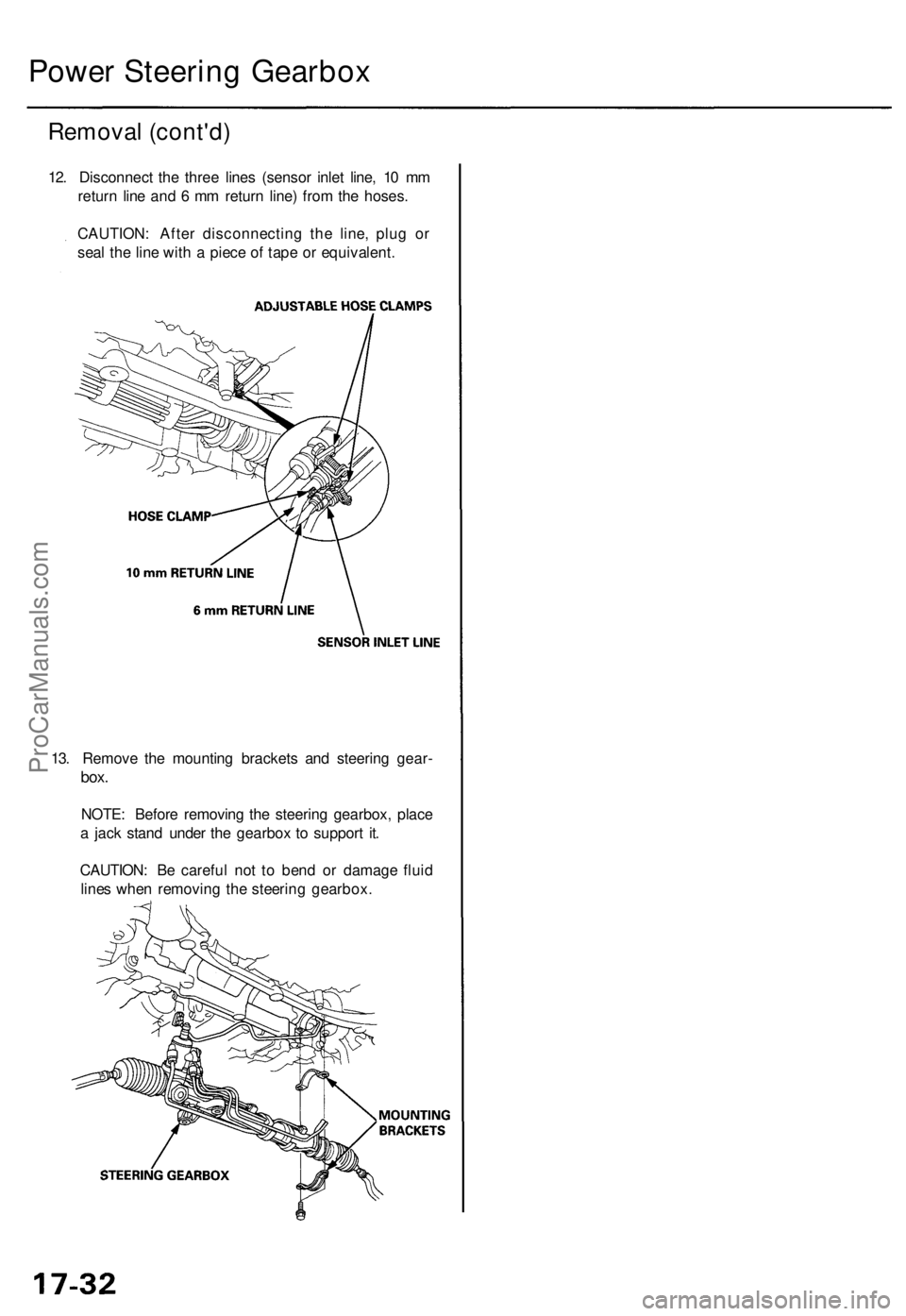
12. Disconnect the three lines (sensor inlet line, 10 mm
return line and 6 mm return line) from the hoses.
CAUTION: After disconnecting the line, plug or
seal the line with a piece of tape or equivalent.
13. Remove the mounting brackets and steering gear-
box.
NOTE: Before removing the steering gearbox, place
a jack stand under the gearbox to support it.
CAUTION: Be careful not to bend or damage fluid
lines when removing the steering gearbox.ProCarManuals.com