Filter ACURA RL KA9 1996 Service User Guide
[x] Cancel search | Manufacturer: ACURA, Model Year: 1996, Model line: RL KA9, Model: ACURA RL KA9 1996Pages: 1954, PDF Size: 61.44 MB
Page 626 of 1954
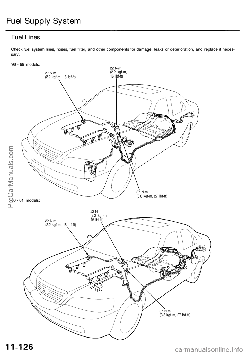
Fuel Supply System
Fuel Lines
Check fuel system lines, hoses, fuel filter, and other components for damage, leaks or deterioration, and replace if neces-
sary.
'96 - 99 models:
22 N-m
(2.2 kgf-m, 16 Ibf-ft)
22 N-m
(2.2 kgf-m,
16 Ibf-ft)
'00 - 01 models:
37 N-m
(3.8 kgf-m, 27 Ibf-ft)
22 N-m
(2.2 kgf-m, 16 Ibf-ft)
22 N-m
(2.2 kgf-m
16 Ibf-ft)
37 N-m
(3.8 kgf-m, 27 Ibf-ft)ProCarManuals.com
Page 627 of 1954
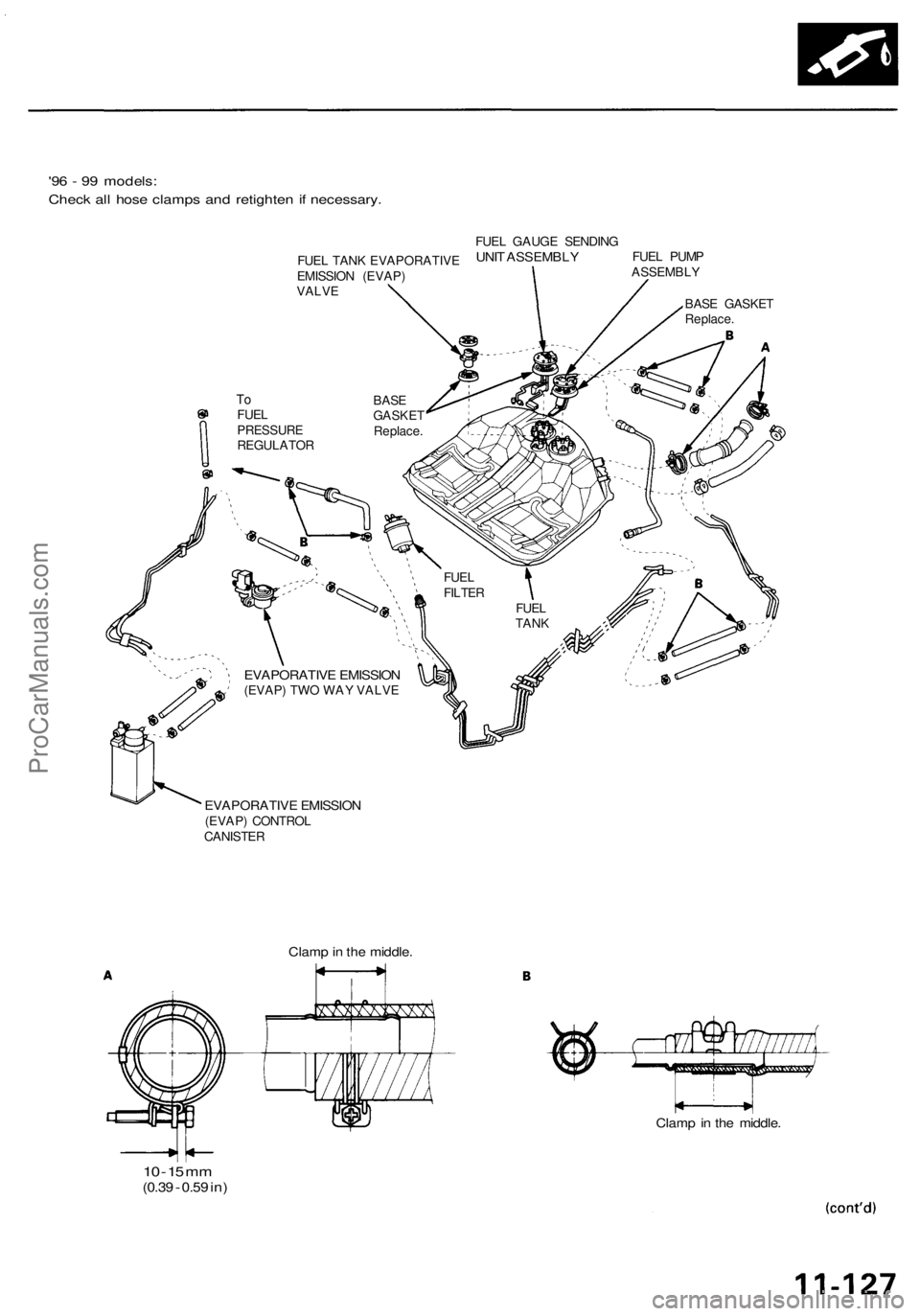
'96 - 99 models:
Check all hose clamps and retighten if necessary.
EVAPORATIVE EMISSION
(EVAP) TWO WAY VALVE
EVAPORATIVE EMISSION
(EVAP) CONTROL
CANISTER
10 -
15
mm
(0.39
-
0.59
in)
Clamp in the middle.
Clamp in the middle.
FUEL
TANK
FUEL
FILTER
To
FUEL
PRESSURE
REGULATOR
BASE
GASKET
Replace.
BASE GASKET
Replace.
FUEL PUMP
ASSEMBLY
FUEL GAUGE SENDING
UNIT ASSEMBLY
FUEL TANK EVAPORATIVE
EMISSION (EVAP)
VALVEProCarManuals.com
Page 628 of 1954
Fuel Supply System
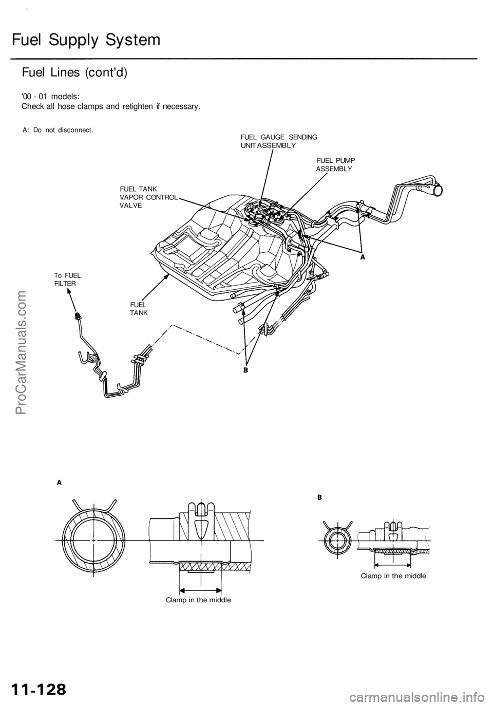
Fuel Lines (cont'd)
'00 - 01 models:
Check all hose clamps and retighten if necessary.
A: Do not disconnect.
To FUEL
FILTER
FUEL TANK
VAPOR CONTROL
VALVE
FUEL GAUGE SENDING
UNIT ASSEMBLY
Clamp in the middle
Clamp in the middle
FUEL
TANK
FUEL PUMP
ASSEMBLYProCarManuals.com
Page 632 of 1954
Fuel Suppl y Syste m
System Descriptio n
The fue l suppl y syste m consist s o f a fue l tank , in-tan k
high-pressur e fue l pump , PGM-F I mai n relay , fue l filter ,
fue l pressur e regulator , fue l pressur e regulato r contro l
solenoi d valve , injectors , an d fue l deliver y an d retur n
lines . Thi s syste m deliver s pressure-regulate d fue l t o th e
injector s an d cut s th e fue l deliver y whe n th e engin e i s
no t running .
Fuel Pressur e
Relieving
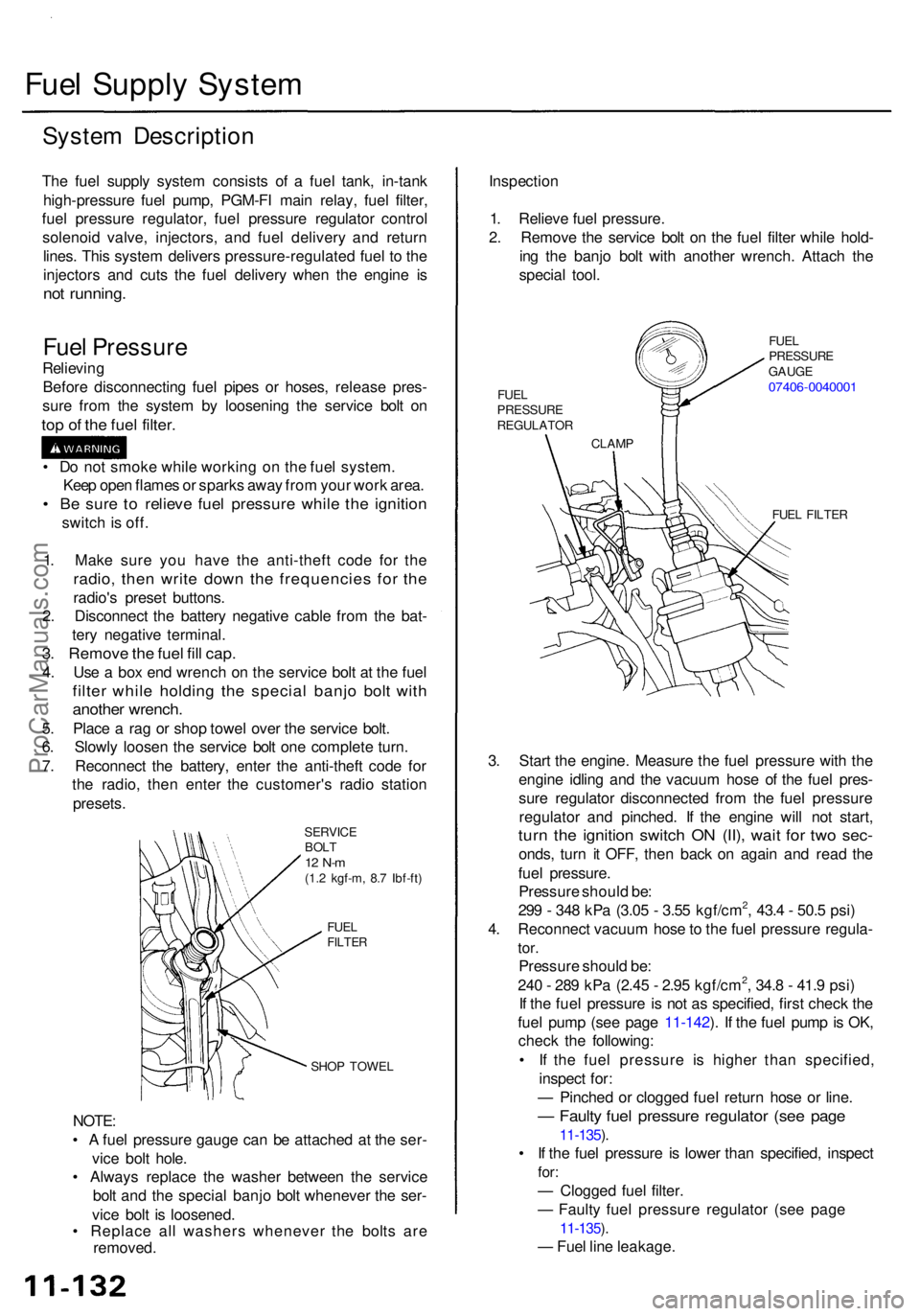
Befor e disconnectin g fue l pipe s o r hoses , releas e pres -
sur e fro m th e syste m b y loosenin g th e servic e bol t o n
top o f th e fue l filter .
SERVIC E
BOL T
12 N- m(1.2 kgf-m , 8. 7 Ibf-ft )
FUE L
FILTE R
SHOP TOWE L
NOTE:
• A fue l pressur e gaug e can be attache d a t th e ser -
vic e bol t hole .
• Alway s replac e th e washe r betwee n th e servic e
bol t an d th e specia l banj o bol t wheneve r th e ser -
vic e bol t i s loosened .
• Replac e al l washer s wheneve r th e bolt s ar e
removed . Inspectio
n
1 . Reliev e fue l pressure .
2 . Remov e th e servic e bol t o n th e fue l filte r whil e hold -
in g th e banj o bol t wit h anothe r wrench . Attac h th e
specia l tool .
FUEL FILTE R
3. Star t th e engine . Measur e th e fue l pressur e wit h th e
engin e idlin g an d th e vacuu m hos e o f th e fue l pres -
sur e regulato r disconnecte d fro m th e fue l pressur e
regulato r an d pinched . I f th e engin e wil l no t start ,
turn th e ignitio n switc h O N (II) , wai t fo r tw o sec -
onds , tur n i t OFF , the n bac k o n agai n an d rea d th e
fue l pressure .
Pressur e shoul d be :
29 9 - 34 8 kP a (3.0 5 - 3.5 5 kgf/cm
2, 43. 4 - 50. 5 psi )
4 . Reconnec t vacuu m hos e to th e fue l pressur e regula -
tor.
Pressur e shoul d be :
24 0 - 28 9 kP a (2.4 5 - 2.9 5 kgf/cm2, 34. 8 - 41. 9 psi )
I f th e fue l pressur e i s no t a s specified , firs t chec k th e
fue l pum p (se e pag e 11-142 ). I f th e fue l pum p is OK ,
chec k th e following :
• I f th e fue l pressur e i s highe r tha n specified ,
inspec t for :
— Pinche d o r clogge d fue l retur n hos e o r line .
— Fault y fue l pressur e regulato r (se e pag e
11-135 ).
• I f th e fue l pressur e i s lowe r tha n specified , inspec t
for:
— Clogge d fue l filter .
— Fault y fue l pressur e regulato r (se e pag e
11-135 ).
— Fue l lin e leakage .
1
. Mak e sur e yo u hav e th e anti-thef t cod e fo r th e
radio , the n writ e dow n th e frequencie s fo r th e
radio' s prese t buttons .
2 . Disconnec t th e batter y negativ e cabl e fro m th e bat -
ter y negativ e terminal .
3. Remov e th e fue l fil l cap .
4. Us e a bo x en d wrenc h o n th e servic e bol t a t th e fue l
filte r whil e holdin g th e specia l banj o bol t wit h
anothe r wrench .
5. Plac e a ra g o r sho p towe l ove r th e servic e bolt .
6 . Slowl y loose n th e servic e bol t on e complet e turn .
7 . Reconnec t th e battery , ente r th e anti-thef t cod e fo r
th e radio , the n ente r th e customer' s radi o statio n
presets .
•
D o no t smok e whil e workin g o n th e fue l system .
Kee p ope n flame s o r spark s awa y fro m you r wor k area .
• B e sur e t o reliev e fue l pressur e whil e th e ignitio n
switch is off .
CLAM P
FUE
L
PRESSUR E
REGULATO R FUE
L
PRESSUR E
GAUG E
07406-004000 1
ProCarManuals.com
Page 642 of 1954
Fuel Suppl y Syste m
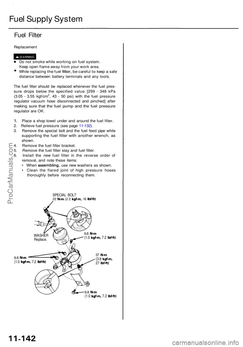
Fuel Filte r
Replacemen t
D o no t smok e whil e workin g o n fue l system .
Kee p ope n flam e awa y fro m you r wor k area .
• Whil e replacin g the fue l filter , be carefu l to kee p a safe
distanc e betwee n batter y terminal s an d an y tools .
Th e fue l filte r shoul d b e replace d wheneve r th e fue l pres -
sur e drop s belo w th e specifie d valu e [29 9 - 34 8 kP a
(3.0 5 - 3.5 5
kgf/cm2, 43 - 5 0 psi ) wit h th e fue l pressur e
regulato r vacuu m hos e disconnecte d an d pinched ] afte r
makin g sur e tha t th e fue l pum p an d th e fue l pressur e
regulator ar e OK .
1. Plac e a sho p towe l unde r an d aroun d th e fue l filter .
2 . Reliev e fue l pressur e (se e pag e 11-132 ).
3 . Remov e th e specia l bol t an d th e fue l fee d pip e whil e
supportin g th e fue l filte r wit h anothe r wrench , a s
shown .
4 . Remov e th e fue l filte r bracket .
5 . Remov e th e fue l filte r sta y an d fue l filter .
6 . Instal l th e ne w fue l filte r i n th e revers e orde r of
removal , an d not e thes e items :
• Whe n assembling , use ne w washer s a s shown .
• Clea n th e flare d join t o f hig h pressur e hose s
thoroughl y befor e reconnectin g them .
SPECIA L BOL T22 N- m (2. 2 kgf-m , 16 Ibf-ft )
9.8 N- m(1.0 kgf-m , 7.2 Ibf-ft )
9.8 N- m(1.0 kgf-m , 7.2 Ibf-ft )
37 N- m(3.8 kgf-m ,27 Ibf-ft )
9.8 N- m(1.0 kgf-m , 7.2 Ibf-ft )
WASHE R
Replace .
ProCarManuals.com
Page 680 of 1954
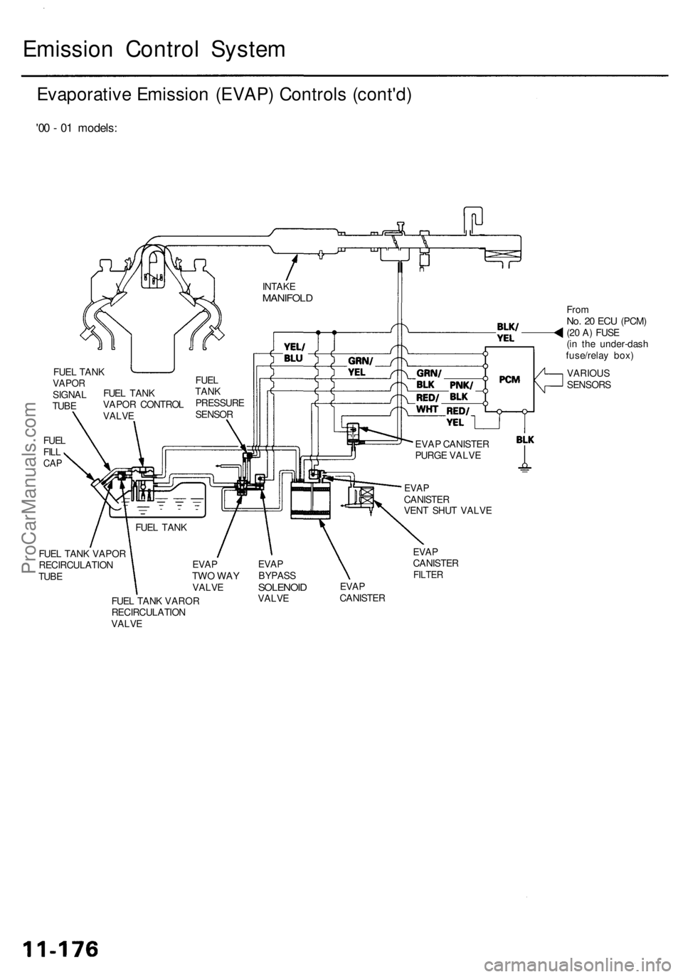
Emission Control System
Evaporative Emission (EVAP) Controls (cont'd)
'00 - 01 models:
From
No. 20 ECU
(PCM)
(20 A) FUSE
(in the under-dash
fuse/relay box)
FUEL TANK VAPOR
RECIRCULATION
TUBE
EVAP
BYPASS
SOLENOID
VALVE
EVAP
CANISTER
FILTER
EVAP
CANISTER
FUEL TANK VAROR
RECIRCULATION
VALVE
EVAP
TWO WAY
VALVE
FUEL TANK
EVAP
CANISTER
VENT SHUT VALVE
EVAP CANISTER
PURGE VALVE
VARIOUS
SENSORS
INTAKE
MANIFOLD
FUEL
TANK
PRESSURE
SENSOR
FUEL TANK
VAPOR CONTROL
VALVE
FUEL
FILL
CAP
FUEL TANK
VAPOR
SIGNAL
TUBEProCarManuals.com
Page 794 of 1954
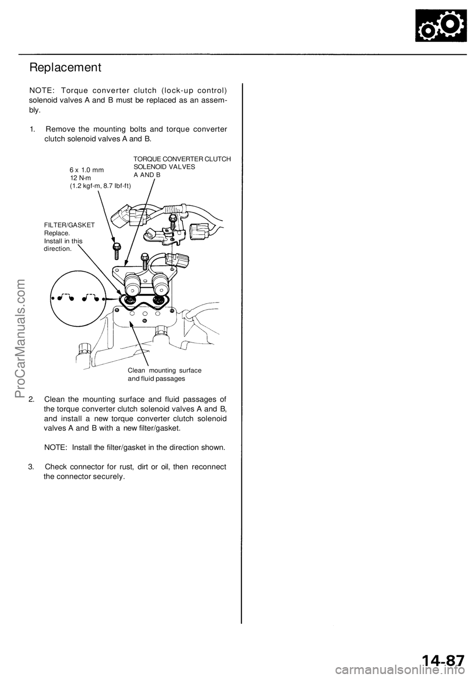
Replacement
NOTE: Torque converter clutch (lock-up control)
solenoid valves A and B must be replaced as an assem-
bly.
1. Remove the mounting bolts and torque converter
clutch solenoid valves A and B.
6 x 1.0 mm
12 N-m
(1.2 kgf-m, 8.7 Ibf-ft)
TORQUE CONVERTER CLUTCH
SOLENOID VALVES
A AND B
FILTER/GASKET
Replace.
Install in this
direction.
Clean mounting surface
and fluid passages
2. Clean the mounting surface and fluid passages of
the torque converter clutch solenoid valves A and B,
and install a new torque converter clutch solenoid
valves A and B with a new filter/gasket.
NOTE: Install the filter/gasket in the direction shown.
3. Check connector for rust, dirt or oil, then reconnect
the connector securely.ProCarManuals.com
Page 820 of 1954
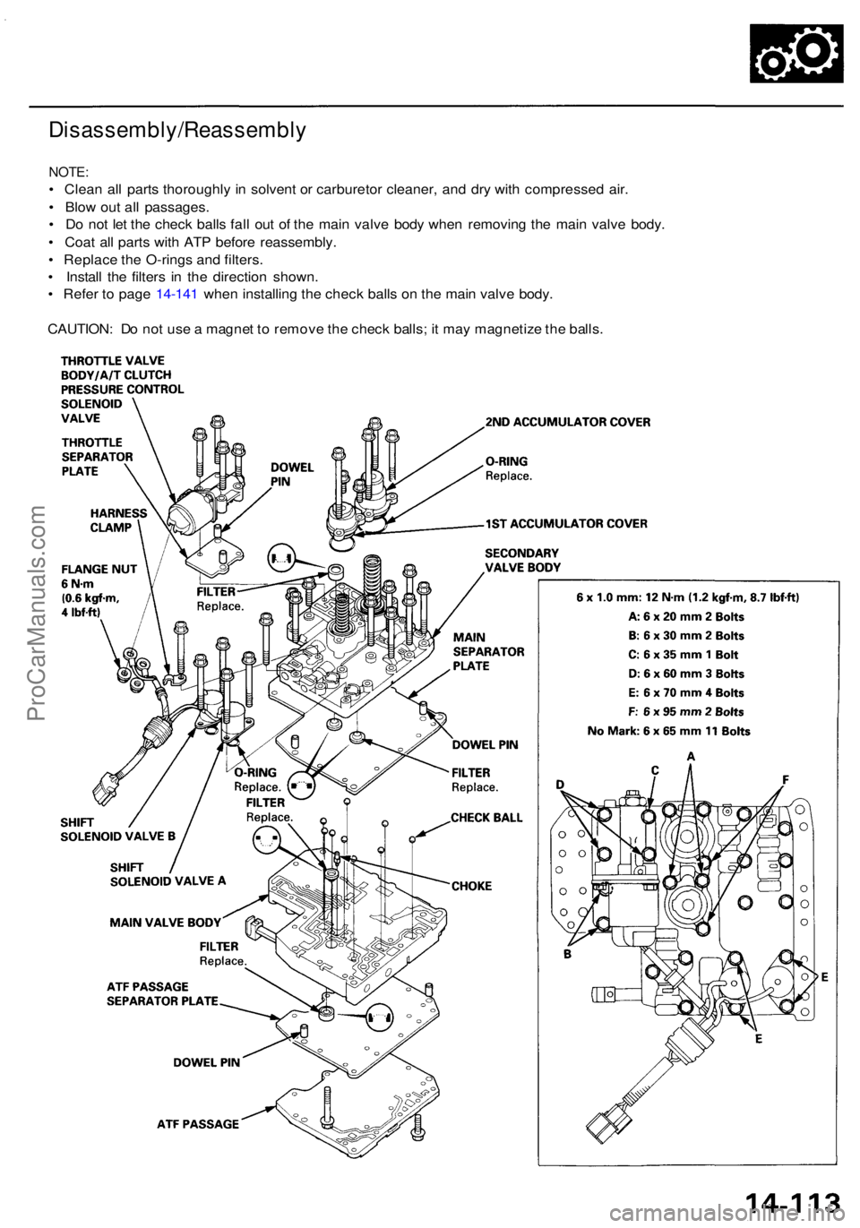
Disassembly/Reassembly
NOTE:
• Clea n al l part s thoroughl y i n solven t o r carbureto r cleaner , an d dr y wit h compresse d air .
• Blo w ou t al l passages .
• D o no t le t th e chec k ball s fal l ou t o f th e mai n valv e bod y whe n removin g th e mai n valv e body .
• Coa t al l part s wit h AT P befor e reassembly .
• Replac e th e O-ring s an d filters .
• Instal l th e filter s i n th e directio n shown .
• Refe r t o pag e 14-14 1 whe n installin g th e chec k ball s o n th e mai n valv e body .
CAUTION : D o no t us e a magne t t o remov e th e chec k balls ; i t ma y magnetiz e th e balls .
ProCarManuals.com
Page 828 of 1954
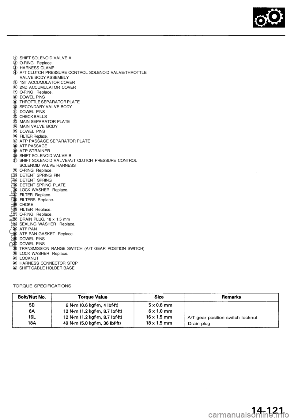
SHIFT SOLENOI D VALV E A
O-RIN G Replace .
HARNES S CLAM P
A/ T CLUTC H PRESSUR E CONTRO L SOLENOI D VALVE/THROTTL E
VALV E BOD Y ASSEMBL Y
1S T ACCUMULATO R COVE R
2N D ACCUMULATO R COVE R
O-RIN G Replace .
DOWEL PIN STHROTTL E SEPARATO R PLAT E
SECONDAR Y VALV E BOD Y
DOWE L PIN S
CHEC K BALL S
MAI N SEPARATO R PLAT E
MAI N VALV E BOD Y
DOWE L PIN S
FILTE R Replace.
ATP PASSAGE SEPARATOR PLATE
ATF PASSAGEATP STRAINER
SHIF T SOLENOI D VALV E B
SHIF T SOLENOI D VALVE/A/ T CLUTC H PRESSUR E CONTRO L
SOLENOI D VALV E HARNES S
O-RIN G Replace .
DETEN T SPRIN G PI N
DETEN T SPRIN G
DETEN T SPRIN G PLAT E
LOC K WASHE R Replace .
FILTE R Replace .
FILTER S Replace .
CHOKEFILTER Replace .
O-RIN G Replace .
DRAI N PLUG , 1 8 x 1. 5 m m
SEALIN G WASHE R Replace .
ATF PA NATF PA N GASKE T Replace .
DOWE L PIN S
DOWE L PIN S
TRANSMISSIO N RANG E SWITC H (A/ T GEA R POSITIO N SWITCH )
LOC K WASHE R Replace .
LOCKNU T
HARNES S CONNECTO R STO P
SHIF T CABL E HOLDE R BAS E
TORQU E SPECIFICATION S
A/T gea r positio n switc h locknu t
Drain plu g
ProCarManuals.com
Page 834 of 1954
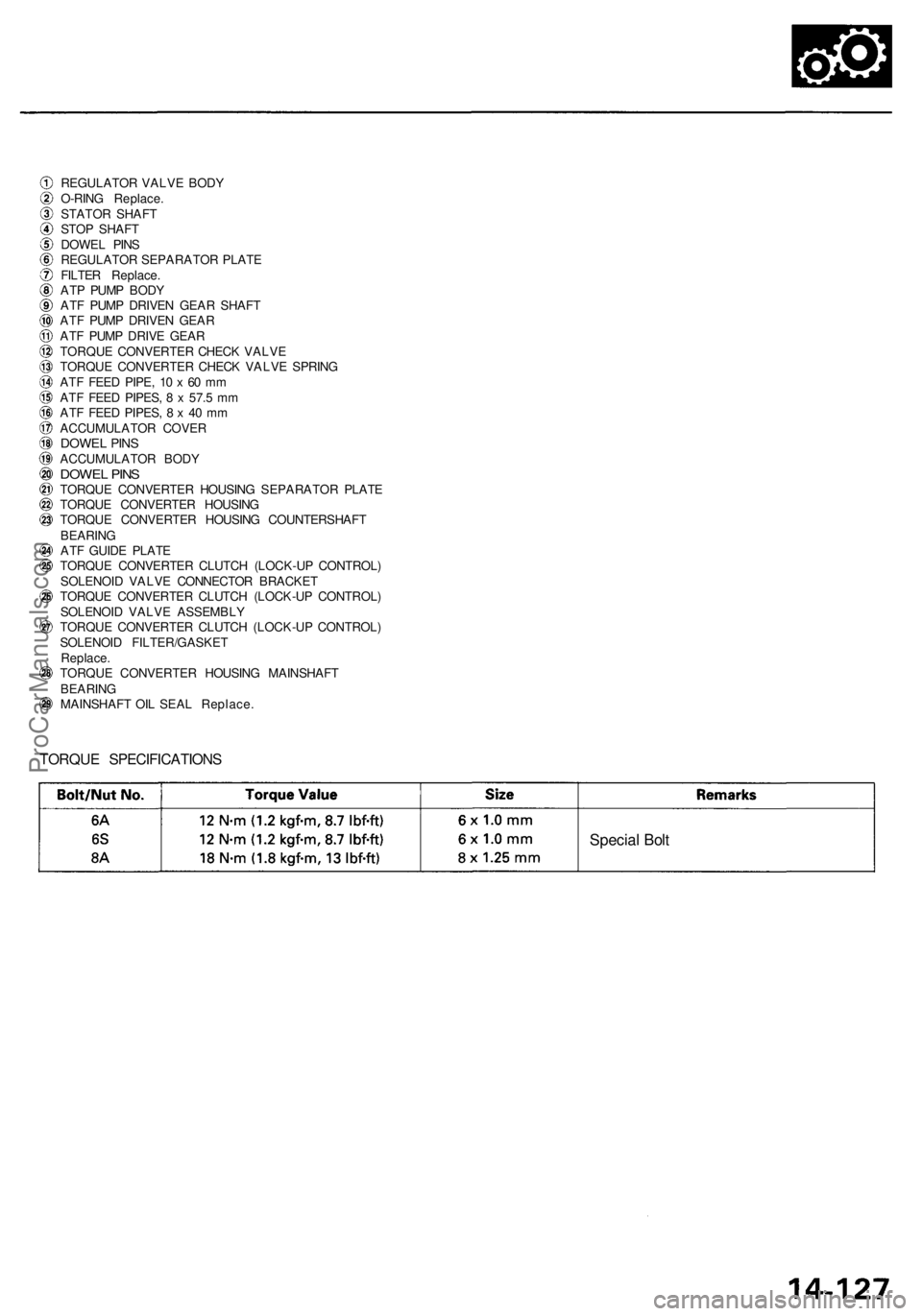
REGULATOR VALV E BOD Y
O-RIN G Replace .
STATO R SHAF T
STO P SHAF T
DOWE L PIN S
REGULATO R SEPARATO R PLAT E
FILTE R Replace .
AT P PUM P BOD Y
AT F PUM P DRIVE N GEA R SHAF T
AT F PUM P DRIVE N GEA R
AT F PUM P DRIV E GEA R
TORQU E CONVERTE R CHEC K VALV E
TORQU E CONVERTE R CHEC K VALV E SPRIN G
AT F FEE D PIPE , 1 0 x 60 m m
AT F FEE D PIPES , 8 x 57. 5 m m
AT F FEE D PIPES , 8 x 4 0 m m
ACCUMULATO R COVE R
DOWEL PIN SACCUMULATO R BOD YDOWE L PIN STORQU E CONVERTE R HOUSIN G SEPARATO R PLAT E
TORQU E CONVERTE R HOUSIN G
TORQU E CONVERTE R HOUSIN G COUNTERSHAF T
BEARIN G
AT F GUID E PLAT E
TORQU E CONVERTE R CLUTC H (LOCK-U P CONTROL )
SOLENOI D VALV E CONNECTO R BRACKE T
TORQU E CONVERTE R CLUTC H (LOCK-U P CONTROL )
SOLENOI D VALV E ASSEMBL Y
TORQU E CONVERTE R CLUTC H (LOCK-U P CONTROL )
SOLENOI D FILTER/GASKE T
Replace .
TORQU E CONVERTE R HOUSIN G MAINSHAF T
BEARIN G
MAINSHAF T OI L SEA L Replace .
TORQUE SPECIFICATION S
Special Bol t
ProCarManuals.com