alternator ACURA RL KA9 1996 Service Repair Manual
[x] Cancel search | Manufacturer: ACURA, Model Year: 1996, Model line: RL KA9, Model: ACURA RL KA9 1996Pages: 1954, PDF Size: 61.44 MB
Page 343 of 1954
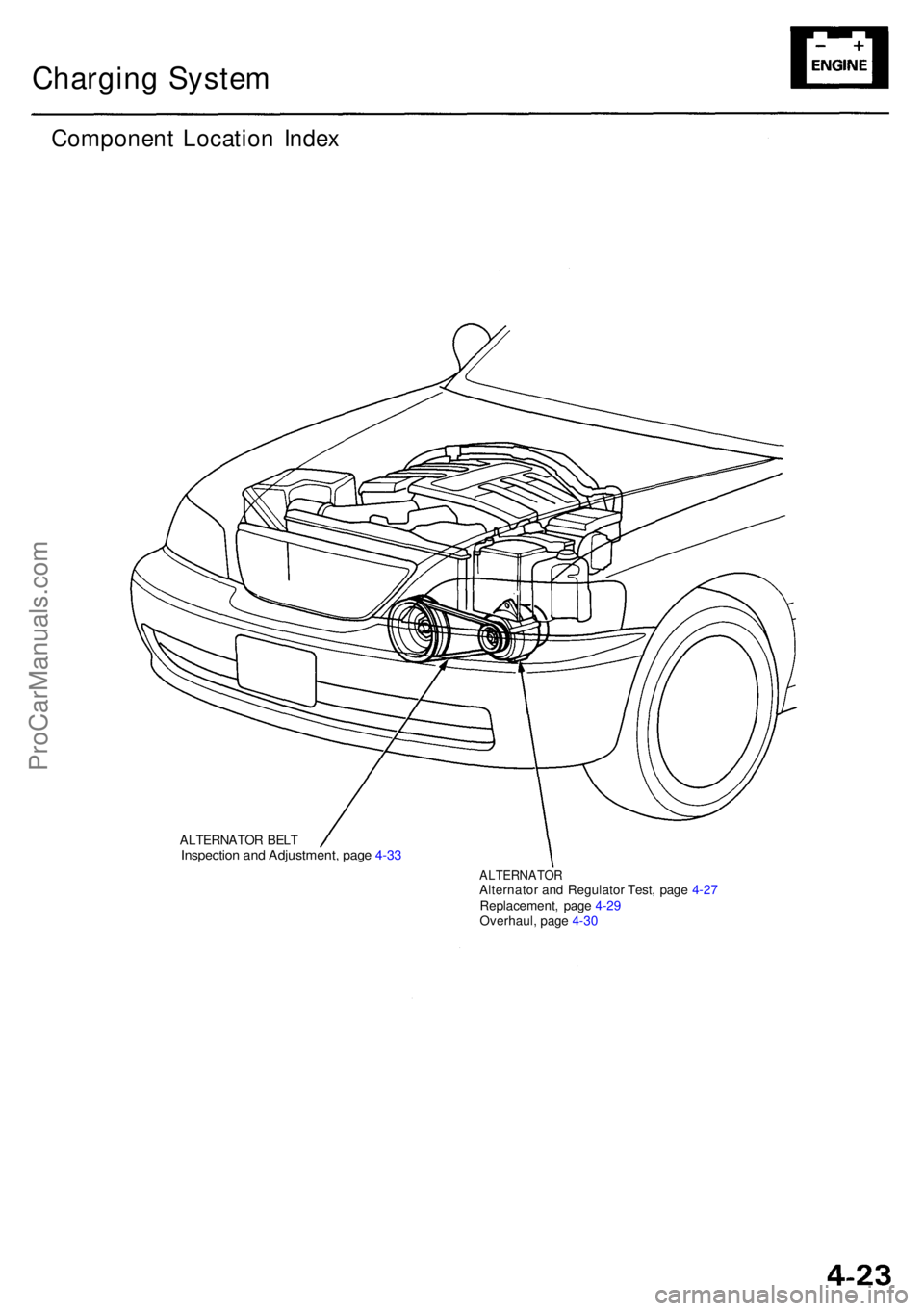
Charging Syste m
Componen t Locatio n Inde x
ALTERNATO R BEL TInspectio n an d Adjustment , pag e 4-3 3
ALTERNATO RAlternator an d Regulato r Test , pag e 4-2 7
Replacement , pag e 4-2 9
Overhaul , pag e 4-3 0
ProCarManuals.com
Page 344 of 1954
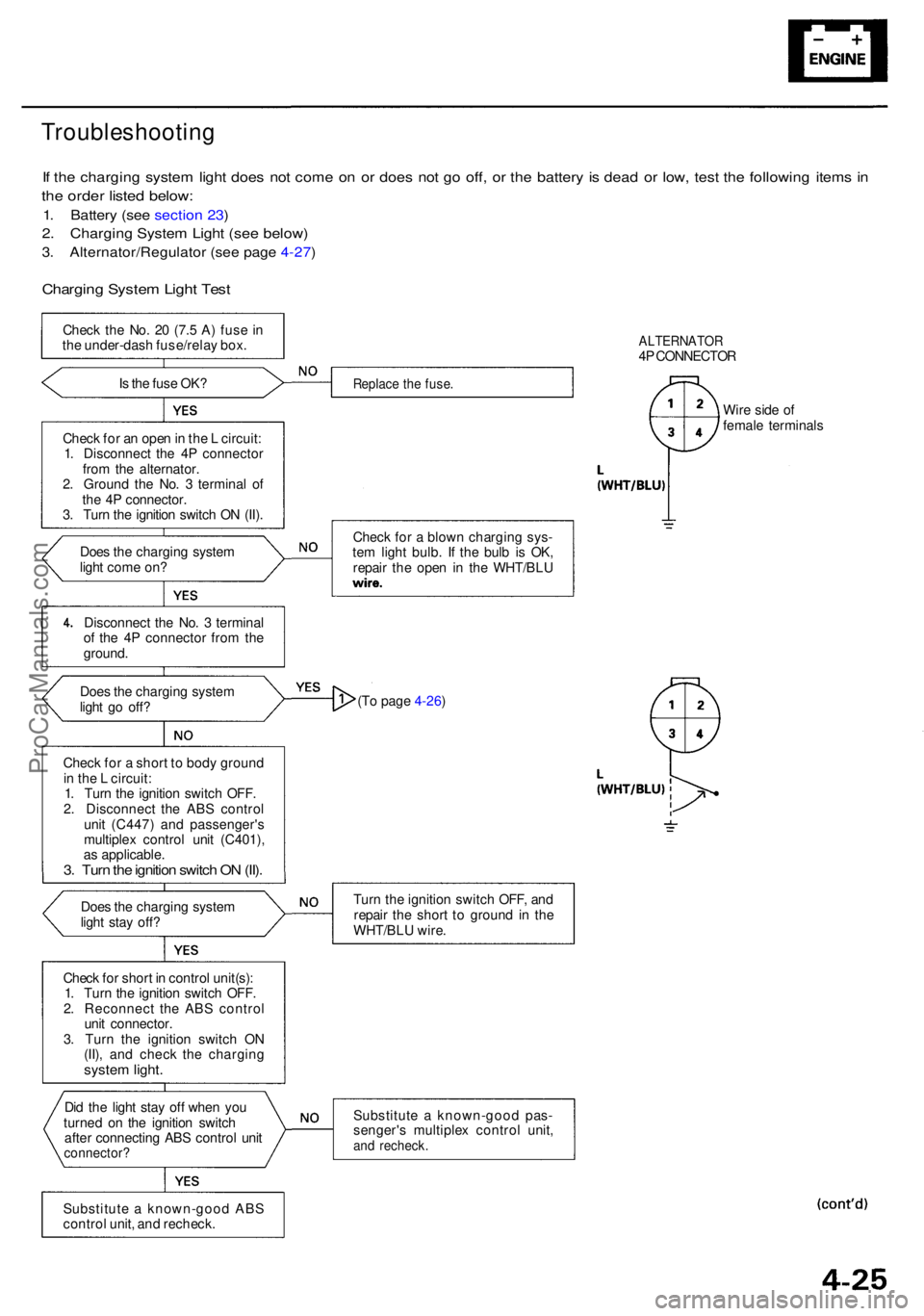
Troubleshooting
If th e chargin g syste m ligh t doe s no t com e o n o r doe s no t g o off , o r th e batter y i s dea d o r low , tes t th e followin g item s i n
th e orde r liste d below :
1. Batter y (se e sectio n 23 )
2. Chargin g Syste m Ligh t (se e below )
3. Alternator/Regulato r (se e pag e 4-27 )
Chargin g Syste m Ligh t Tes t
Chec k th e No . 2 0 (7. 5 A ) fus e i n
th e under-das h fuse/rela y box .
I s th e fus e OK ?
Chec k fo r a n ope n in th e L circuit :
1 . Disconnec t th e 4 P connecto r
fro m th e alternator .
2 . Groun d th e No . 3 termina l o f
th e 4 P connector .
3 . Tur n th e ignitio n switc h O N (II) .
Doe s th e chargin g syste m
ligh t com e on ?
Disconnec t th e No . 3 termina l
o f th e 4 P connecto r fro m th e
ground .
Doe s th e chargin g syste m
ligh t g o off ?
Chec k fo r a shor t t o bod y groun d
i n th e L circuit :
1 . Tur n th e ignitio n switc h OFF .
2 . Disconnec t th e AB S contro l
uni t (C447 ) an d passenger' s
multiple x contro l uni t (C401) ,
a s applicable .
3. Tur n th e ignitio n switc h O N (II) .
Doe s th e chargin g syste m
ligh t sta y off ?
Chec k fo r shor t i n contro l unit(s) :
1 . Tur n th e ignitio n switc h OFF .
2 . Reconnec t th e AB S contro l
uni t connector .
3 . Tur n th e ignitio n switc h O N
(II) , an d chec k th e chargin g
system light .
Did th e ligh t sta y of f whe n yo u
turne d o n th e ignitio n switc h
afte r connectin g AB S contro l uni t
connector ?
Substitute a known-goo d AB S
contro l unit , an d recheck .
ALTERNATO R4P CONNECTO R
Replace th e fuse .
Chec k fo r a blow n chargin g sys -
te m ligh t bulb . I f th e bul b i s OK ,
repai r th e ope n i n th e WHT/BL U Wir
e sid e o f
femal e terminal s
(T o page 4-26)
Tur n th e ignitio n switc h OFF , an d
repai r th e shor t t o groun d in th e
WHT/BL U wire .
Substitut e a known-goo d pas -
senger' s multiple x contro l unit ,
and recheck .
ProCarManuals.com
Page 345 of 1954
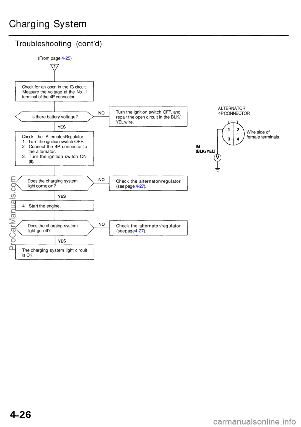
Charging Syste m
Troubleshootin g (cont'd )
(From page 4-25)
Chec k fo r a n ope n in th e IG circuit :
Measur e th e voltag e a t th e No . 1
termina l o f th e 4 P connector .
I s ther e batter y voltage ?
Chec k th e Alternator/Regulator :
1. Tur n th e ignitio n switc h OFF .2. Connec t th e 4 P connecto r t o
th e alternator .
3. Tur n th e ignitio n switc h O N(II).
Doe s th e chargin g syste mlight com e on ?
4. Star t th e engine .
Doe s th e chargin g syste m
ligh t g o off ?
Th e chargin g syste m ligh t circui t
is OK .
Turn th e ignitio n switc h OFF , an drepai r th e ope n circui t i n th e BLK /YEL wire .
ALTERNATO R4P CONNECTO R
Wir e sid e o f
femal e terminal s
Check th e alternator/regulato r
(se e pag e 4-27 ).
Chec k th e alternator/regulato r
(se e pag e 4-27 ).
ProCarManuals.com
Page 346 of 1954
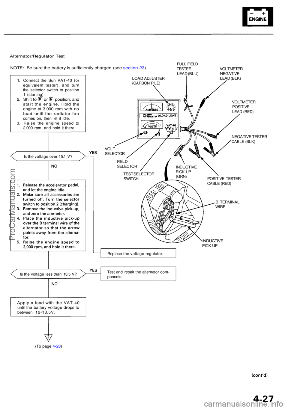
Alternator/Regulator Tes t
NOTE : B e sur e th e batter y is sufficientl y charge d (se e sectio n 23 ).
1 . Connec t th e Sun VAT-4 0 (o r
equivalen t tester) , an d tur n
th e selecto r switc h t o positio n
1 (starting) .
2. Shif t t o o r position , an dstar t th e engine . Hol d th eengin e a t 3,00 0 rp m wit h n oloa d unti l th e radiato r fa ncome s on , the n le t i t idle .
3 . Rais e th e engin e spee d t o
2,00 0 rpm , an d hol d i t there .
I s th e voltag e ove r 15. 1 V ?
I s th e voltag e les s tha n 13. 5 V ?
Appl y a loa d wit h th e VAT-4 0until th e batter y voltag e drop s t obetwee n 12-13.5V . FUL
L FIEL D
TESTE R
LEA D (BLU )
LOA D ADJUSTE R
(CARBON PILE )
VOLTMETE R
NEGATIV E
LEAD (BLK )
VOLTSELECTO R
VOLTMETE R
POSITIV E
LEAD (RED )
NEGATIV E TESTE RCABLE (BLK )
FIELDSELECTO R
TEST SELECTO R
SWITC H POSITIV
E TESTE R
CABLE (RED )
B TERMINA LWIRE
INDUCTIV EPICK-UP
Replac e th e voltag e regulator .
Tes t an d repai r th e alternato r com -
ponents .
(T o page 4-28)
INDUCTIV EPICK-UP(GRN)
ProCarManuals.com
Page 347 of 1954
Charging Syste m
Troubleshootin g (cont'd )
(From page 4-27)
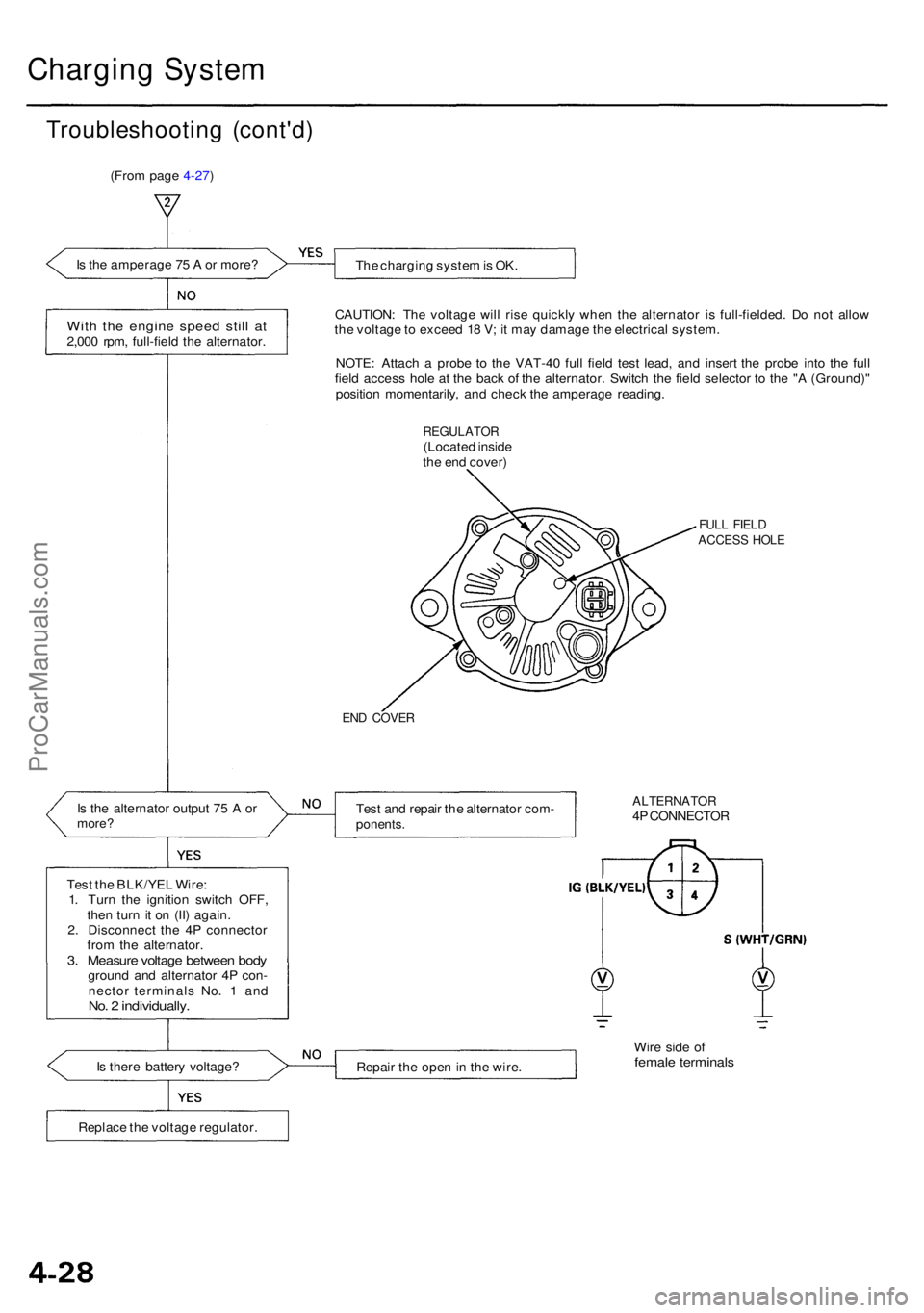
I s th e amperag e 7 5 A or more ?
The chargin g syste m is OK .
Wit h th e engin e spee d stil l a t2,00 0 rpm , full-fiel d th e alternator. CAUTION
: Th e voltag e wil l ris e quickl y whe n th e alternato r i s full-fielded . D o no t allo w
th e voltag e to excee d 1 8 V ; i t ma y damag e th e electrica l system .
NOTE : Attac h a prob e t o th e VAT-4 0 ful l fiel d tes t lead , an d inser t th e prob e int o th e ful l
fiel d acces s hol e a t th e bac k o f th e alternator . Switc h th e fiel d selecto r t o th e " A (Ground) "
positio n momentarily , an d chec k th e amperag e reading .
REGULATO R(Located insid e
th e en d cover )
FULL FIEL DACCES S HOL E
END COVE R
Is th e alternato r outpu t 7 5 A ormore ?Test an d repai r th e alternato r com -ponents .
ALTERNATO R4P CONNECTO R
Tes t th e BLK/YE L Wire :
1 . Tur n th e ignitio n switc h OFF ,
the n tur n i t o n (II ) again .
2 . Disconnec t th e 4 P connecto r
fro m th e alternator .
3. Measur e voltag e betwee n bod ygroun d an d alternato r 4 P con -
necto r terminal s No . 1 an d
No. 2 individually .
Is ther e batter y voltage ?
Repair th e ope n in th e wire . Wir
e sid e o ffemal e terminal s
Replace th e voltag e regulator .
ProCarManuals.com
Page 348 of 1954
Alternator Replacemen t
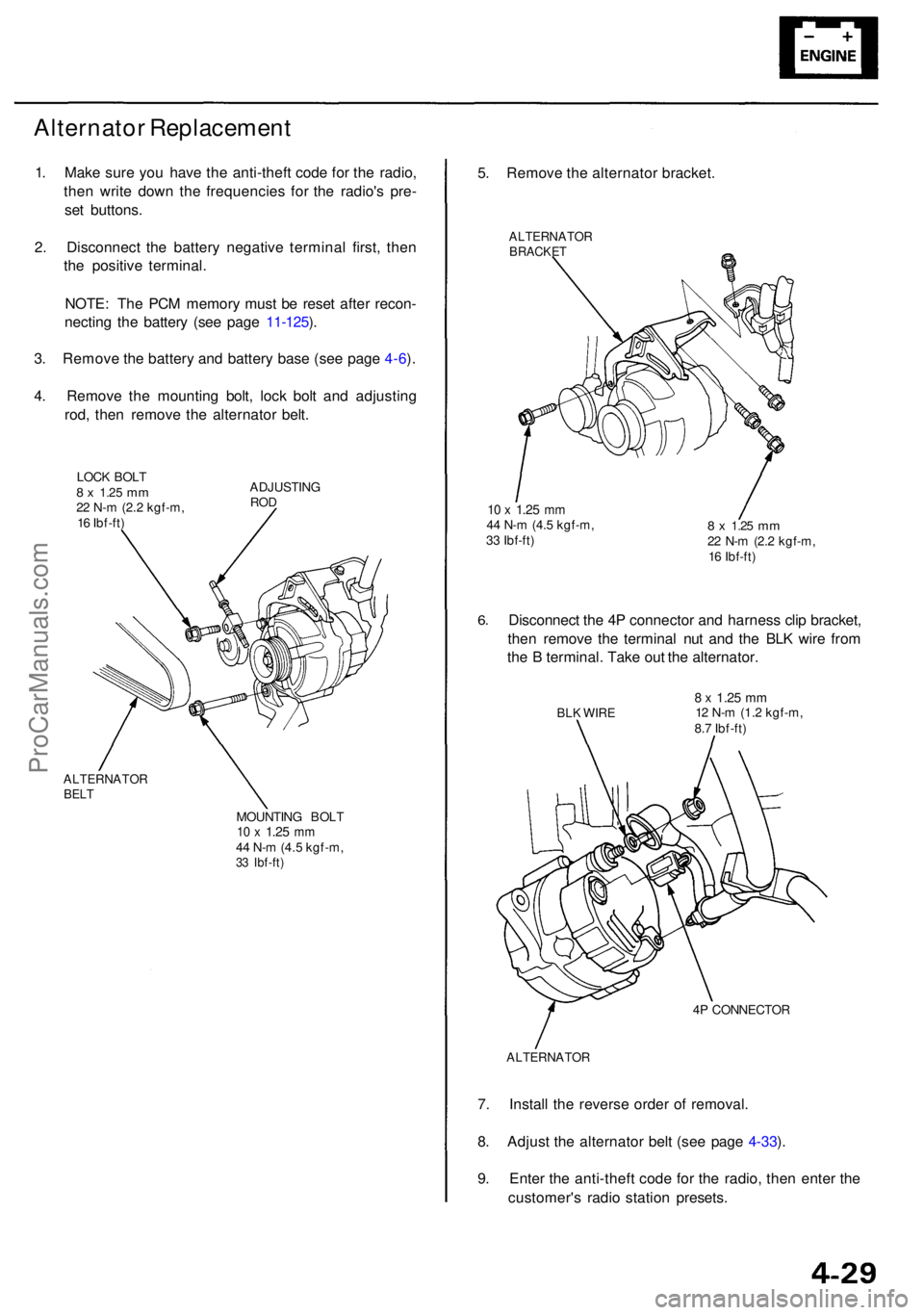
1. Mak e sur e yo u hav e th e anti-thef t cod e fo r th e radio ,
the n writ e dow n th e frequencie s fo r th e radio' s pre -
se t buttons .
2 . Disconnec t th e batter y negativ e termina l first , the n
th e positiv e terminal .
NOTE : Th e PC M memor y mus t b e rese t afte r recon -
nectin g th e batter y (se e pag e 11-125 ).
3 . Remov e th e batter y an d batter y bas e (se e pag e 4-6 ).
4 . Remov e th e mountin g bolt , loc k bol t an d adjustin g
rod , the n remov e th e alternato r belt .
LOC K BOL T8 x 1.2 5 mm22 N- m (2. 2 kgf-m ,
1 6 Ibf-ft ) ADJUSTIN
GROD
ALTERNATO RBELT
MOUNTIN G BOL T10 x 1.2 5 mm44 N- m (4. 5 kgf-m ,33 Ibf-ft )
5. Remov e th e alternato r bracket .
ALTERNATO RBRACKET
10 x 1.2 5 mm44 N- m (4. 5 kgf-m ,
3 3 Ibf-ft )8 x 1.2 5 mm22 N- m (2. 2 kgf-m ,
1 6 Ibf-ft )
6.Disconnec t th e 4 P connecto r an d harnes s cli p bracket ,
the n remov e th e termina l nu t an d th e BL K wir e fro m
th e B terminal . Tak e ou t th e alternator .
BLK WIR E8 x 1.2 5 mm12 N- m (1.2 kgf-m ,
8. 7 Ibf-ft )
4 P CONNECTO R
ALTERNATO R
7. Instal l th e revers e orde r o f removal .
8 . Adjus t th e alternato r bel t (se e pag e 4-33 ).
9 . Ente r th e anti-thef t cod e fo r th e radio , the n ente r th e
customer' s radi o statio n presets .
ProCarManuals.com
Page 350 of 1954
Rectifier Test
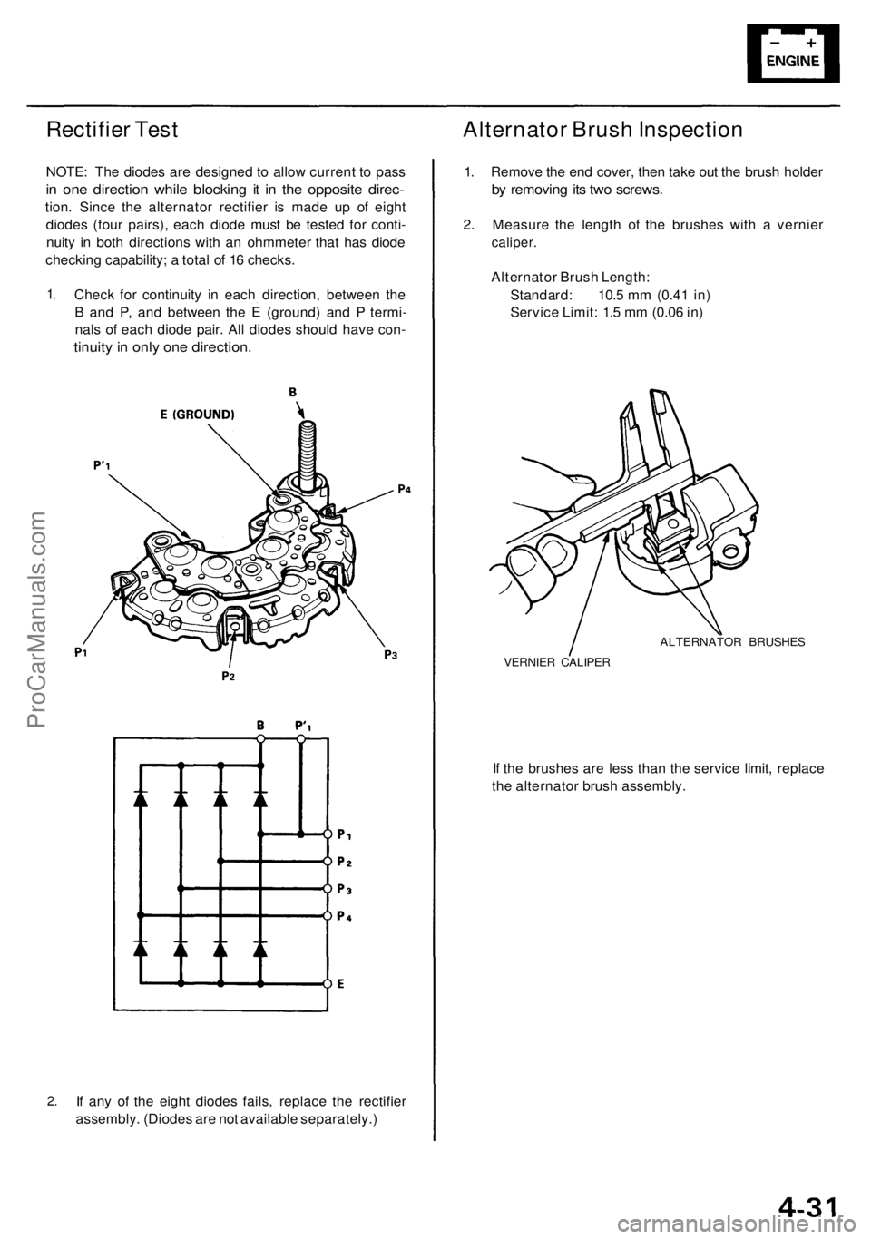
NOTE: The diodes are designed to allow current to pass
in one direction while blocking it in the opposite direc-
tion. Since the alternator rectifier is made up of eight
diodes (four pairs), each diode must be tested for conti-
nuity in both directions with an ohmmeter that has diode
checking capability; a total of 16 checks.
1.
Check for continuity in each direction, between the
B and P, and between the E (ground) and P termi-
nals of each diode pair. All diodes should have con-
tinuity in only one direction.
2.
If any of the eight diodes fails, replace the rectifier
assembly. (Diodes are not available separately.)
Alternator Brush Inspection
1. Remove the end cover, then take out the brush holder
by removing its two screws.
2. Measure the length of the brushes with a vernier
caliper.
Alternator Brush Length:
Standard: 10.5 mm (0.41 in)
Service Limit: 1.5 mm (0.06 in)
ALTERNATOR BRUSHES
VERNIER CALIPER
If the brushes are less than the service limit, replace
the alternator brush assembly.ProCarManuals.com
Page 351 of 1954
Charging System
Rotor Slip Ring Test
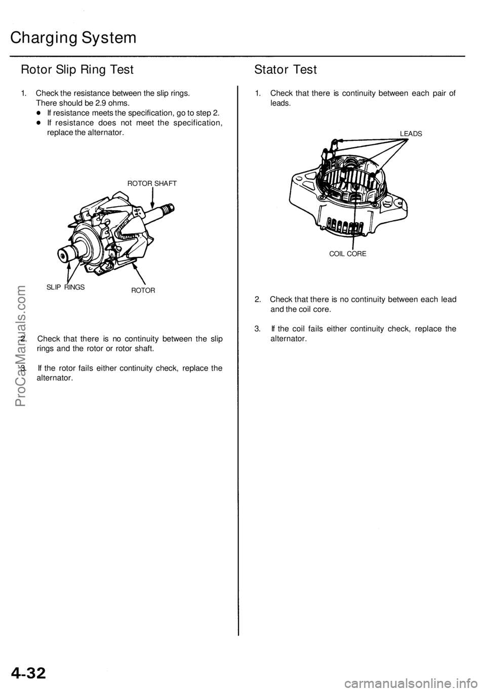
1. Check the resistance between the slip rings.
There should be 2.9 ohms.
If resistance meets the specification, go to step 2.
If resistance does not meet the specification,
replace the alternator.
ROTOR SHAFT
SLIP RINGS
ROTOR
2. Check that there is no continuity between the slip
rings and the rotor or rotor shaft.
3. If the rotor fails either continuity check, replace the
alternator.
Stator Test
1. Check that there is continuity between each pair of
leads.
LEADS
COIL CORE
2. Check that there is no continuity between each lead
and the coil core.
3. If the coil fails either continuity check, replace the
alternator.ProCarManuals.com
Page 352 of 1954
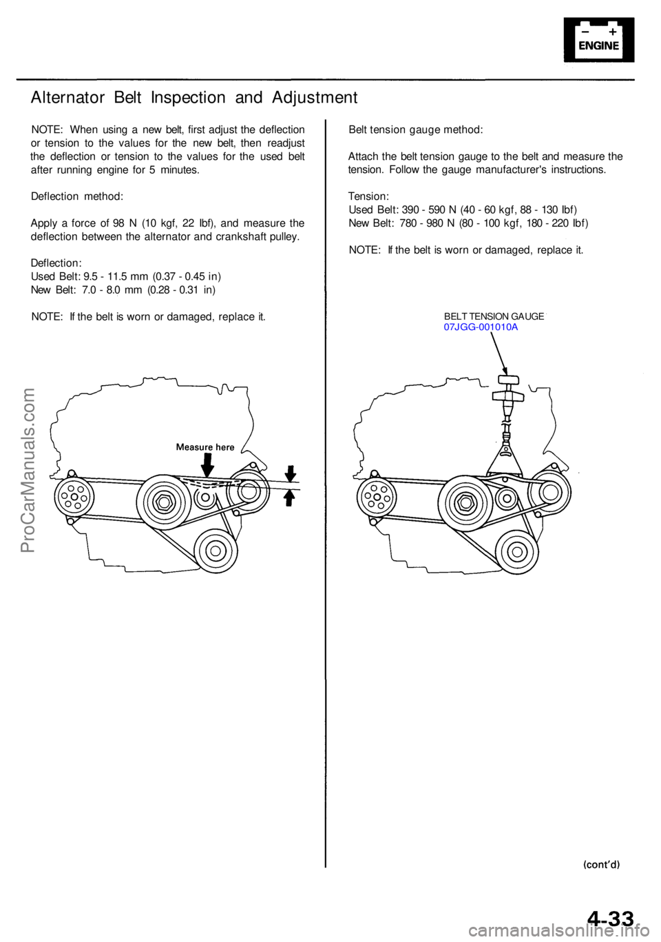
Alternator Bel t Inspectio n an d Adjustmen t
NOTE: Whe n usin g a ne w belt , firs t adjus t th e deflectio n
o r tensio n t o th e value s fo r th e ne w belt , the n readjus t
th e deflectio n o r tensio n t o th e value s fo r th e use d bel t
afte r runnin g engin e fo r 5 minutes .
Deflectio n method :
Appl y a forc e o f 9 8 N (1 0 kgf , 2 2 Ibf) , an d measur e th e
deflectio n betwee n th e alternato r an d crankshaf t pulley .
Deflection :
Use d Belt : 9. 5 - 11. 5 m m (0.3 7 - 0.4 5 in )
Ne w Belt : 7. 0 - 8. 0 m m (0.2 8 - 0.3 1 in )
NOTE : I f th e bel t i s wor n o r damaged , replac e it . Bel
t tensio n gaug e method :
Attac h th e bel t tensio n gaug e t o th e bel t an d measur e th e
tension . Follo w th e gaug e manufacturer' s instructions .
Tension :
Use d Belt : 39 0 - 59 0 N (4 0 - 6 0 kgf , 8 8 - 13 0 Ibf )
Ne w Belt : 78 0 - 98 0 N (8 0 - 10 0 kgf , 18 0 - 22 0 Ibf )
NOTE : I f th e bel t i s wor n o r damaged , replac e it .
BEL T TENSIO N GAUG E07JGG-001010 A
ProCarManuals.com
Page 369 of 1954
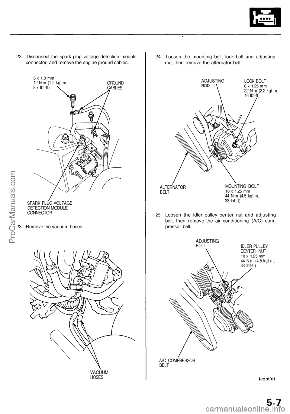
22. Disconnect the spark plug voltage detection module
connector, and remove the engine ground cables.
6 x 1.0 mm
12 N-m (1.2 kgf-m,
8.7 Ibf-ft)
GROUND
CABLES
SPARK PLUG VOLTAGE
DETECTION MODULE
CONNECTOR
23. Remove the vacuum hoses.
VACUUM
HOSES
24. Loosen the mounting bolt, lock bolt and adjusting
rod, then remove the alternator belt.
ADJUSTING
ROD
LOCK BOLT
8 x
1.25
mm
22 N-m (2.2 kgf-m,
16 Ibf-ft)
ALTERNATOR
BELT
MOUNTING BOLT
10 x
1.25
mm
44 N-m (4.5 kgf-m,
33 Ibf-ft)
25.
Loosen the idler pulley center nut and adjusting
bolt, then remove the air conditioning (A/C) com-
pressor belt.
ADJUSTING
BOLT
IDLER PULLEY
CENTER NUT
10 x
1.25
mm
44 N-m (4.5 kgf-m,
33 Ibf-ft)
A/C COMPRESSOR
BELTProCarManuals.com