Timing ACURA RL KA9 1996 Service User Guide
[x] Cancel search | Manufacturer: ACURA, Model Year: 1996, Model line: RL KA9, Model: ACURA RL KA9 1996Pages: 1954, PDF Size: 61.44 MB
Page 545 of 1954
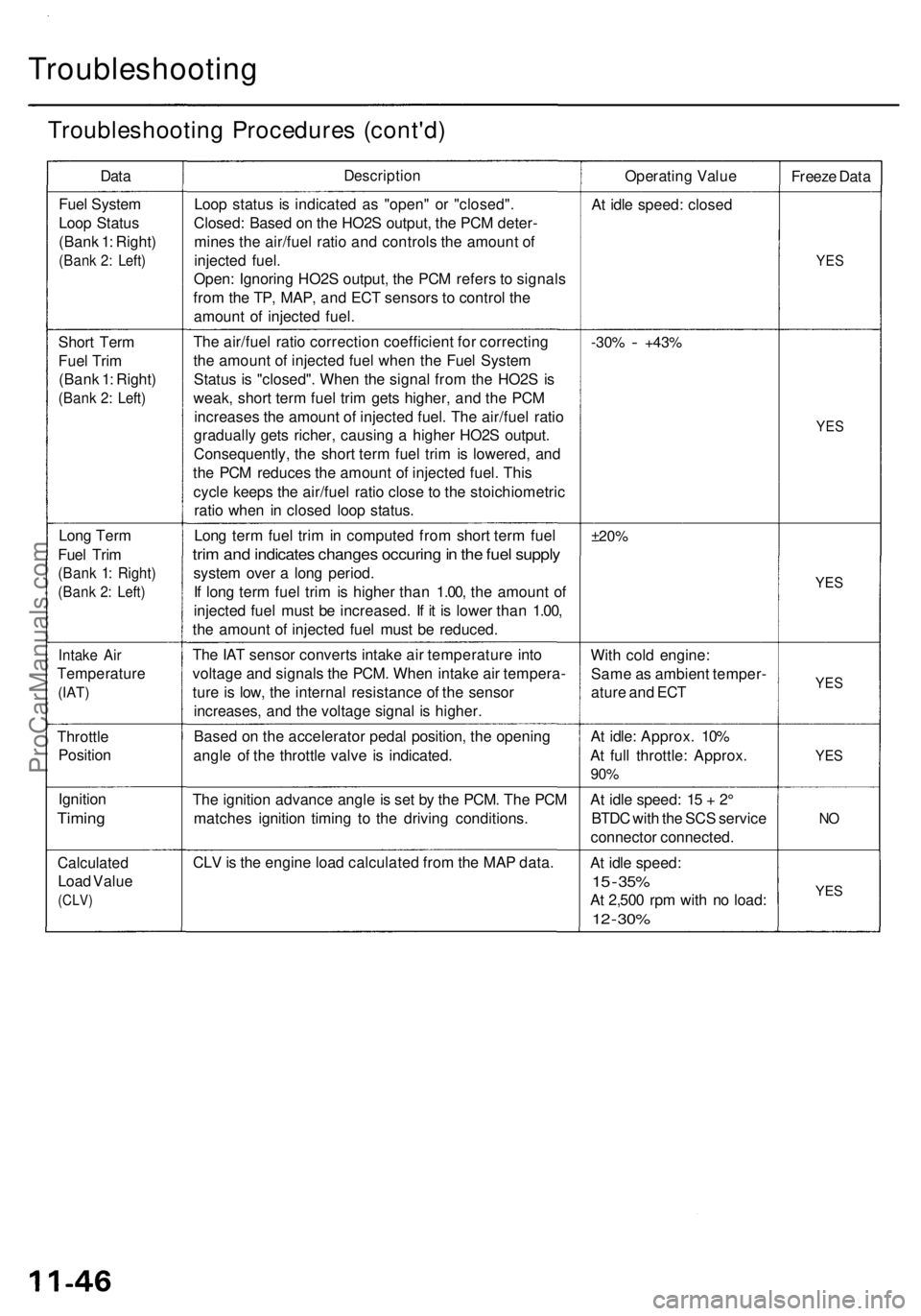
Troubleshooting
Troubleshooting Procedures (cont'd)
Data
Description
Operating Value
Freeze Data
Fuel System
Loop Status
(Bank 1: Right)
(Bank 2: Left)
Loop status is indicated as "open" or "closed".
Closed: Based on the HO2S output, the PCM deter-
mines the air/fuel ratio and controls the amount of
injected fuel.
Open: Ignoring HO2S output, the PCM refers to signals
from the TP, MAP, and ECT sensors to control the
amount of injected fuel.
At idle speed: closed
YES
Short Term
Fuel Trim
(Bank 1: Right)
(Bank 2: Left)
The air/fuel ratio correction coefficient for correcting
the amount of injected fuel when the Fuel System
Status is "closed". When the signal from the HO2S is
weak, short term fuel trim gets higher, and the PCM
increases the amount of injected fuel. The air/fuel ratio
gradually gets richer, causing a higher HO2S output.
Consequently, the short term fuel trim is lowered, and
the PCM reduces the amount of injected fuel. This
cycle keeps the air/fuel ratio close to the stoichiometric
ratio when in closed loop status.
-30%
-
+43%
YES
Long Term
Fuel Trim
(Bank 1: Right)
(Bank 2: Left)
Long term fuel trim in computed from short term fuel
trim and indicates changes occuring in the fuel supply
system over a long period.
If long term fuel trim is higher than 1.00, the amount of
injected fuel must be increased. If it is lower than 1.00,
the amount of injected fuel must be reduced.
±20%
YES
Intake Air
Temperature
(IAT)
The IAT sensor converts intake air temperature into
voltage and signals the PCM. When intake air tempera-
ture is low, the internal resistance of the sensor
increases, and the voltage signal is higher.
With cold engine:
Same as ambient temper-
ature and ECT
YES
Throttle
Position
Based on the accelerator pedal position, the opening
angle of the throttle valve is indicated.
At idle: Approx. 10%
At full throttle: Approx.
90%
YES
Ignition
Timing
The ignition advance angle is set by the PCM. The PCM
matches ignition timing to the driving conditions.
At idle speed: 15 + 2°
BTDC with the SCS service
connector connected.
NO
Calculated
Load Value
(CLV)
CLV is the engine load calculated from the MAP data.
At idle speed:
15
-
35%
At 2,500 rpm with no load:
12
-
30%
YESProCarManuals.com
Page 712 of 1954
Description
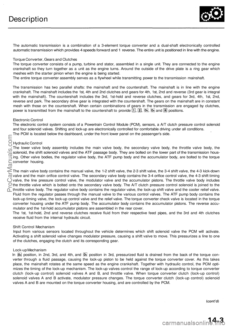
The automatic transmission is a combination of a 3-element torque converter and a dual-shaft electronically controlled
automatic transmission which provides 4 speeds forward and 1 reverse. The entire unit is positioned in line with the engine.
Torque Converter, Gears and Clutches
The torque converter consists of a pump, turbine and stator, assembled in a single unit. They are connected to the engine
crankshaft so they turn together as a unit as the engine turns. Around the outside of the drive plate is a ring gear which
meshes with the starter pinion when the engine is being started.
The entire torque converter assembly serves as a flywheel while transmitting power to the transmission mainshaft.
The transmission has two parallel shafts: the mainshaft and the countershaft. The mainshaft is in line with the engine
crankshaft. The mainshaft includes the 1st, 4th and 2nd clutches and gears for 4th, 1st, 2nd and reverse (3rd gear is integral
with the mainshaft). The countershaft includes the 3rd, 1st-hold and reverse clutches, and gears for 3rd, 4th, 1st, 2nd,
reverse and park. The secondary drive gear is integrated with the countershaft. The gears on the mainshaft are in constant
mesh with those on the countershaft. When certain combinations of gears in the transmission are engaged by clutches,
power is transmitted from the mainshaft to the countershaft to provide , , , and positions.
Electronic Control
The electronic control system consists of a Powertrain Control Module (PCM), sensors, a A/T clutch pressure control solenoid
and four solenoid valves. Shifting and lock-up are electronically controlled for comfortable driving under all conditions.
The PCM is located below the dashboard, under the front lower panel on the passenger's side.
Hydraulic Control
The lower valve body assembly includes the main valve body, the secondary valve body, the throttle valve body, the
solenoid, the shift solenoid valves and the ATF passage body. They are bolted on the lower part of the transmission hous-
ing. Other valve bodies, the regulator valve body, the ATF pump body and the accumulator body, are bolted to the torque
converter housing.
The main valve body contains the manual valve, the 1-2 shift valve, the 2-3 shift valve, the 3-4 shift valve, the 4-3 kick-down
valve and the main orifice control valve. The secondary valve body contains the 3-4 orifice control valve, the 4-3 shift timing
valve, the line pressure control valve, the modulator valve and the accumulator pistons. The throttle valve body includes
the throttle valve which is bolted onto the secondary valve body. The A/T clutch pressure control solenoid is joined to the
throttle valve body. The regulator valve body contains the regulator valve, the lock-up shift valve and the cooler relief valve.
Fluid from the regulator passes through the manual valve to the various control valves. The ATF pump body contains the
lock-up timing valve, the lock-up control valve and the relief valve. The torque converter check valve is located in the torque
converter housing under the ATF pump body. The accumulator body contains the accumulator pistons. The reverse accu-
mulator and the 1st-hold accumulator pistons are assembled in the rear cover.
The 1st, 1st-hold, 2nd and reverse clutches receive fluid from their respective feed pipes, and the 3rd and 4th clutches
receive fluid from the internal hydraulic circuit.
Shift Control Mechanism
Input from various sensors located throughout the vehicle determines which shift solenoid valve the PCM will activate.
Activating a shift solenoid valve changes modulator pressure, causing a shift valve to move. This pressurizes a line to one
of the clutches, engaging the clutch and its corresponding gear.
Lock-up Mechanism
In position, in 2nd, 3rd, and 4th, and position in 3rd, pressurized fluid is drained from the back of the torque con-
verter through a fluid passage, causing the lock-up piston to be held against the torque converter cover. As this takes
place, the mainshaft rotates at the same speed as the engine crankshaft. Together with hydraulic control, the PCM opti-
mizes the timing of the lock-up mechanism. The lock-up valves control the range of lock-up according to torque converter
clutch (lock-up control) solenoid valves A and B, and throttle valve. When torque converter clutch (lock-up control)
solenoid valves A and B activate, modulator pressure changes. The torque converter clutch (lock-up control) solenoid
valves A and B are mounted on the torque converter housing, and are controlled by the PCM.ProCarManuals.com
Page 734 of 1954
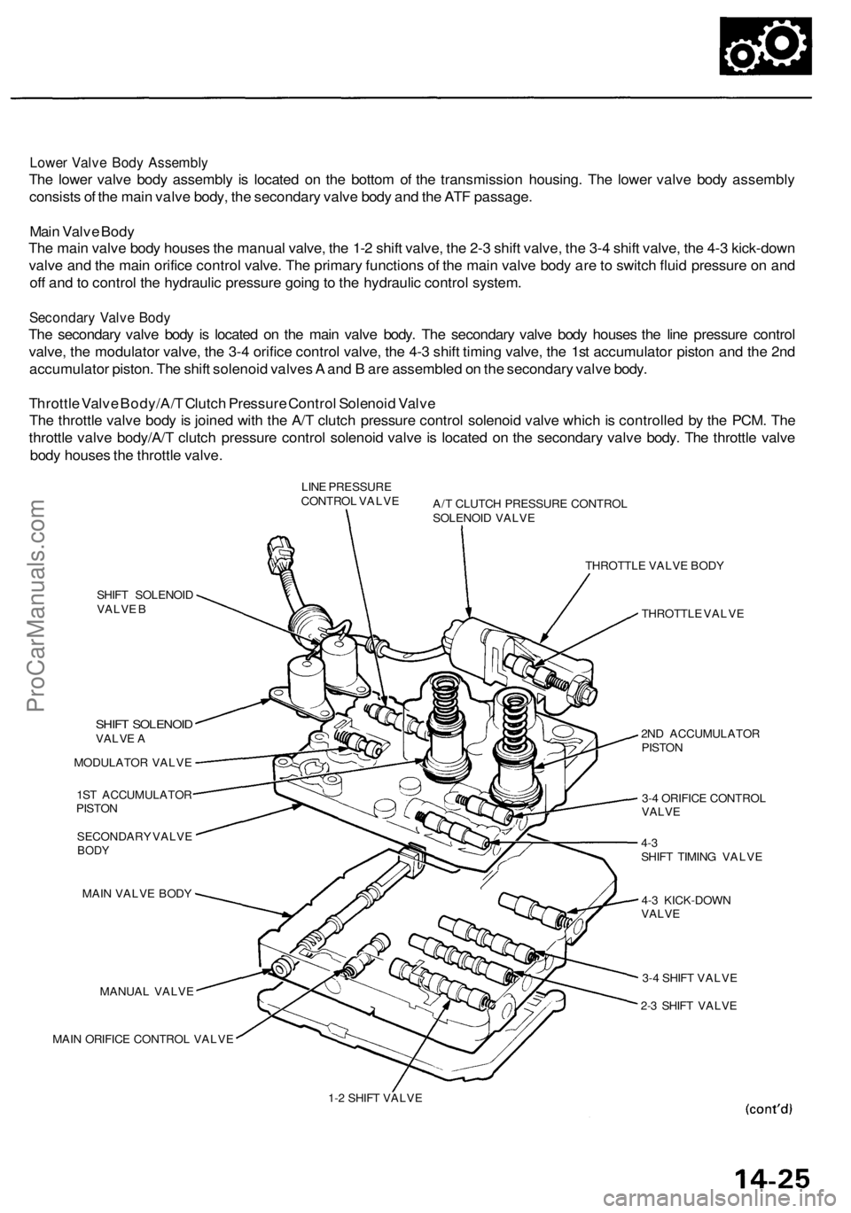
Lower Valve Body Assembly
The lower valve body assembly is located on the bottom of the transmission housing. The lower valve body assembly
consists of the main valve body, the secondary valve body and the ATF passage.
Main Valve Body
The main valve body houses the manual valve, the 1-2 shift valve, the 2-3 shift valve, the 3-4 shift valve, the 4-3 kick-down
valve and the main orifice control valve. The primary functions of the main valve body are to switch fluid pressure on and
off and to control the hydraulic pressure going to the hydraulic control system.
Secondary Valve Body
The secondary valve body is located on the main valve body. The secondary valve body houses the line pressure control
valve, the modulator valve, the 3-4 orifice control valve, the 4-3 shift timing valve, the 1st accumulator piston and the 2nd
accumulator piston. The shift solenoid valves A and B are assembled on the secondary valve body.
Throttle Valve Body/A/T Clutch Pressure Control Solenoid Valve
The throttle valve body is joined with the A/T clutch pressure control solenoid valve which is controlled by the PCM. The
throttle valve body/A/T clutch pressure control solenoid valve is located on the secondary valve body. The throttle valve
body houses the throttle valve.
LINE PRESSURE
CONTROL VALVE
A/T CLUTCH PRESSURE CONTROL
SOLENOID VALVE
SHIFT SOLENOID
VALVE B
SHIFT SOLENOID
VALVE A
MODULATOR VALVE
1ST ACCUMULATOR
PISTON
SECONDARY VALVE
BODY
MAIN VALVE BODY
MANUAL VALVE
MAIN ORIFICE CONTROL VALVE
THROTTLE VALVE BODY
THROTTLE VALVE
2ND ACCUMULATOR
PISTON
3-4 ORIFICE CONTROL
VALVE
4-3
SHIFT TIMING VALVE
4-3 KICK-DOWN
VALVE
3-4 SHIFT VALVE
2-3 SHIFT VALVE
1-2 SHIFT VALVEProCarManuals.com
Page 735 of 1954
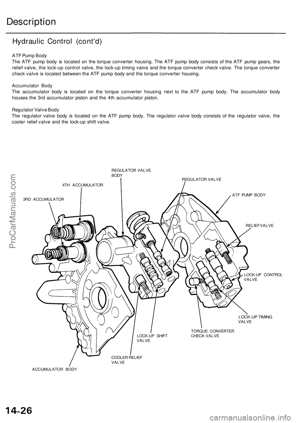
Hydraulic Control (cont'd)
ATF Pump Body
The ATF pump body is located on the torque converter housing. The ATF pump body consists of the ATF pump gears, the
relief valve, the lock-up control valve, the lock-up timing valve and the torque converter check valve. The torque converter
check valve is located between the ATF pump body and the torque converter housing.
Accumulator Body
The accumulator body is located on the torque converter housing next to the ATF pump body. The accumulator body
houses the 3rd accumulator piston and the 4th accumulator piston.
Regulator Valve Body
The regulator valve body is located on the ATF pump body. The regulator valve body consists of the regulator valve, the
cooler relief valve and the lock-up shift valve.
REGULATOR VALVE
BODY
REGULATOR VALVE
4TH ACCUMULATOR
3RD ACCUMULATOR
ATF PUMP BODY
RELIEF VALVE
LOCK-UP CONTROL
VALVE
LOCK-UP TIMING
VALVE
TORQUE CONVERTER
CHECK VALVE
COOLER RELIEF
VALVE
ACCUMULATOR BODY
LOCK-UP SHIFT
VALVE
DescriptionProCarManuals.com
Page 748 of 1954
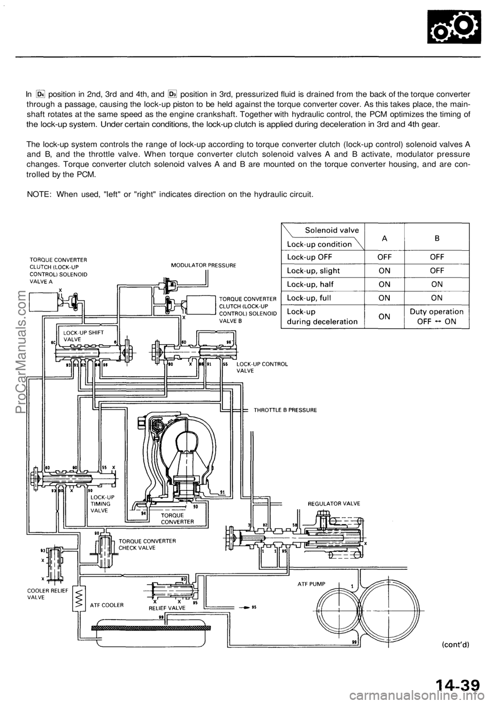
In position in 2nd, 3rd and 4th, and position in 3rd, pressurized fluid is drained from the back of the torque converter
through a passage, causing the lock-up piston to be held against the torque converter cover. As this takes place, the main-
shaft rotates at the same speed as the engine crankshaft. Together with hydraulic control, the PCM optimizes the timing of
the lock-up system. Under certain conditions, the lock-up clutch is applied during deceleration in 3rd and 4th gear.
The lock-up system controls the range of lock-up according to torque converter clutch (lock-up control) solenoid valves A
and B, and the throttle valve. When torque converter clutch solenoid valves A and B activate, modulator pressure
changes. Torque converter clutch solenoid valves A and B are mounted on the torque converter housing, and are con-
trolled by the PCM.
NOTE: When used, "left" or "right" indicates direction on the hydraulic circuit.ProCarManuals.com
Page 750 of 1954
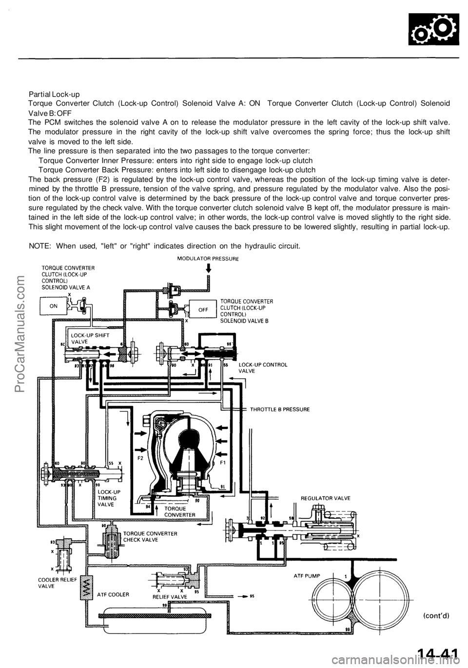
Partial Lock-up
Torque Converter Clutch (Lock-up Control) Solenoid Valve A: ON Torque Converter Clutch (Lock-up Control) Solenoid
Valve B: OFF
The PCM switches the solenoid valve A on to release the modulator pressure in the left cavity of the lock-up shift valve.
The modulator pressure in the right cavity of the lock-up shift valve overcomes the spring force; thus the lock-up shift
valve is moved to the left side.
The line pressure is then separated into the two passages to the torque converter:
Torque Converter Inner Pressure: enters into right side to engage lock-up clutch
Torque Converter Back Pressure: enters into left side to disengage lock-up clutch
The back pressure (F2) is regulated by the lock-up control valve, whereas the position of the lock-up timing valve is deter-
mined by the throttle B pressure, tension of the valve spring, and pressure regulated by the modulator valve. Also the posi-
tion of the lock-up control valve is determined by the back pressure of the lock-up control valve and torque converter pres-
sure regulated by the check valve. With the torque converter clutch solenoid valve B kept off, the modulator pressure is main-
tained in the left side of the lock-up control valve; in other words, the lock-up control valve is moved slightly to the right side.
This slight movement of the lock-up control valve causes the back pressure to be lowered slightly, resulting in partial lock-up.
NOTE: When used, "left" or "right" indicates direction on the hydraulic circuit.ProCarManuals.com
Page 751 of 1954
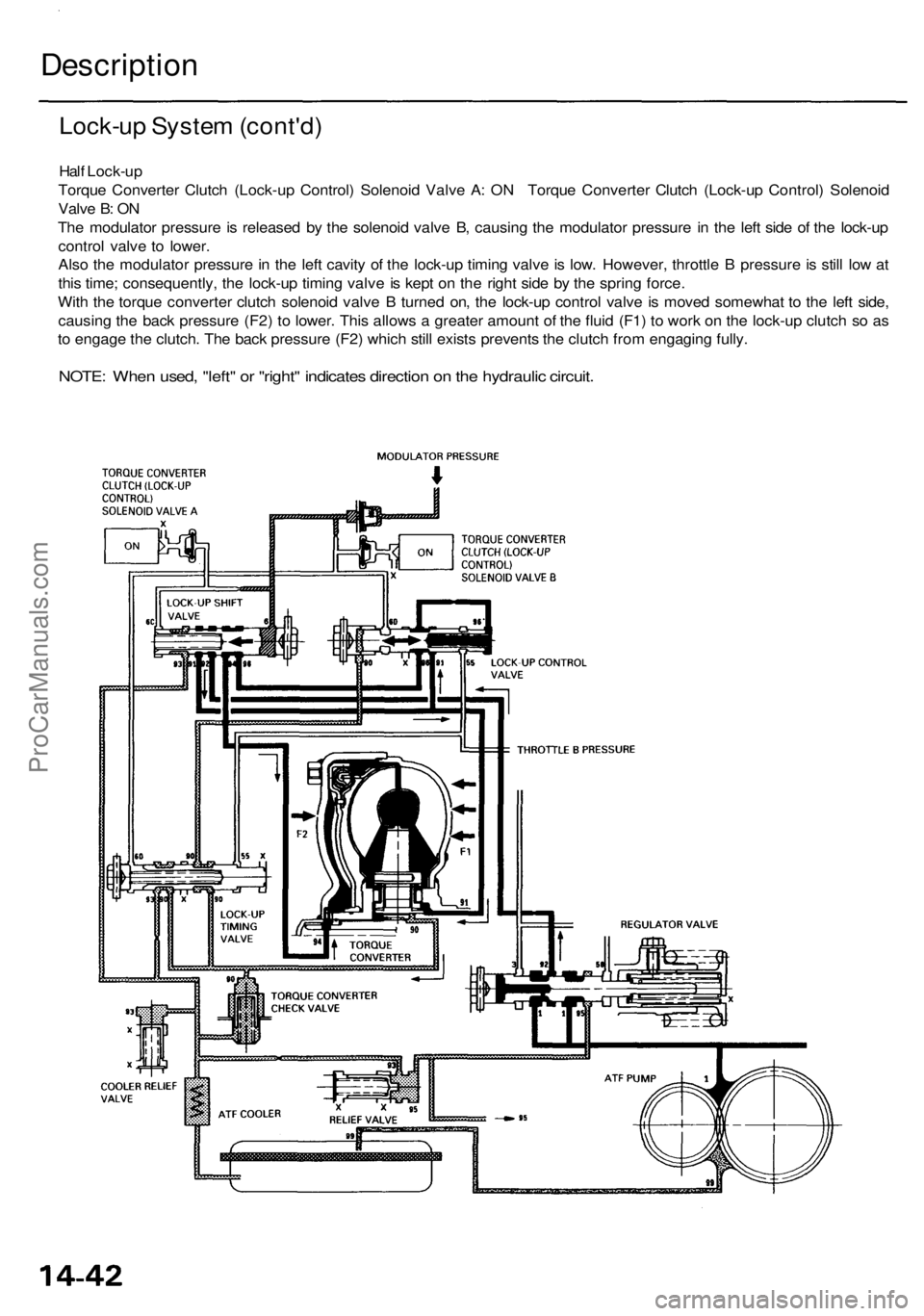
Lock-up System (cont'd)
Half Lock-up
Torque Converter Clutch (Lock-up Control) Solenoid Valve A: ON Torque Converter Clutch (Lock-up Control) Solenoid
Valve B: ON
The modulator pressure is released by the solenoid valve B, causing the modulator pressure in the left side of the lock-up
control valve to lower.
Also the modulator pressure in the left cavity of the lock-up timing valve is low. However, throttle B pressure is still low at
this time; consequently, the lock-up timing valve is kept on the right side by the spring force.
With the torque converter clutch solenoid valve B turned on, the lock-up control valve is moved somewhat to the left side,
causing the back pressure (F2) to lower. This allows a greater amount of the fluid (F1) to work on the lock-up clutch so as
to engage the clutch. The back pressure (F2) which still exists prevents the clutch from engaging fully.
NOTE: When used, "left" or "right" indicates direction on the hydraulic circuit.
DescriptionProCarManuals.com
Page 752 of 1954
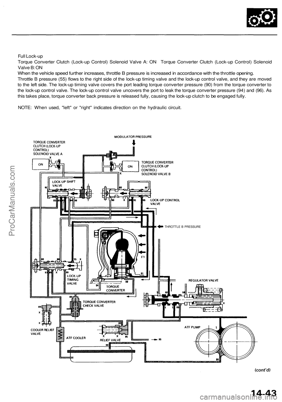
Full Lock-up
Torque Converter Clutch (Lock-up Control) Solenoid Valve A: ON Torque Converter Clutch (Lock-up Control) Solenoid
Valve B: ON
When the vehicle speed further increases, throttle B pressure is increased in accordance with the throttle opening.
Throttle B pressure (55) flows to the right side of the lock-up timing valve and the lock-up control valve, and they are moved
to the left side. The lock-up timing valve covers the port leading torque converter pressure (90) from the torque converter to
the lock-up control valve. The lock-up control valve uncovers the port to leak the torque converter pressure (94) and (96). As
this takes place, torque converter back pressure is released fully, causing the lock-up clutch to be engaged fully.
NOTE: When used, "left" or "right" indicates direction on the hydraulic circuit.
THROTTLE B PRESSUREProCarManuals.com
Page 1154 of 1954
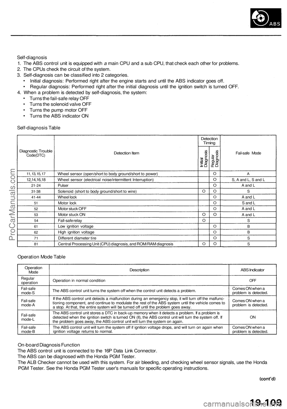
Self-diagnosis
1. The ABS control unit is equipped with a main CPU and a sub CPU, that check each other for problems.
2. The CPUs check the circuit of the system.
3. Self-diagnosis can be classified into 2 categories.
Initial diagnosis: Performed right after the engine starts and until the ABS indicator goes off.
Regular diagnosis: Performed right after the initial diagnosis until the ignition switch is turned OFF.
4. When a problem is detected by self-diagnosis, the system:
Turns the fail-safe relay OFF
Turns the solenoid valve OFF
Turns the pump motor OFF
Turns the ABS indicator ON
Self-diagnosis Table
Diagnostic Trouble
Code(DTC)
11, 13, 15, 17
12,14,16,18
21-24
31-38
41-44
51
52
53
54
61
62
71
81
Detection Item
Wheel sensor (open/short to body ground/short to power)
Wheel sensor (electrical noise/intermittent Interruption)
Pulser
Solenoid (short to body ground/short to wire)
Wheel lock
Motor lock
Motor stuck OFF
Motor stuck ON
Fall-safe relay
Low ignition voltage
High ignition voltage
Different diameter tire
Central Processing Unit (CPU) diagnosis, and ROM/RAM diagnosis
Detection
Timing
Initial
Diagnosis
O
O
O
O
Regular
Diagnosis
O
O
O
O
O
O
O
O
O
O
O
O
Fail-safe Mode
A
S, A and L, S and L
A and L
S
A and L
S and L
A and L
A and L
S
B
B
S
S
Operation Mode Table
Operation
Mode
Regular
operation
Fail-safe
mode-S
Fail-safe
mode-A
Fail-safe
mode-L
Fail-safe
mode-B
Description
Operation in normal condition
The ABS control unit turns the system off when the control unit detects a problem.
If the ABS control unit detects a malfunction during an emergency stop, it will turn off the malfunc-
tioning component, and continue to modulate the rest of the ABS system until the vehicle comes to
a stop. At that, the entire system will be turned off until the problem goes away.
The ABS control unit stores a DTC in back-up memory when it detects a problem. If a problem is
detected when the ignition switch is turned ON (II), the ABS control unit will turn the system off. If
the problem goes away, the ABS control unit will turn the system on again.
The ABS control unit will turn the system off if ignition voltage drops, and will turn on again when
ignition voltage returns to normal.
ABS
Indicator
OFF
Comes ON when a
problem is detected.
Comes ON when a
problem is detected.
ON
Comes ON when a
problem is detected.
On-board Diagnosis Function
The ABS control unit is connected to the 16P Data Link Connector.
The ABS can be diagnosed with the Honda PGM Tester.
The ALB Checker cannot be used with this system. For air bleeding, and checking wheel sensor signals, use the Honda
PGM Tester. See the Honda PGM Tester user's manuals for specific operating instructions.
ProCarManuals.com
Page 1164 of 1954
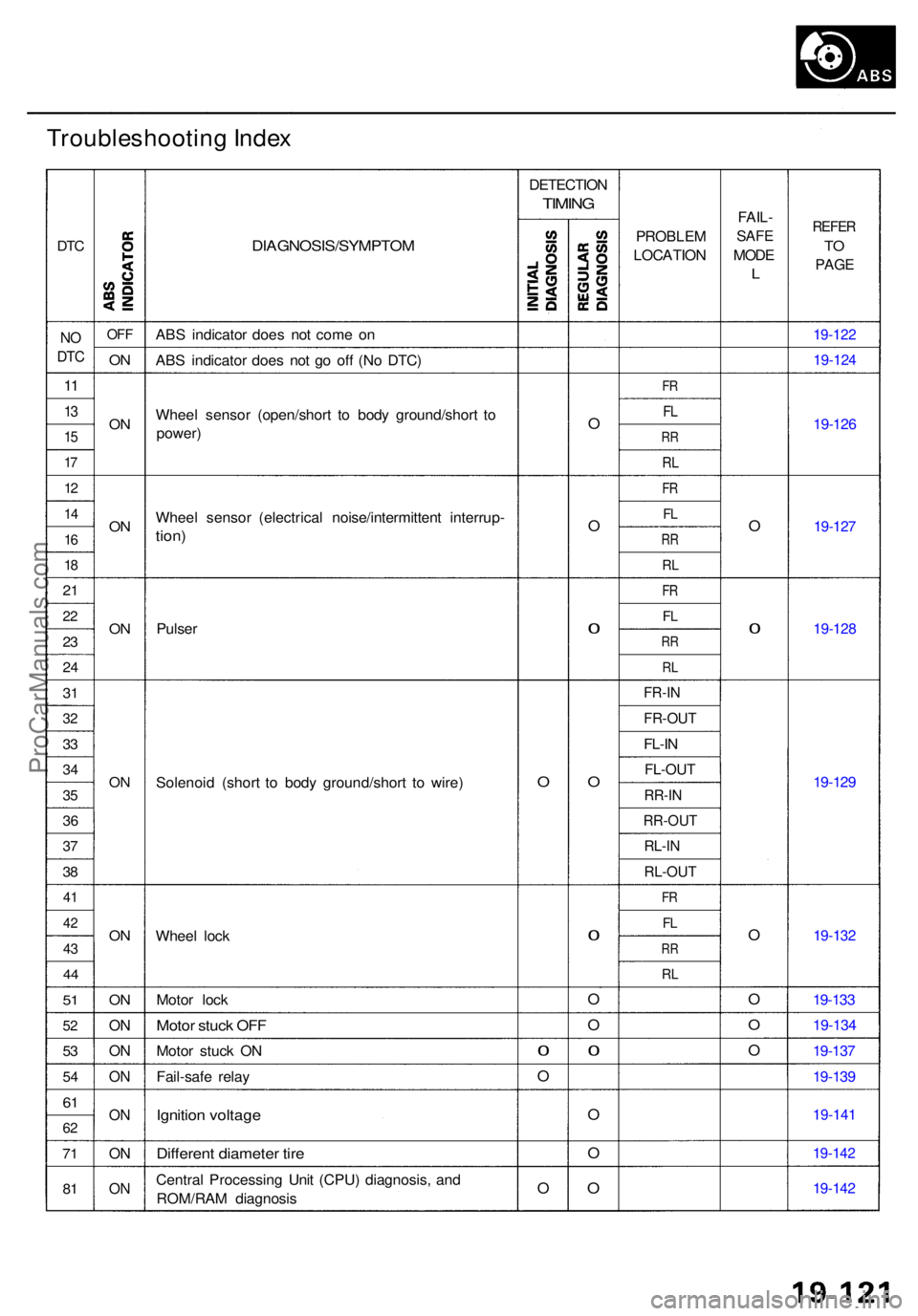
Troubleshooting Inde x
DTC
NO
DT C
11
13
1 5
17
1 2
1 4
16
18
2 1
2 2
23
2 4
31
3 2
33
3 4
35
3 6
37
3 8
4 1
4 2
43
4 4
51
5 2
53
5 4
61
6 2
71
81
OF F
ON
O N
ON
O N
O N
ON
O N
ON
O N
O N
O N
ON
O N
DIAGNOSIS/SYMPTO M
ABS indicato r doe s no t com e o n
AB S indicato r doe s no t g o of f (N o DTC )
Whee l senso r (open/shor t t o bod y ground/shor t t o
power )
Whee l senso r (electrica l noise/intermitten t interrup -
tion)
Pulse r
Solenoi d (shor t t o bod y ground/shor t t o wire )
Whee l loc k
Moto r loc k
Moto r stuc k OF F
Moto r stuc k O N
Fail-saf e rela y
Ignitio n voltag e
Differen t diamete r tir e
Centra l Processin g Uni t (CPU ) diagnosis , an d
ROM/RA M diagnosi s DETECTIO
N
TIMING
O
0
O
O
O
O
0
O
0
O
O
0
O
O
O
PROBLE M
LOCATIO N
FR
FL
R R
RL
FR
FL
R R
RL
FR
FL
R R
R L
FR-I N
FR-OU T
FL-IN
FL-OU T
RR-IN
RR-OU T
RL-IN
RL-OU T
FR
FL
R R
RL
FAIL -
SAFE
MOD E
L
O
0
O
O
O
O
REFE R
TO
PAG E
19-12 2
19-124
19-126
19-127
19-12 8
19-129
19-13 2
19-133
19-13 4
19-13 7
19-13 9
19-14 1
19-142
19-142
ProCarManuals.com