coolant ACURA RL KA9 1996 Service User Guide
[x] Cancel search | Manufacturer: ACURA, Model Year: 1996, Model line: RL KA9, Model: ACURA RL KA9 1996Pages: 1954, PDF Size: 61.44 MB
Page 493 of 1954
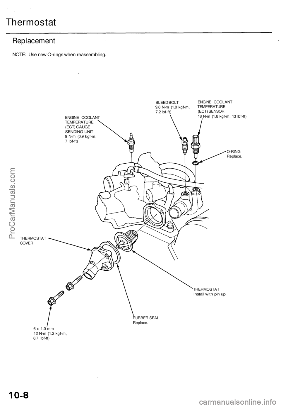
Thermostat
Replacement
NOTE: Use new O-rings when reassembling.
BLEED BOLT
9.8 N-m (1.0 kgf-m,
7.2 Ibf-ft)
ENGINE COOLANT
TEMPERATURE
(ECT) GAUGE
SENDING UNIT
9 N-m (0.9 kgf-m,
7 Ibf-ft)
ENGINE COOLANT
TEMPERATURE
(ECT) SENSOR
18 N-m (1.8 kgf-m, 13 Ibf-ft)
THERMOSTAT
COVER
O-RING
Replace.
THERMOSTAT
Install with pin up.
RUBBER SEAL
Replace.
6 x 1.0 mm
12 N-m (1.2 kgf-m,
8.7 Ibf-ft)ProCarManuals.com
Page 496 of 1954
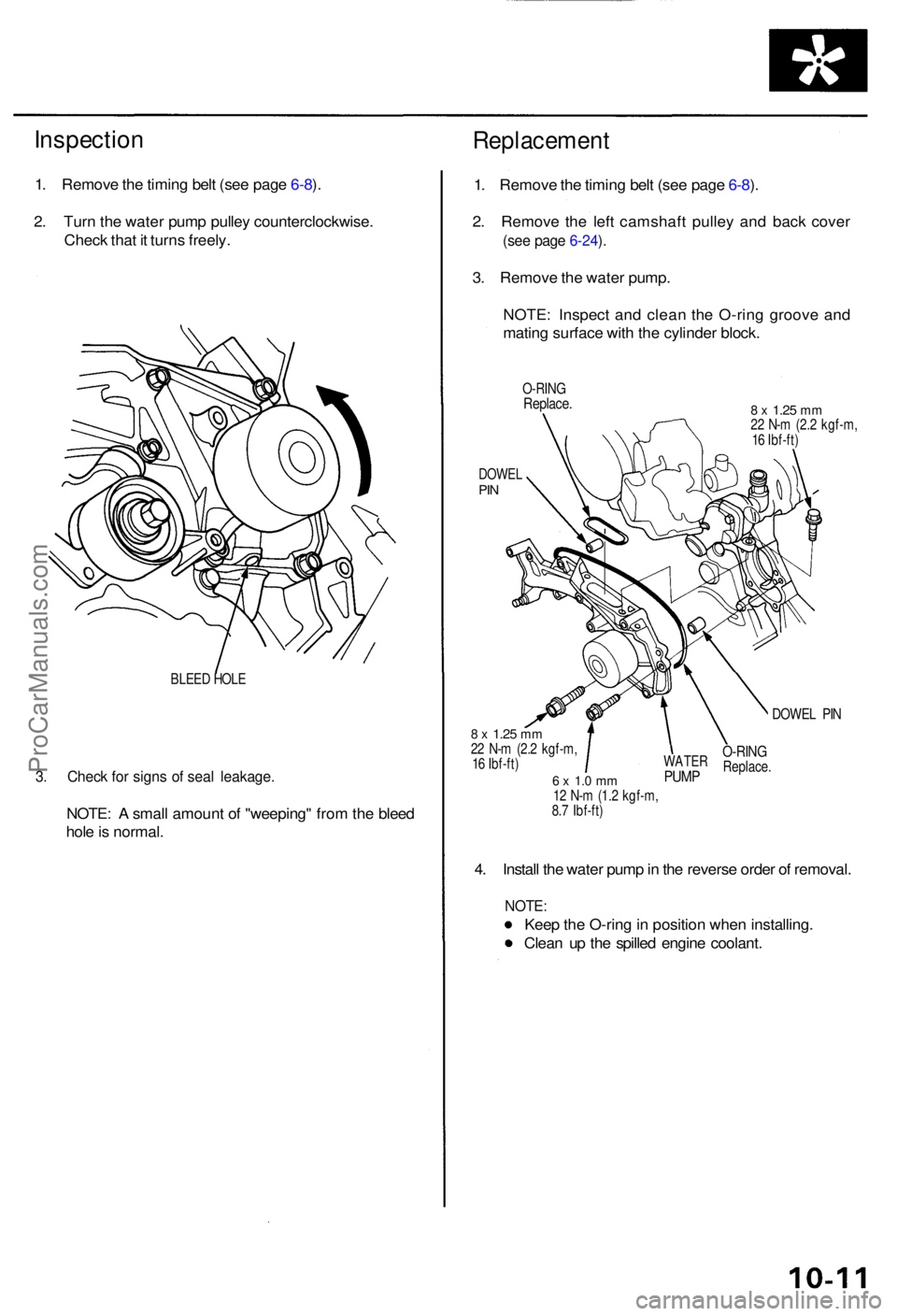
Inspection
1. Remov e th e timin g bel t (se e pag e 6-8 ).
2 . Tur n th e wate r pum p pulle y counterclockwise .
Chec k tha t i t turn s freely .
BLEED HOL E
3. Chec k fo r sign s o f sea l leakage .
NOTE: A smal l amoun t o f "weeping " fro m th e blee d
hol e is normal .
Replacemen t
1. Remov e th e timin g bel t (se e pag e 6-8 ).
2 . Remov e th e lef t camshaf t pulle y an d bac k cove r
(see pag e 6-24 ).
3 . Remov e th e wate r pump .
NOTE : Inspec t an d clea n th e O-rin g groov e an d
matin g surfac e wit h th e cylinde r block .
O-RIN GReplace .8 x 1.2 5 mm22 N- m (2. 2 kgf-m ,
1 6 Ibf-ft )
DOWE LPIN
DOWE L PI N
8 x 1.2 5 mm22 N- m (2. 2 kgf-m ,
1 6 Ibf-ft )
6 x 1. 0 m m12 N- m (1. 2 kgf-m ,
8. 7 Ibf-ft )
4. Instal l th e wate r pum p in th e revers e orde r o f removal .
NOTE:
Keep th e O-rin g in positio n whe n installing .
Clea n u p th e spille d engin e coolant .
WATERPUMP
O-RIN GReplace .
ProCarManuals.com
Page 544 of 1954
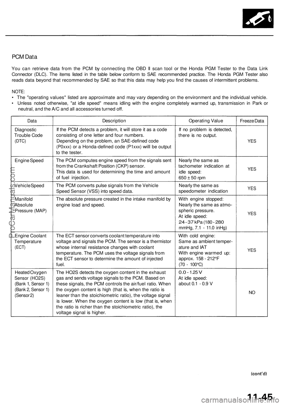
PCM Data
You can retrieve data from the PCM by connecting the OBD II scan tool or the Honda PGM Tester to the Data Link
Connector (DLC). The items listed in the table below conform to SAE recommended practice. The Honda PGM Tester also
reads data beyond that recommended by SAE so that this data may help you find the causes of intermittent problems.
NOTE:
• The "operating values" listed are approximate and may vary depending on the environment and the individual vehicle.
• Unless noted otherwise, "at idle speed" means idling with the engine completely warmed up, transmission in Park or
neutral, and the A/C and all accessories turned off.
Data
Description
Operating Value
Freeze Data
Diagnostic
Trouble Code
(DTC)
If the PCM detects a problem, it will store it as a code
consisting of one letter and four numbers.
Depending on the problem, an SAE-defined code
(P0xxx)
or a
Honda-defined code
(P1xxx)
will
be
output
to the tester.
If no problem is detected,
there is no output.
YES
Engine Speed
The PCM computes engine speed from the signals sent
from the Crankshaft Position (CKP) sensor.
This data is used for determining the time and amount
of fuel injection.
Nearly the same as
tachometer indication at
idle speed:
650 ± 50 rpm
YES
Vehicle Speed
The PCM converts pulse signals from the Vehicle
Speed Sensor (VSS) into speed data.
Nearly the same as
speedometer indication
YES
Manifold
Absolute
Pressure (MAP)
The absolute pressure created in the intake manifold by
engine load and speed.
With engine stopped:
Nearly the same as atmo-
spheric pressure.
At idle speed:
24 - 37
kPa
(180
-
280
mmHg, 7.1 - 11.0 inHg)
YES
Engine Coolant
Temperature
(ECT)
The ECT sensor converts coolant temperature into
voltage and signals the PCM. The sensor is a thermistor
whose internal resistance changes with coolant
temperature. The PCM uses the voltage signals from
the ECT sensor to determine the amount of injected
fuel.
With cold engine:
Same as ambient temper-
ature and IAT
With engine warmed up:
approx. 158 - 212°F
(70 - 100°C)
YES
Heated Oxygen
Sensor (HO2S)
(Bank 1, Sensor 1)
(Bank 2, Sensor 1)
(Sensor 2)
The HO2S detects the oxygen content in the exhaust
gas and sends voltage signals to the PCM. Based on
these signals, the PCM controls the air/fuel ratio. When
the oxygen content is high (that is, when the ratio is
leaner than the stoichiometric ratio), the voltage signal
is lower. When the oxygen content is low (that is, when
the ratio is richer than the stoichiometric ratio), the
voltage signal is higher.
0.0 -
1.25
V
At idle speed:
about 0.1 - 0.9 V
NOProCarManuals.com
Page 558 of 1954
PGM-FI Syste m
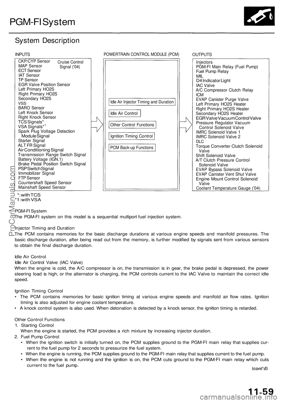
System Descriptio n
INPUTSPOWERTRAI N CONTRO L MODUL E (PCM )OUTPUT S
CKP/CYP Senso r
Cruise
Control
Signal ('04)MA P Senso rECT Senso rIAT Senso rTP Senso rEGR Valv e Positio n Senso rLeft Primar y HO2 SRight Primar y HO2 SSecondar y HO2 SVSSBAR O Senso rLeft Knoc k Senso rRight Knoc k Senso rTCS Signals *VSA Signals*1
Spar k Plu g Voltag e Detectio nModule Signa lStarte r Signa lALT F R Signa lAir Conditionin g Signa lTransmissio n Rang e Switc h Signa lBattery Voltag e (IGN.1 )Brake Peda l Positio n Switc h Signa lPSP Switc h Signa lImmobilize r Signa lFTP Senso rCountershaf t Spee d Senso rMainshaf t Spee d Senso r
Idle Ai r Injecto r Timin g an d Duratio n
Other Contro l Function s
Ignition Timin g Contro l
PCM Back-u p Function s
InjectorsPGM-FI Mai n Rela y (Fue l Pump )Fuel Pum p Rela yMILD4 Indicato r Ligh tIAC Valv eA/C Compresso r Clutc h Rela yICMEVA P Caniste r Purg e Valv eLeft Primar y HO2 S Heate rRight Primar y HO2 S Heate rSecondar y HO2 S Heate rEGR Valv e Vacuu m Contro l Valv ePressur e Regulato r Vacuu mControl Solenoi d Valv eIMRC Solenoi d Valv e 1IMR C Solenoi d Valv e 2DL CTorqu e Converte r Clutc h Solenoi dValveShift Solenoi d Valv eA/T Clutc h Pressur e Contro lSolenoid Valv eEVAP Bypas s Solenoi d Valv eEVAP Caniste r Ven t Shu t Valv eEngin e Moun t Contro l Solenoi dValve
PGM-F I Syste m
Th e PGM-F I syste m o n thi s mode l i s a sequentia l multipor t fue l injectio n system .
Injecto r Timin g an d Duratio n
Th e PC M contain s memorie s fo r th e basi c discharg e duration s a t variou s engin e speed s an d manifol d pressures . Th e
basi c discharg e duration , afte r bein g rea d ou t fro m th e memory , i s furthe r modifie d b y signal s sen t fro m variou s sensor s
t o obtai n th e fina l discharg e duration .
Idl e Ai r Contro l
Idl e Ai r Contro l Valv e (IA C Valve )
Whe n th e engin e i s cold , th e A/ C compresso r i s on , th e transmissio n i s i n gear , th e brak e peda l i s depressed , th e powe r
steerin g loa d i s high , o r th e alternato r i s charging , th e PC M control s curren t t o th e IA C Valv e t o maintai n th e correc t idl e
speed .
Ignition Timin g Contro l
• Th e PC M contain s memorie s fo r basi c ignitio n timin g a t variou s engin e speed s an d manifol d ai r flo w rates . Ignitio n
timin g i s als o adjuste d fo r engin e coolan t temperature .
• A knoc k contro l syste m is als o used . Whe n detonatio n i s detecte d b y a knoc k sensor , th e ignitio n timin g is retarded .
Othe r Contro l Function s
1 . Startin g Contro l
Whe n th e engin e is started , th e PC M provide s a ric h mixtur e b y increasin g injecto r duration .
2 . Fue l Pum p Contro l
• Whe n th e ignitio n switc h i s initiall y turne d on , th e PC M supplie s groun d t o th e PGM-F I mai n rela y tha t supplie s cur -
ren t t o th e fue l pum p fo r 2 second s t o pressuriz e th e fue l system .
• Whe n th e engin e is running , th e PC M supplie s groun d to th e PGM-F I mai n rela y tha t supplie s current to th e fue l pump .
• Whe n th e engin e is no t runnin g an d th e ignitio n i s on , th e PC M cut s groun d t o th e PGM-F I mai n rela y whic h cut s
curren t t o th e fue l pump .
*: wit h TC S*1: wit h VS A
Idle Ai r Contro l
Coolant Temperature Gauge ('04)
ProCarManuals.com
Page 609 of 1954
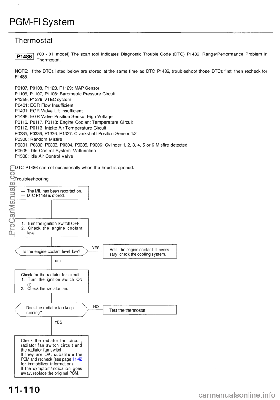
PGM-FI Syste m
NOTE: I f th e DTC s liste d belo w ar e store d a t th e sam e tim e a s DT C P1486 , troubleshoo t thos e DTC s first , the n rechec k fo r
P1486 .
P0107 , P0108 , P1128 , P1129 : MA P Senso r
P1106 , P1107 , P1108 : Barometri c Pressur e Circui t
P1259 , P1279 : VTE C syste m
P0401 : EG R Flo w Insufficien t
P1491 : EG R Valv e Lif t Insufficien t
P1498 : EG R Valv e Positio n Senso r Hig h Voltag e
P0116 , P0117 , P0118 : Engin e Coolan t Temperatur e Circui t
P0112, P0113 : Intak e Ai r Temperatur e Circui t
P0335 , P0336 , P1336 , P1337 : Crankshaf t Positio n Senso r 1/ 2
P0300 : Rando m Misfir e
P0301 , P0302 , P0303 , P0304 , P0305 , P0306 : Cylinde r 1 , 2 , 3 , 4 , 5 or 6 Misfir e detected .
P0505 : Idl e Contro l Syste m Malfunctio n
P1508 : Idl e Ai r Contro l Valv e
DT C P148 6 ca n se t occasionall y whe n th e hoo d i s opened .
— Th e MI L ha s bee n reporte d on .
— DT C P148 6 is stored .
1. Tur n th e ignitio n Switc h OFF .2. Chec k th e engin e coolan t
level .
I s th e engin e coolan t leve l low ?
Doe s th e radiato r fa n kee p
running ?
YES
Chec k th e radiato r fa n circuit ,
radiato r fa n switc h circui t an d
th e radiato r fa n switch .
I t the y ar e OK , substitut e th e
PC M an d rechec k (se e pag e 11-42
fo r immobilize r information) .
I f th e symptom/indicatio n goe s
away , replac e th e origina l PCM . Refil
l th e engin e coolant . I f neces -
sary , chec k th e coolin g system .
Tes t th e thermostat .
NO
N
O
YE S
Chec k fo r th e radiato r fo r circuit :
1 . Tur n th e ignitio n switc h O N
(II).2. Chec k th e radiato r fan .
Troubleshootin g
('00 - 0 1 model ) Th e sca n too l indicate s Diagnosti c Troubl e Cod e (DTC ) P1486 : Range/Performanc e Proble m in
Thermostat .
Thermostat
ProCarManuals.com
Page 656 of 1954
Intake Air System
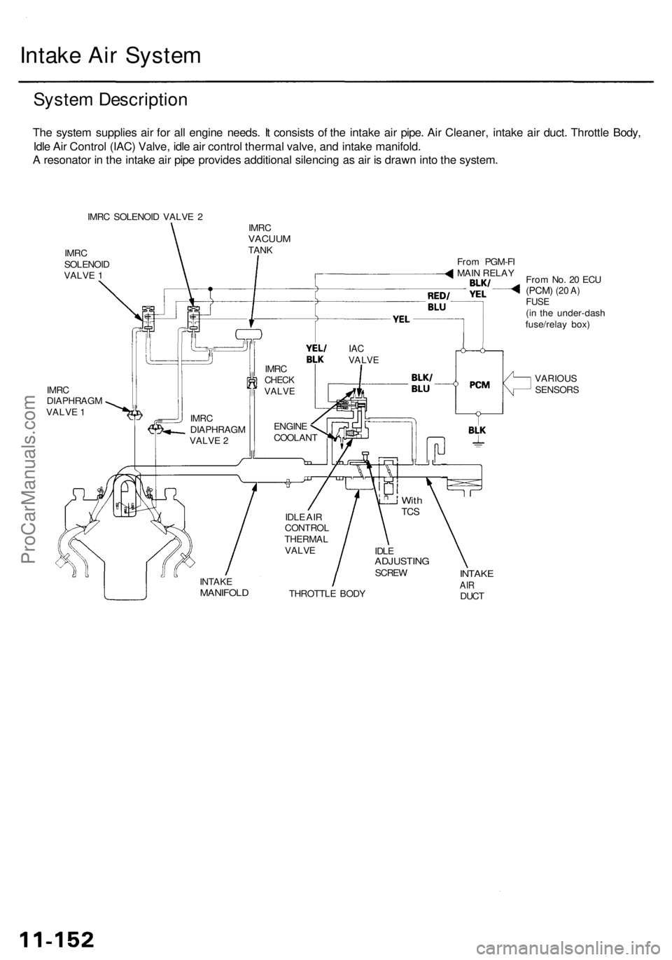
System Description
The system supplies air for all engine needs. It consists of the intake air pipe. Air Cleaner, intake air duct. Throttle Body,
Idle Air Control (IAC) Valve, idle air control thermal valve, and intake manifold.
A resonator in the intake air pipe provides additional silencing as air is drawn into the system.
IMRC SOLENOID VALVE 2
IMRC
SOLENOID
VALVE 1
IMRC
VACUUM
TANK
From No. 20 ECU
(PCM)
(20 A)
FUSE
(in the under-dash
fuse/relay box)
IMRC
DIAPHRAGM
VALVE 1
VARIOUS
SENSORS
THROTTLE BODY
INTAKE
AIR
DUCT
INTAKE
MANIFOLD
IDLE
ADJUSTING
SCREW
With
TCS
IDLE AIR
CONTROL
THERMAL
VALVE
IAC
VALVE
From PGM-FI
MAIN RELAY
IMRC
DIAPHRAGM
VALVE 2
IMRC
CHECK
VALVE
ENGINE
COOLANTProCarManuals.com
Page 728 of 1954
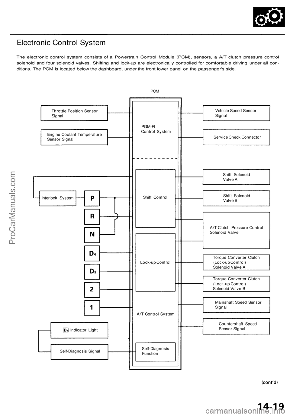
Electronic Control System
The electronic control system consists of a Powertrain Control Module (PCM), sensors, a A/T clutch pressure control
solenoid and four solenoid valves. Shifting and lock-up are electronically controlled for comfortable driving under all con-
ditions. The PCM is located below the dashboard, under the front lower panel on the passenger's side.
PCM
Throttle Position Sensor
Signal
Engine Coolant Temperature
Sensor Signal
Indicator Light
Self-Diagnosis Signal
PGM-FI
Control System
Shift Control
Lock-up Control
A/T Control System
Self-Diagnosis
Function
Vehicle Speed Sensor
Signal
Service Check Connector
Shift Solenoid
Valve A
Shift Solenoid
Valve B
A/T Clutch Pressure Control
Solenoid Valve
Torque Converter Clutch
(Lock-up Control)
Solenoid Valve A
Torque Converter Clutch
(Lock-up Control)
Solenoid Valve B
Mainshaft Speed Sensor
Signal
Countershaft Speed
Sensor Signal
Interlock SystemProCarManuals.com
Page 730 of 1954

Grade Logic Control System
How it works:
The PCM compares actual driving conditions with driving conditions memorized in the PCM, based on the input from the
vehicle speed sensor, throttle position sensor, engine coolant temperature sensor, barometric pressure sensor, brake
pedal position switch signal and shift lever position signal, to control shifting while a vehicle is ascending or descending a
slope.ProCarManuals.com
Page 1195 of 1954
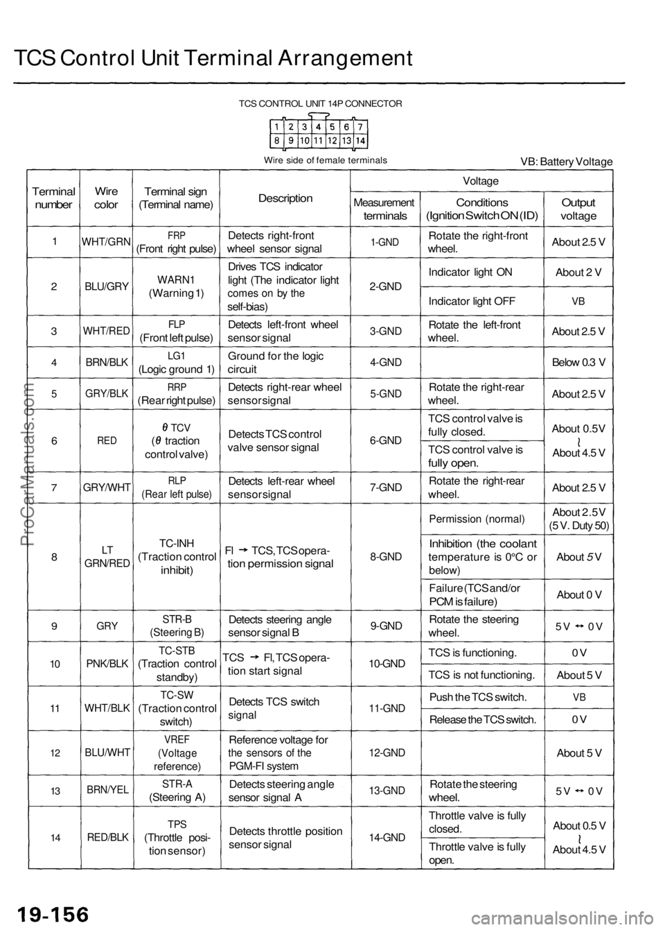
TCS Control Unit Terminal Arrangement
TCS CONTROL UNIT 14P CONNECTOR
Wire side of female terminals
VB: Battery Voltage
Terminal
number
1
2
3
4
5
6
7
8
9
10
11
12
13
14
Wire
color
WHT/GRN
BLU/GRY
WHT/RED
BRN/BLK
GRY/BLK
RED
GRY/WHT
LT
GRN/RED
GRY
PNK/BLK
WHT/BLK
BLU/WHT
BRN/YEL
RED/BLK
Terminal sign
(Terminal name)
FRP
(Front right pulse)
WARN1
(Warning 1)
FLP
(Front left pulse)
LG1
(Logic ground 1)
RRP
(Rear right pulse)
TCV
( traction
control valve)
RLP
(Rear left pulse)
TC-INH
(Traction control
inhibit)
STR-B
(Steering B)
TC-STB
(Traction control
standby)
TC-SW
(Traction control
switch)
VREF
(Voltage
reference)
STR-A
(Steering A)
TPS
(Throttle posi-
tion sensor)
Description
Detects right-front
wheel sensor signal
Drives TCS indicator
light (The indicator light
comes on by the
self-bias)
Detects left-front wheel
sensor signal
Ground for the logic
circuit
Detects right-rear wheel
sensor signal
Detects TCS control
valve sensor signal
Detects left-rear wheel
sensor signal
Fl TCS, TCS opera-
tion permission signal
Detects steering angle
sensor signal B
TCS Fl, TCS opera-
tion start signal
Detects TCS switch
signal
Reference voltage for
the sensors of the
PGM-FI system
Detects steering angle
sensor signal A
Detects throttle position
sensor signal
Voltage
Measurement
terminals
1-GND
2-GND
3-GND
4-GND
5-GND
6-GND
7-GND
8-GND
9-GND
10-GND
11-GND
12-GND
13-GND
14-GND
Conditions
(Ignition Switch ON (ID)
Rotate the right-front
wheel.
Indicator light ON
Indicator light OFF
Rotate the left-front
wheel.
Rotate the right-rear
wheel.
TCS control valve is
fully closed.
TCS control valve is
fully open.
Rotate the right-rear
wheel.
Permission (normal)
Inhibition (the coolant
temperature is 0°C or
below)
Failure (TCS and/or
PCM is failure)
Rotate the steering
wheel.
TCS is functioning.
TCS is not functioning.
Push the TCS switch.
Release the TCS switch.
Rotate the steering
wheel.
Throttle valve is fully
closed.
Throttle valve is fully
open.
Output
voltage
About 2.5 V
About 2 V
VB
About 2.5 V
Below 0.3 V
About 2.5 V
About 0.5V
About 4.5 V
About 2.5 V
About 2.5V
(5 V. Duty 50)
About 5 V
About 0 V
5V 0V
0V
About 5 V
VB
0V
About 5 V
5V 0V
About 0.5 V
About 4.5 VProCarManuals.com
Page 1197 of 1954

Troubleshooting Precautions
1. In any of these cases, the TCS indicator light may come on or stay on even the TCS system is normal.
The coolant temperature is 32°F (0°C) or below.
The parking brake is applied for more than 30 seconds while the vehicle is being driven.
The tires are not inflated to the specified pressure.
The wheel sensor signal is interrupted during driving at speeds of 6 mph (10 km/h) or above due to, for example, a
vehicle spinning.
The MAP sensor, the coolant temperature sensor, the ICM or the atmospheric pressure sensor system of the PGM-FI
system is faulty.
2. TCS does not function when the TCS indicator light is ON.
3. When both the TCS indicator light and the MIL are ON, troubleshoot the PGM-FI system first.
4. When both the TCS indicator light and the ABS indicator light are ON, troubleshoot the ABS first.
5. The DTC 4-9 (ABS down) is memorized when the ABS control unit cannot output the wheel speed signal due to, for
example, a missing or blown ABS B2 (15 A) fuse. If you fail to erase the DTC of the TCS after troubleshooting the ABS,
the DTC remains in the TCS control unit memory. Therefore, be sure to test-drive the vehicle, and check the TCS indica-
tor light before starting to troubleshoot the TCS.ProCarManuals.com