jump cable ACURA RL KA9 1996 Service Repair Manual
[x] Cancel search | Manufacturer: ACURA, Model Year: 1996, Model line: RL KA9, Model: ACURA RL KA9 1996Pages: 1954, PDF Size: 61.44 MB
Page 264 of 1954

+
BODY
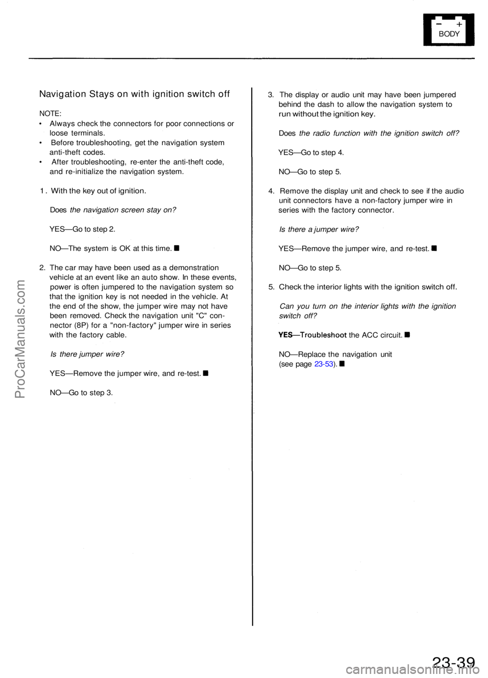
Navigatio n Stay s o n wit h ignitio n switc h of f
NOTE :
• Alway s chec k th e connector s fo r poo r connection s o r
loos e terminals .
• Befor e troubleshooting , ge t th e navigatio n syste m
anti-thef t codes .
• Afte r troubleshooting , re-ente r th e anti-thef t code ,
an d re-initializ e th e navigatio n system .
1. Wit h th e ke y ou t o f ignition .
Does the navigation screen stay on?
YES—G o to ste p 2 .
NO—Th e syste m is O K a t thi s time .
2 . Th e ca r ma y hav e bee n use d a s a demonstratio n
vehicl e a t a n even t lik e a n aut o show . I n thes e events ,
powe r i s ofte n jumpere d t o th e navigatio n syste m s o
tha t th e ignitio n ke y i s no t neede d i n th e vehicle . A t
th e en d o f th e show , th e jumpe r wir e ma y no t hav e
bee n removed . Chec k th e navigatio n uni t "C " con -
necto r (8P ) fo r a "non-factory " jumpe r wir e in serie s
wit h th e factor y cable .
Is there jumper wire?
YES—Remov e th e jumpe r wire , an d re-test .
NO—G o t o ste p 3 . 3
. Th e displa y o r audi o uni t ma y hav e bee n jumpere d
behin d th e das h t o allo w th e navigatio n syste m to
ru n withou t th e ignitio n key .
Doe s the radio function with the ignition switch off?
YES—G o to ste p 4 .
NO—G o t o ste p 5 .
4 . Remov e th e displa y uni t an d chec k t o se e if th e audi o
uni t connector s hav e a non-factor y jumpe r wir e i n
serie s wit h th e factor y connector .
Is there a jumper wire?
YES—Remov e th e jumpe r wire , an d re-test .
NO—G o to ste p 5 .
5. Chec k th e interio r light s wit h th e ignitio n switc h off .
Can you turn on the interior lights with the ignition
switch off?
YES—Troubleshoo t the AC C circuit .
NO—Replac e th e navigatio n uni t
(se e pag e 23-53 ).
23-3 9
ProCarManuals.com
Page 325 of 1954

Starter Tes t
NOTE : Th e ai r temperatur e mus t b e betwee n 5 9 an d
100° F (1 5 an d 38°C ) befor e testing .
Recommende d Procedure :
Use a starte r syste m tester .
Connec t an d operat e th e equipmen t i n accordanc e
wit h th e manufacturer' s instructions .
Tes t an d troubleshoo t a s described .
Alternat e Procedure :
Use followin g equipment :
— Ammeter , 0 - 40 0 A
— Voltmeter , 0 - 2 0 V (accurat e withi n 0. 1 volt )
— Tachometer , 0 - 1,20 0 rp m
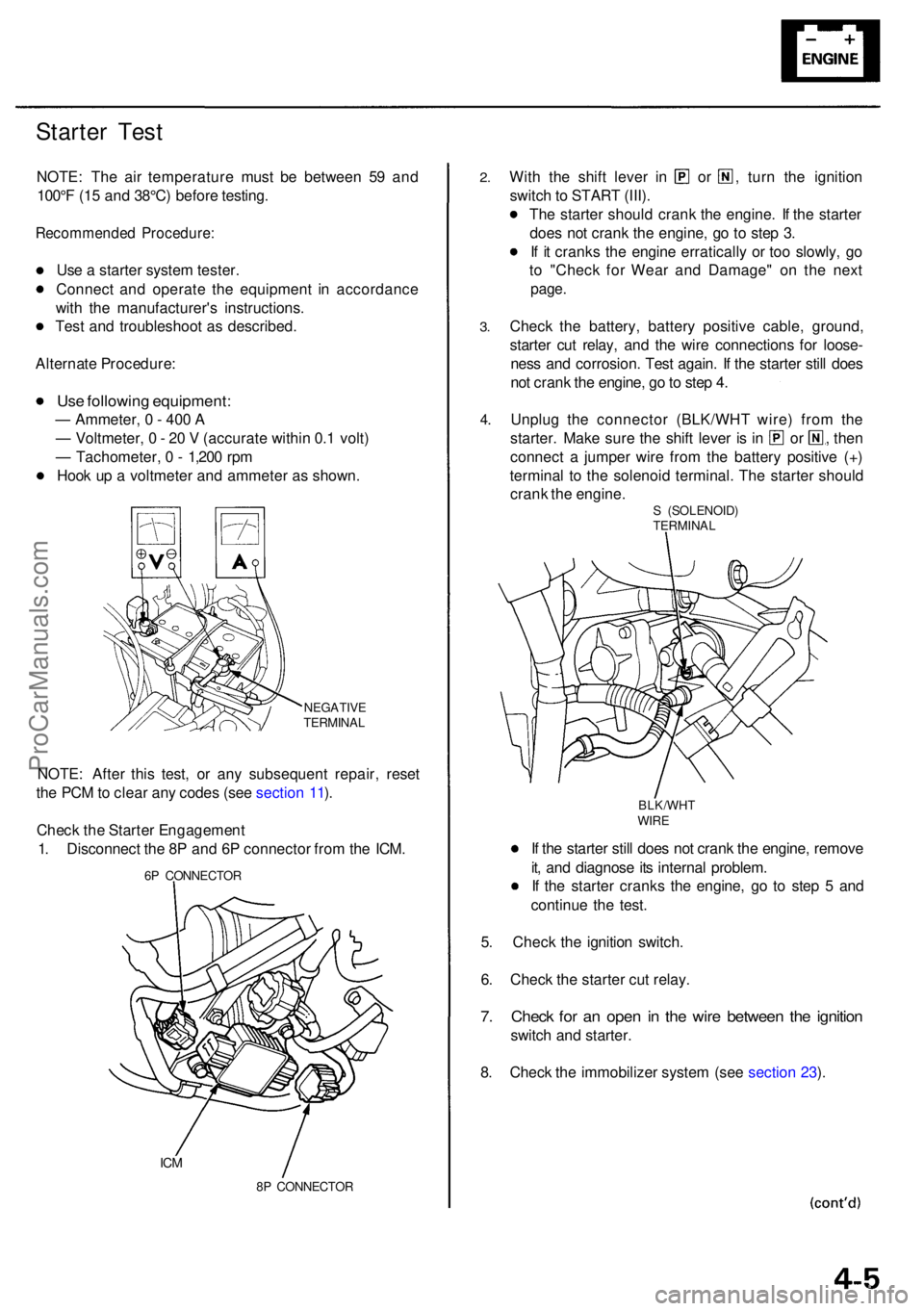
Hoo k u p a voltmete r an d ammete r a s shown .
NEGATIV E
TERMINA L
NOTE: Afte r thi s test , o r an y subsequen t repair , rese t
th e PC M to clea r an y code s (se e sectio n 11 ).
Chec k th e Starte r Engagemen t
1 . Disconnec t th e 8 P an d 6 P connecto r fro m th e ICM .
6P CONNECTO R
ICM
8P CONNECTO R
2.
3.
Wit h th e shif t leve r i n o r , turn th e ignitio n
switc h to STAR T (III) .
Th e starte r shoul d cran k th e engine . I f th e starte r
doe s no t cran k th e engine , g o t o ste p 3 .
I f i t crank s th e engin e erraticall y o r to o slowly , g o
t o "Chec k fo r Wea r an d Damage " o n th e nex t
page .
Chec k th e battery , batter y positiv e cable , ground ,
starte r cu t relay , an d th e wir e connection s fo r loose -
nes s an d corrosion . Tes t again . I f th e starte r stil l doe s
no t cran k th e engine , g o to ste p 4 .
Unplu g th e connecto r (BLK/WH T wire ) fro m th e
starter . Mak e sur e th e shif t leve r i s i n o r , then
connec t a jumpe r wir e fro m th e batter y positiv e (+ )
termina l t o th e solenoi d terminal . Th e starte r shoul d
cran k th e engine .
S (SOLENOID )
TERMINA L
BLK/WH T
WIRE
If th e starte r stil l doe s no t cran k th e engine , remov e
it , an d diagnos e it s interna l problem .
I f th e starte r crank s th e engine , g o t o ste p 5 an d
continu e th e test .
5 . Chec k th e ignitio n switch .
6 . Chec k th e starte r cu t relay .
7. Chec k fo r a n ope n i n th e wir e betwee n th e ignitio n
switch an d starter .
8 . Chec k th e immobilize r syste m (se e sectio n 23 ).
4 .
ProCarManuals.com
Page 1846 of 1954

DTC 9- 1 o r N o Cod e
CAUTION : Wheneve r th e ignitio n switc h is O N (II) , o r ha s
bee n turne d OF F fo r les s tha n 3 minutes , b e carefu l no t
to bum p th e SR S unit ; th e airbag s coul d accidentall y
deploy an d caus e damag e o r injuries .
NOTE: Th e PC M memor y mus t b e rese t afte r reconnect -
ing th e batter y (se e pag e 11-125 ).
Troubleshootin g - '9 6 - 9 8 Model s
Try t o reproduc e th e SR S indicato r light :
1 . Eras e th e DT C memor y (se e pag e 24-37 ).
2 . Tur n th e ignitio n switc h O N (II) , an d chec k tha t th e SR S
indicato r ligh t come s o n fo r abou t 6 second s an d the n
goe s off .
Intermitten t failure , syste m is O K a t thi s time . Se eTroubleshootin g Intermitten t Failure s o n pag e 24-37 .
Chec k th e SR S uni t (1) :
1 . Tur n th e ignitio n switc h OFF .
2. Rea d th e DT C (se e pag e 24-35 ).
T o pag e 24-7 7
Chec k th e SR S uni t (2) :
1 . Mak e sur e yo u hav e th e anti-thef t cod e fo r th e radio ,
the n writ e dow n th e frequencie s fo r th e radio' s prese t
buttons .
2 . Disconnec t th e batter y negativ e cable , the n disconnec t
th e positiv e cable , an d wai t fo r 3 minutes .
3 . Disconnec t th e driver' s an d fron t passenger' s airba g con -
nectors , the n disconnec t th e driver' s an d fron t passen -
ger' s sea t bel t tensione r connector s (se e pag e 24-33 ).
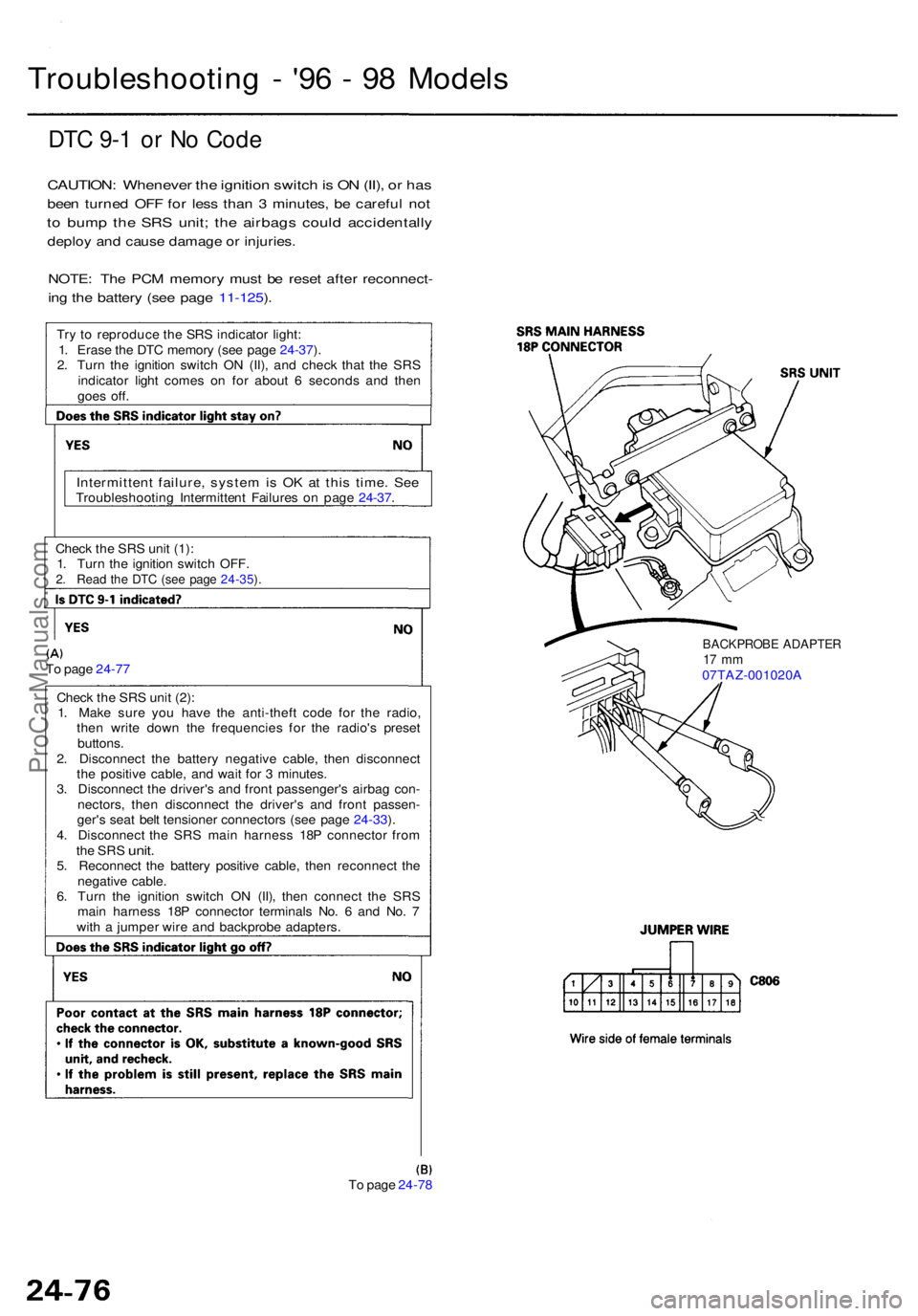
4 . Disconnec t th e SR S mai n harnes s 18 P connecto r fro m
the SR S unit .5. Reconnec t th e batter y positiv e cable , the n reconnec t th e
negativ e cable .
6 . Tur n th e ignitio n switc h O N (II) , the n connec t th e SR S
mai n harnes s 18 P connecto r terminal s No . 6 an d No . 7
wit h a jumpe r wir e an d backprob e adapters .
To pag e 24-7 8
BACKPROB E ADAPTE R17 m m07TAZ-001020 A
ProCarManuals.com