dashboard ACURA RL KA9 1996 Service User Guide
[x] Cancel search | Manufacturer: ACURA, Model Year: 1996, Model line: RL KA9, Model: ACURA RL KA9 1996Pages: 1954, PDF Size: 61.44 MB
Page 1475 of 1954
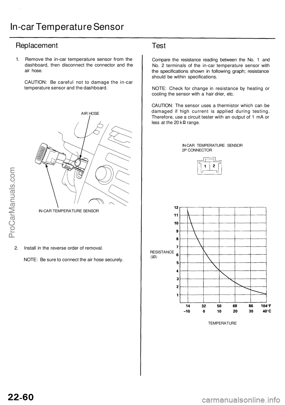
In-car Temperatur e Senso r
Replacemen t
1. Remov e th e in-ca r temperatur e senso r fro m th e
dashboard , the n disconnec t th e connecto r an d th e
ai r hose .
CAUTION : B e carefu l no t t o damag e th e in-ca r
temperatur e senso r an d th e dashboard .
AIR HOS E
IN-CA R TEMPERATUR E SENSO R
2. Instal l i n th e revers e orde r o f removal .
NOTE : B e sur e to connec t th e ai r hos e securely .
Test
Compar e th e resistanc e readin g betwee n th e No . 1 an d
No . 2 terminal s o f th e in-ca r temperatur e senso r wit h
the specification s show n i n followin g graph ; resistanc e
should b e withi n specifications .
NOTE : Chec k fo r chang e i n resistanc e b y heatin g o r
coolin g th e senso r wit h a hai r drier , etc .
CAUTION : Th e senso r use s a thermisto r whic h ca n b e
damage d i f hig h curren t i s applie d durin g testing .
Therefore , us e a circui t teste r wit h a n outpu t o f 1 m A o r
les s a t th e 2 0 k range .
IN-CAR TEMPERATUR E SENSO R
2 P CONNECTO R
RESISTANC E
(k )
TEMPERATUR E
ProCarManuals.com
Page 1477 of 1954
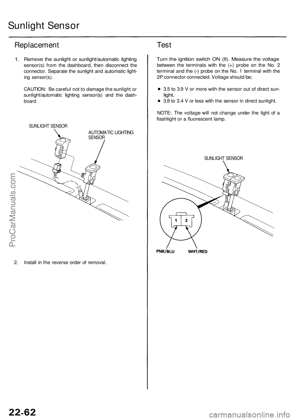
Sunlight Senso r
Replacemen t
Remove th e sunligh t o r sunlight/automati c lightin g
sensor(s ) fro m th e dashboard , the n disconnec t th e
connector . Separat e th e sunligh t an d automati c light -
ing sensor(s) .
CAUTION: B e carefu l no t t o damag e th e sunligh t o r
sunlight/automati c lightin g sensor(s ) an d th e dash -
board .
SUNLIGH T SENSO R
AUTOMATI C LIGHTIN GSENSOR
2. Instal l i n th e revers e orde r o f removal .
Test
Turn th e ignitio n switc h O N (II) . Measur e th e voltag e
betwee n th e terminal s wit h th e (+ ) prob e o n th e No . 2
termina l an d th e (- ) prob e o n th e No . 1 termina l wit h th e
2 P connecto r connected . Voltag e shoul d be ;
3. 5 to 3. 9 V or mor e wit h th e senso r ou t o f direc t sun -
light.
3.8 to 3. 4 V or les s wit h th e senso r i n direc t sunlight .
NOTE : Th e voltag e wil l no t chang e unde r th e ligh t o f a
flashligh t o r a fluorescen t lamp .
SUNLIGH T SENSO R
ProCarManuals.com
Page 1541 of 1954
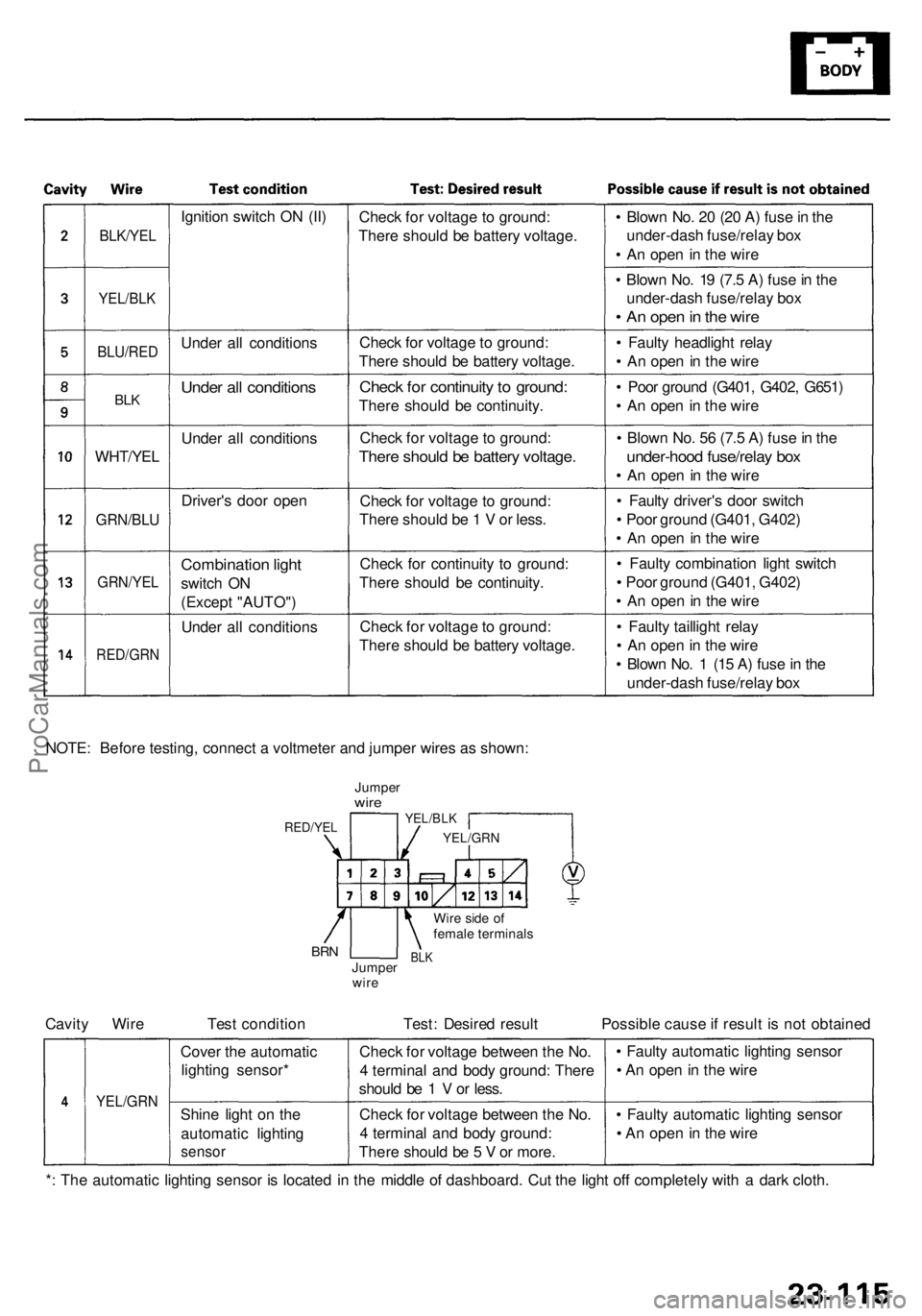
BLK/YEL
YEL/BLK
BLU/RE D
BLK
WHT/YE L
GRN/BLU
GRN/YE L
RED/GR N
Ignition switc h O N (II )
Unde r al l condition s
Under al l condition s
Under al l condition s
Driver' s doo r ope n
Combinatio n ligh t
switc h O N
(Excep t "AUTO" )
Unde r al l condition sChec
k fo r voltag e to ground :
Ther e shoul d b e batter y voltage .
Chec k fo r voltag e to ground:
Ther e shoul d b e batter y voltage .
Check fo r continuit y to ground :
There shoul d b e continuity .
Chec k fo r voltag e to ground :
There shoul d b e batter y voltage .
Check fo r voltag e t o ground :
Ther e shoul d b e 1 V or less .
Chec k fo r continuit y t o ground :
Ther e shoul d b e continuity .
Chec k fo r voltag e to ground :
Ther e shoul d b e batter y voltage .•
Blow n No . 2 0 (2 0 A ) fus e in th e
under-das h fuse/rela y bo x
• A n ope n in th e wir e
• Blow n No . 1 9 (7. 5 A ) fus e in th e
under-das h fuse/rela y bo x
• A n ope n in th e wir e
• Fault y headligh t rela y
• A n ope n in th e wir e
• Poo r groun d (G401 , G402 , G651 )
• A n ope n in th e wir e
• Blow n No . 5 6 (7. 5 A ) fus e in th e
under-hoo d fuse/rela y bo x
• A n ope n in th e wir e
• Fault y driver' s doo r switc h
• Poo r groun d (G401 , G402 )
• A n ope n in th e wir e
• Fault y combinatio n ligh t switc h
• Poo r ground (G401, G402 )
• A n ope n in th e wir e
• Fault y tailligh t rela y
• A n ope n in th e wir e
• Blow n No . 1 (1 5 A ) fus e in th e
under-das h fuse/rela y bo x
NOTE : Befor e testing , connec t a voltmete r an d jumpe r wire s a s shown :
JumperwireYEL/BL K
YEL/GR N
Wire sid e o f
femal e terminal s
BLKJumpe r
wir eBRN
RED/YE L
Cavity Wir e Tes t conditio n Test : Desire d resul t Possibl e caus e if resul t i s no t obtaine d
YEL/GR N
Cover th e automati c
lightin g sensor *
Shin e ligh t o n th e
automati c lightin g
sensor
Check fo r voltag e betwee n th e No .
4 termina l an d bod y ground : Ther e
shoul d b e 1 V or less .
Chec k fo r voltag e betwee n th e No .
4 termina l an d bod y ground :
Ther e shoul d b e 5 V or more . •
Fault y automati c lightin g senso r
• A n ope n in th e wir e
• Fault y automati c lightin g senso r
• A n ope n in th e wir e
* : Th e automati c lightin g senso r i s locate d i n th e middl e o f dashboard . Cu t th e ligh t of f completel y wit h a dar k cloth .
ProCarManuals.com
Page 1598 of 1954
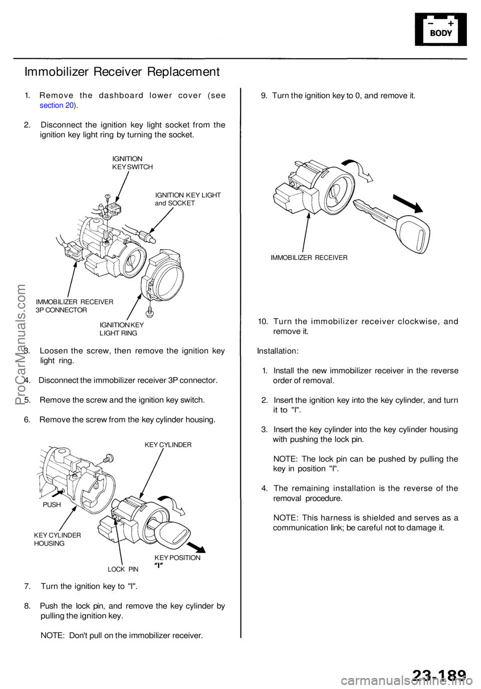
Immobilizer Receive r Replacemen t
1. Remove the dashboard lower cover (see
section 20 ).
2 . Disconnec t th e ignitio n ke y ligh t socke t fro m th e
ignitio n ke y ligh t rin g b y turnin g th e socket .
IGNITIO NKEY SWITC H
IGNITIO N KE Y LIGH T
and SOCKE T
9. Tur n th e ignitio n ke y to 0, an d remov e it .
IMMOBILIZE R RECEIVE R
10. Tur n th e immobilize r receive r clockwise , an d
remov e it .
Installation :
1. Instal l th e ne w immobilize r receive r i n th e revers e
orde r o f removal .
2 . Inser t th e ignitio n ke y int o th e ke y cylinder , an d tur n
it t o "I" .
3. Inser t th e ke y cylinde r int o th e ke y cylinde r housin g
wit h pushin g th e loc k pin .
NOTE : Th e loc k pi n ca n b e pushe d b y pullin g th e
ke y i n positio n "I" .
4 . Th e remainin g installatio n i s th e revers e o f th e
remova l procedure .
NOTE : Thi s harnes s i s shielde d an d serve s a s a
communicatio n link ; b e carefu l no t t o damag e it .
7 . Tur n th e ignitio n ke y t o "I" .
8 . Pus h th e loc k pin , an d remov e th e ke y cylinde r b y
pullin g th e ignitio n key .
NOTE : Don' t pul l o n th e immobilize r receiver .
3
. Loose n th e screw , the n remov e th e ignitio n ke y
ligh t ring .
4 . Disconnec t th e immobilize r receive r 3 P connector .
5 . Remov e th e scre w an d th e ignitio n ke y switch .
6 . Remov e th e scre w fro m th e ke y cylinde r housing .
IMMOBILIZE R RECEIVE R3P CONNECTO R
IGNITION KEYLIGH T RIN G
KEY CYLINDE RHOUSING
PUS
H
LOC K PI N
KEY POSITIO N
KEY CYLINDE R
ProCarManuals.com
Page 1657 of 1954
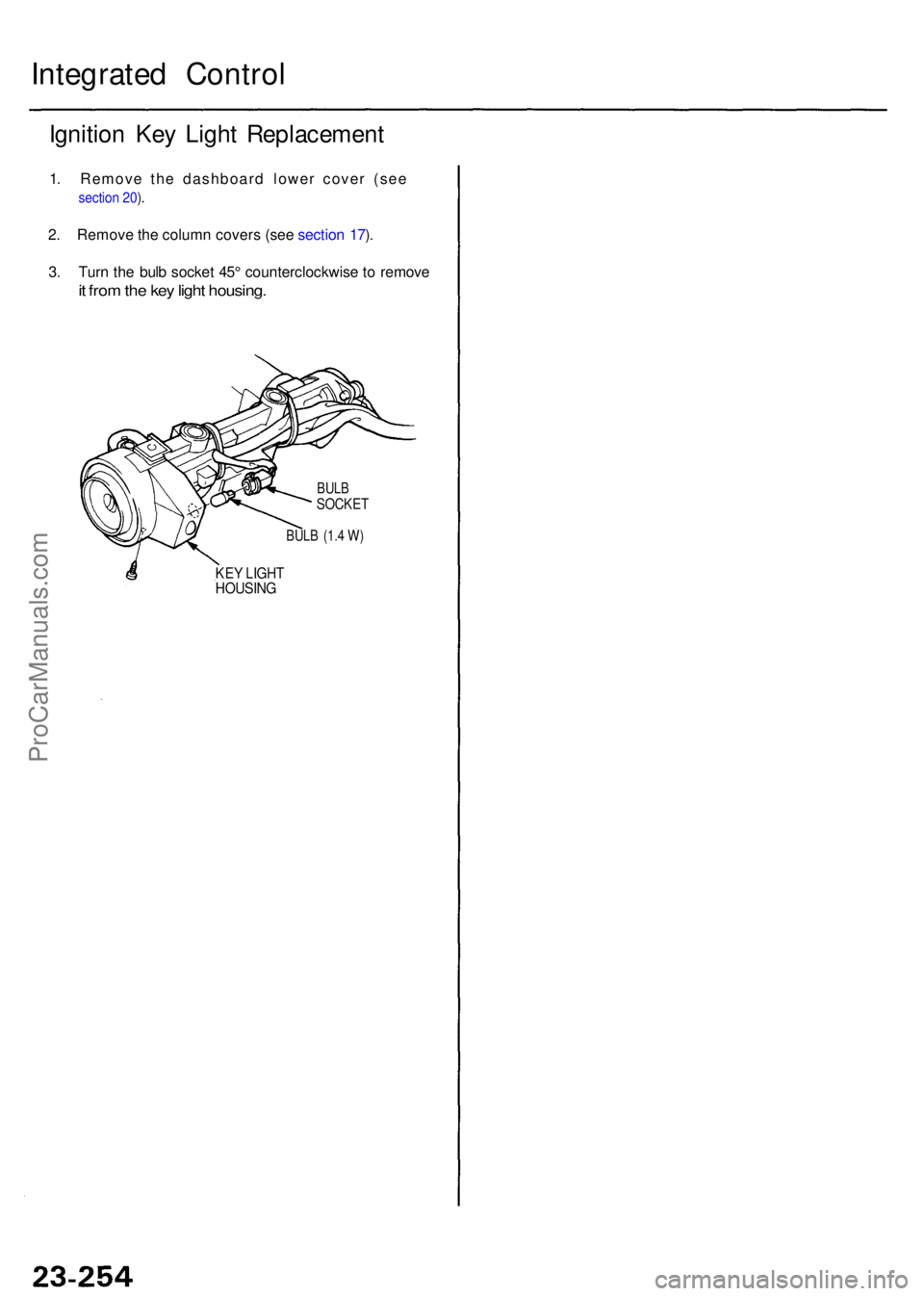
Integrated Contro l
Ignition Ke y Ligh t Replacemen t
1. Remove the dashboard lower cover (see
section 20 ).
2 . Remov e th e colum n cover s (se e sectio n 17 ).
3 . Tur n th e bul b socke t 45 ° counterclockwis e t o remov e
it fro m th e ke y ligh t housing .
BULB (1. 4 W )
KE Y LIGH THOUSIN G
BULBSOCKE T
ProCarManuals.com
Page 1796 of 1954
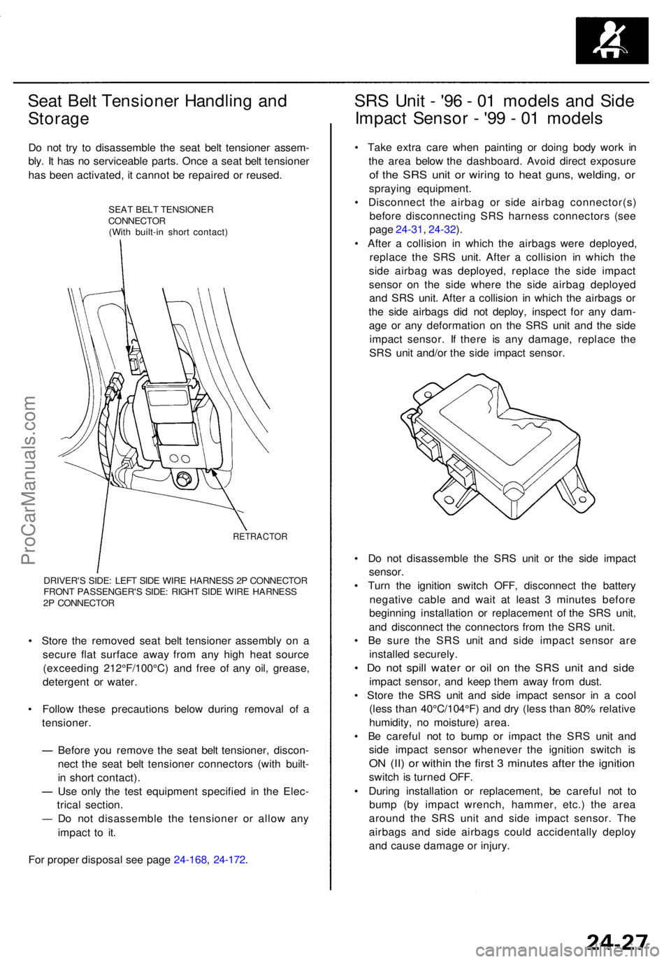
Seat Bel t Tensione r Handlin g an d
Storag e
Do no t tr y t o disassembl e th e sea t bel t tensione r assem -
bly . I t ha s n o serviceabl e parts . Onc e a sea t bel t tensione r
ha s bee n activated , i t canno t b e repaire d o r reused .
SEAT BEL T TENSIONE R
CONNECTO R
(Wit h built-i n shor t contact )
RETRACTO R
DRIVER'S SIDE : LEF T SID E WIR E HARNES S 2 P CONNECTO R
FRON T PASSENGER' S SIDE : RIGH T SID E WIR E HARNES S
2 P CONNECTO R
• Stor e th e remove d sea t bel t tensione r assembl y o n a
secur e fla t surfac e awa y fro m an y hig h hea t sourc e
(exceedin g 212°F/100°C ) an d fre e o f an y oil , grease ,
detergen t o r water .
• Follo w thes e precaution s belo w during remova l o f a
tensioner .
Befor e yo u remov e th e sea t bel t tensioner , discon -
nec t th e sea t bel t tensione r connector s (wit h built -
i n shor t contact) .
Us e onl y th e tes t equipmen t specifie d i n th e Elec -
trica l section .
D o no t disassembl e th e tensione r o r allo w an y
impac t t o it .
Fo r prope r disposa l se e pag e 24-168 , 24-172 .
SRS Uni t - '9 6 - 0 1 model s an d Sid e
Impac t Senso r - '9 9 - 0 1 model s
• Tak e extr a car e whe n paintin g o r doin g bod y wor k i n
th e are a belo w th e dashboard . Avoi d direc t exposur e
of th e SR S uni t o r wirin g t o hea t guns , welding , o r
sprayin g equipment .
• Disconnec t th e airba g o r sid e airba g connector(s )
befor e disconnectin g SR S harnes s connector s (se e
pag e 24-31 , 24-32 ).
• Afte r a collisio n i n whic h th e airbag s wer e deployed ,
replac e th e SR S unit . Afte r a collisio n i n whic h th e
sid e airba g wa s deployed , replac e th e sid e impac t
senso r o n th e sid e wher e th e sid e airba g deploye d
an d SR S unit . Afte r a collisio n i n whic h th e airbag s o r
th e sid e airbag s di d no t deploy , inspec t fo r an y dam -
ag e o r an y deformatio n o n th e SR S uni t an d th e sid e
impac t sensor . I f ther e i s an y damage , replac e th e
SR S uni t and/o r th e sid e impac t sensor .
• D o no t disassembl e th e SR S uni t o r th e sid e impac t
sensor .
• Tur n th e ignitio n switc h OFF , disconnec t th e batter y
negativ e cabl e an d wai t a t leas t 3 minute s befor e
beginnin g installatio n o r replacemen t o f th e SR S unit ,
an d disconnec t th e connector s fro m th e SR S unit .
• B e sur e th e SR S uni t an d sid e impac t senso r ar e
installe d securely .
• D o no t spil l wate r o r oi l o n th e SR S uni t an d sid e
impac t sensor , an d kee p the m awa y fro m dust .
• Stor e th e SR S uni t an d sid e impac t senso r i n a coo l
(les s tha n 40°C/104°F ) an d dr y (les s tha n 80 % relativ e
humidity , n o moisture ) area .
• B e carefu l no t t o bum p o r impac t th e SR S uni t an d
sid e impac t senso r wheneve r th e ignitio n switc h i s
ON (II ) o r withi n th e firs t 3 minute s afte r th e ignitio n
switch i s turne d OFF .
• Durin g installatio n o r replacement , b e carefu l no t t o
bum p (b y impac t wrench , hammer , etc. ) th e are a
aroun d th e SR S uni t an d sid e impac t sensor . Th e
airbag s an d sid e airbag s coul d accidentall y deplo y
an d caus e damag e o r injury .
ProCarManuals.com
Page 1810 of 1954
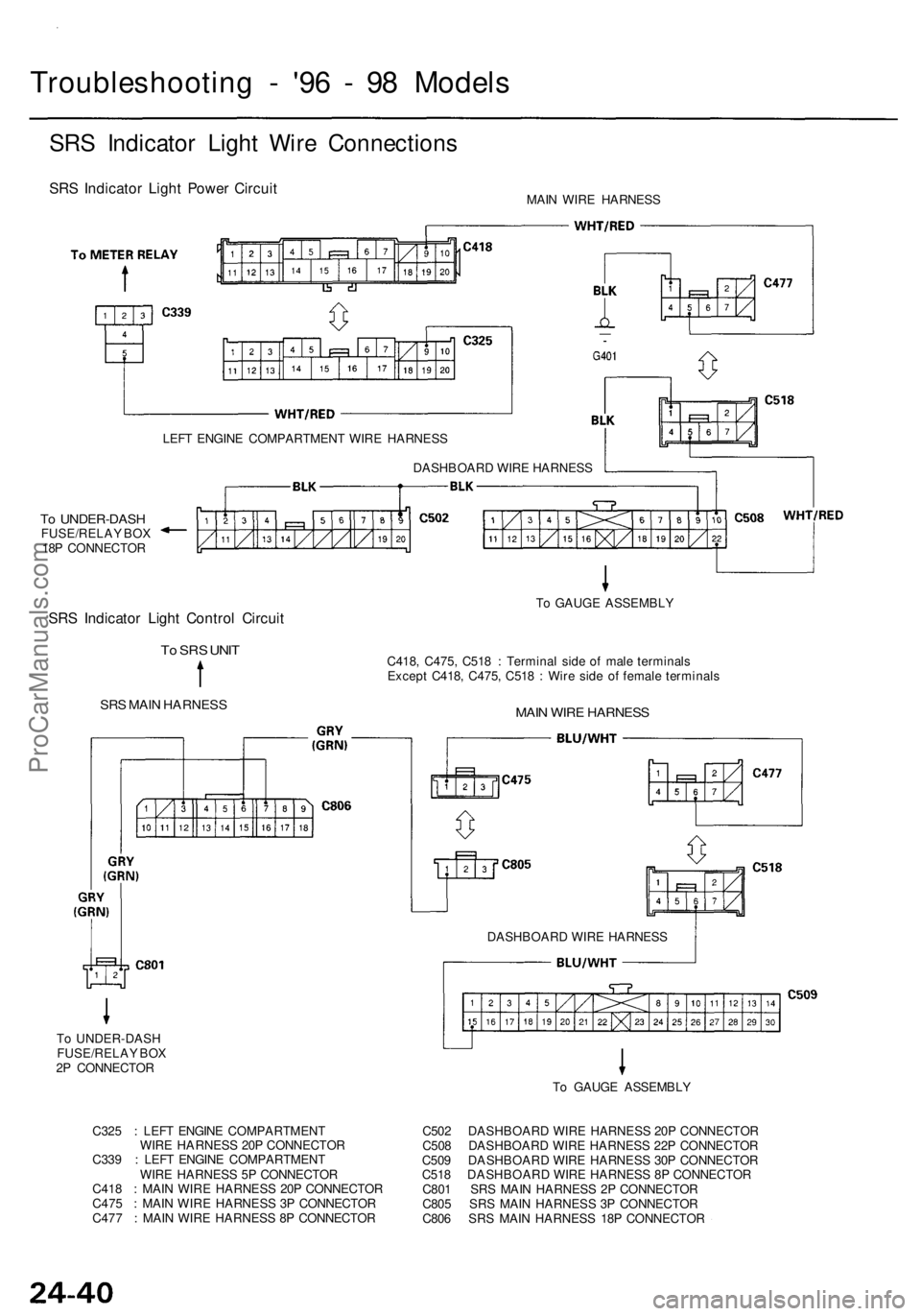
To UNDER-DASH
FUSE/RELAY BOX
2P CONNECTOR
Troubleshooting - '96 - 98 Models
SRS Indicator Light Wire Connections
SRS Indicator Light Power Circuit
MAIN WIRE HARNESS
LEFT ENGINE COMPARTMENT WIRE HARNESS
To UNDER-DASH
FUSE/RELAY BOX
18P CONNECTOR
SRS Indicator Light Control Circuit
To SRS UNIT
SRS MAIN HARNESS
C418, C475, C518 : Terminal side of male terminals
Except C418, C475, C518 : Wire side of female terminals
MAIN WIRE HARNESS
To GAUGE ASSEMBLY
DASHBOARD WIRE HARNESS
DASHBOARD WIRE HARNESS
To GAUGE ASSEMBLY
C325 : LEFT ENGINE COMPARTMENT
WIRE HARNESS 20P CONNECTOR
C339 : LEFT ENGINE COMPARTMENT
WIRE HARNESS 5P CONNECTOR
C418 : MAIN WIRE HARNESS 20P CONNECTOR
C475 : MAIN WIRE HARNESS 3P CONNECTOR
C477 : MAIN WIRE HARNESS 8P CONNECTOR
C502 DASHBOARD WIRE HARNESS 20P CONNECTOR
C508 DASHBOARD WIRE HARNESS 22P CONNECTOR
C509 DASHBOARD WIRE HARNESS 30P CONNECTOR
C518 DASHBOARD WIRE HARNESS 8P CONNECTOR
C801 SRS MAIN HARNESS 2P CONNECTOR
C805 SRS MAIN HARNESS 3P CONNECTOR
C806 SRS MAIN HARNESS 18P CONNECTORProCarManuals.com
Page 1812 of 1954
To pag e 24-4 3
Troubleshootin g - '9 6 - 9 8 Model s
The SR S Indicato r Ligh t Doesn' t Com e O n (cont'd )
From pag e 24-4 1 From pag e 24-4 1
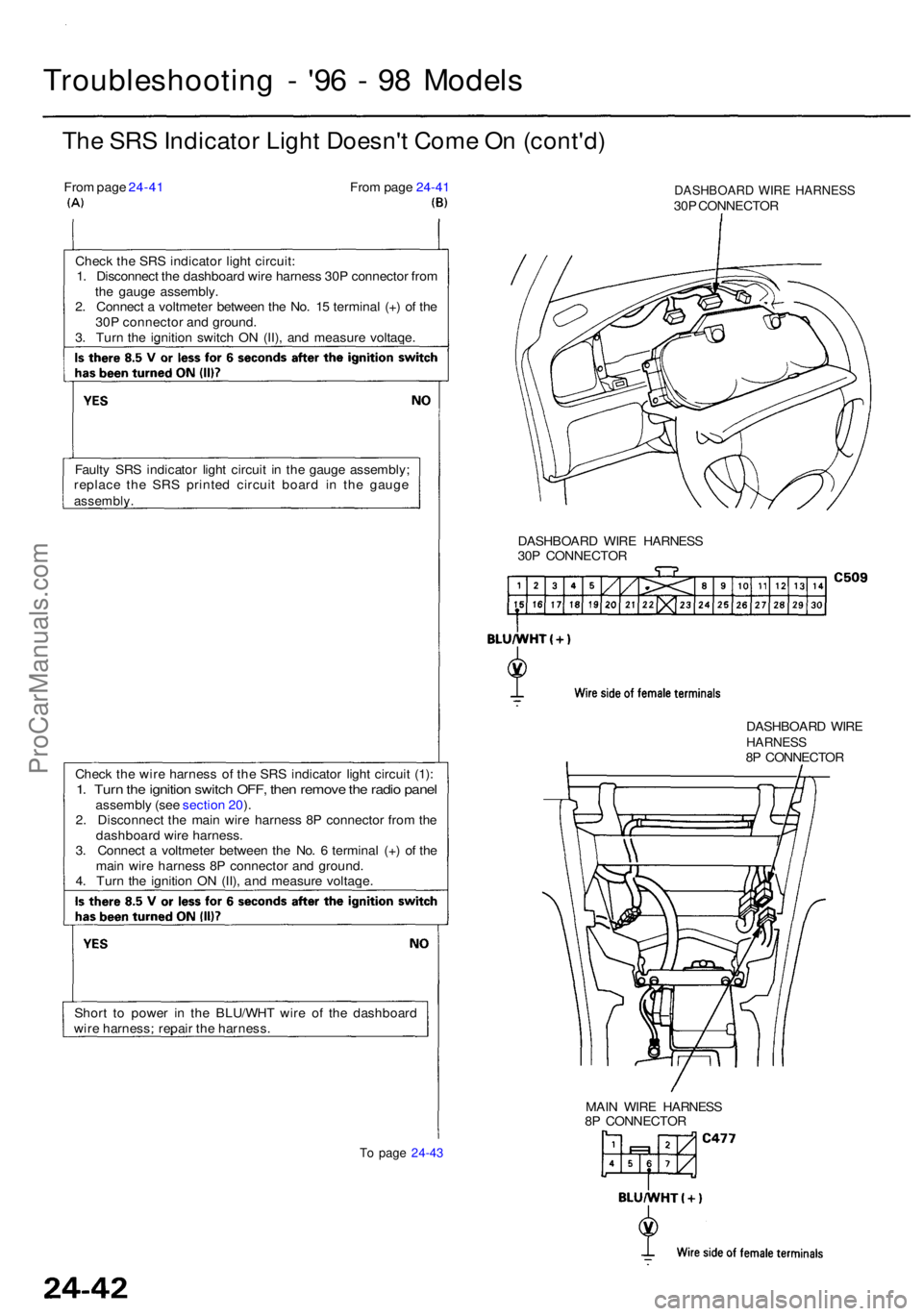
Chec k th e SR S indicato r ligh t circuit :
1 . Disconnec t th e dashboar d wir e harnes s 30 P connecto r fro m
th e gaug e assembly .
2 . Connec t a voltmete r betwee n th e No . 1 5 termina l (+ ) o f th e
30 P connecto r an d ground .
3 . Tur n th e ignitio n switc h O N (II) , an d measur e voltaqe .
Fault y SR S indicato r ligh t circui t i n th e gaug e assembly ;
replac e th e SR S printe d circui t boar d i n th e gaug e
assembly .
Check th e wir e harnes s o f th e SR S indicato r ligh t circui t (1) :1. Tur n th e ignitio n switc h OFF , the n remov e th e radi o pane lassembl y (se e sectio n 20 ).
2 . Disconnec t th e mai n wir e harnes s 8 P connecto r fro m th e
dashboar d wir e harness .
3 . Connec t a voltmete r betwee n th e No . 6 termina l (+ ) o f th e
mai n wir e harnes s 8 P connecto r an d ground .
4 . Tur n th e ignitio n O N (II) , an d measur e voltaqe .
Shor t t o powe r i n th e BLU/WH T wir e o f th e dashboar d
wir e harness : repai r th e harness .
DASHBOAR D WIR E HARNES S30P CONNECTO R
DASHBOAR D WIR E HARNES S
30 P CONNECTO R
DASHBOARD WIR E
HARNES S8P CONNECTO R
MAI N WIR E HARNES S
8 P CONNECTO R
ProCarManuals.com
Page 1864 of 1954
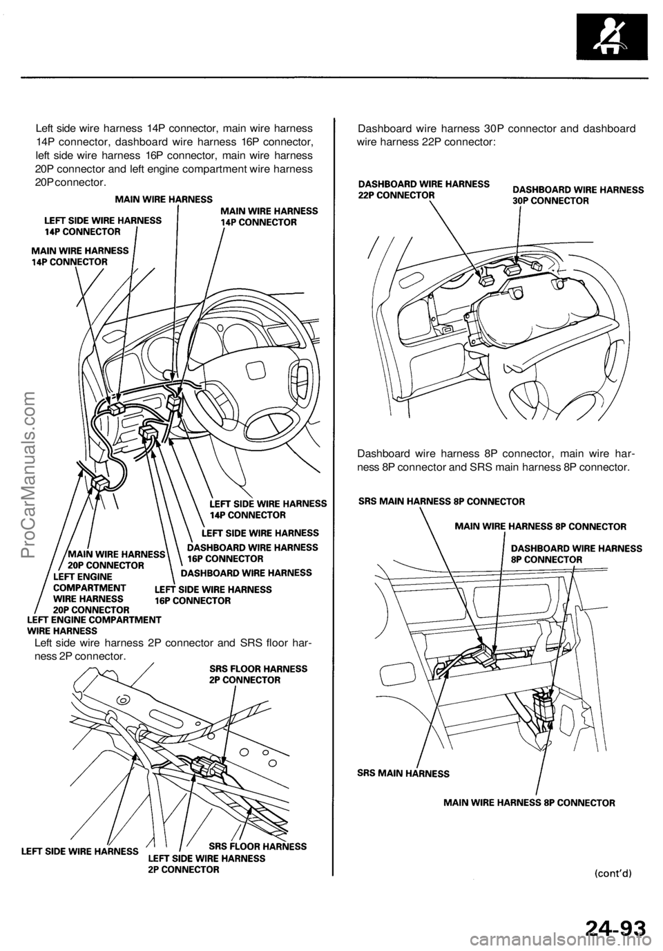
Left side wire harness 14P connector, main wire harness
14P connector, dashboard wire harness 16P connector,
left side wire harness 16P connector, main wire harness
20P connector and left engine compartment wire harness
20P connector.
Dashboard wire harness 30P connector and dashboard
wire harness 22P connector:
Dashboard wire harness 8P connector, main wire har-
ness 8P connector and SRS main harness 8P connector.
Left side wire harness 2P connector and SRS floor har-
ness 2P connector.ProCarManuals.com
Page 1932 of 1954
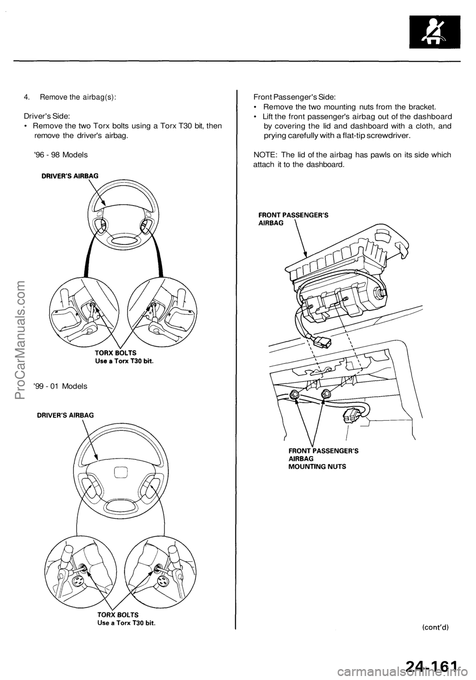
4. Remove the airbag(s):
Driver's Side:
• Remove the two Torx bolts using a Torx T30 bit, then
remove the driver's airbag.
'96 - 98 Models
Front Passenger's Side:
• Remove the two mounting nuts from the bracket.
• Lift the front passenger's airbag out of the dashboard
by covering the lid and dashboard with a cloth, and
prying carefully with a flat-tip screwdriver.
NOTE: The lid of the airbag has pawls on its side which
attach it to the dashboard.
'99 - 01 ModelsProCarManuals.com