dashboard ACURA RL KA9 1996 Service Repair Manual
[x] Cancel search | Manufacturer: ACURA, Model Year: 1996, Model line: RL KA9, Model: ACURA RL KA9 1996Pages: 1954, PDF Size: 61.44 MB
Page 712 of 1954
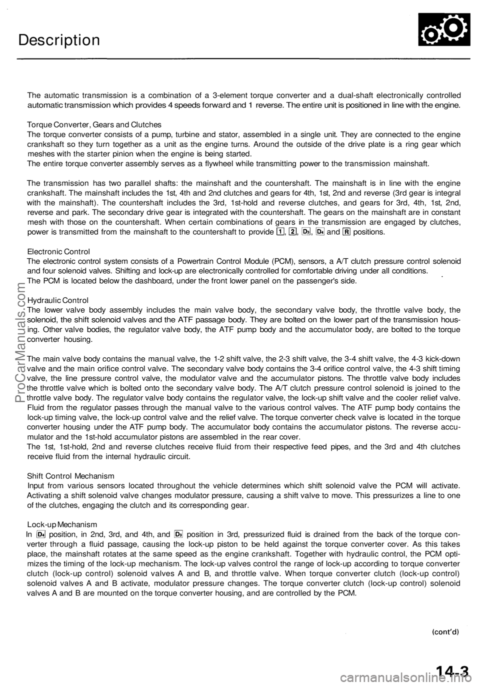
Description
The automatic transmission is a combination of a 3-element torque converter and a dual-shaft electronically controlled
automatic transmission which provides 4 speeds forward and 1 reverse. The entire unit is positioned in line with the engine.
Torque Converter, Gears and Clutches
The torque converter consists of a pump, turbine and stator, assembled in a single unit. They are connected to the engine
crankshaft so they turn together as a unit as the engine turns. Around the outside of the drive plate is a ring gear which
meshes with the starter pinion when the engine is being started.
The entire torque converter assembly serves as a flywheel while transmitting power to the transmission mainshaft.
The transmission has two parallel shafts: the mainshaft and the countershaft. The mainshaft is in line with the engine
crankshaft. The mainshaft includes the 1st, 4th and 2nd clutches and gears for 4th, 1st, 2nd and reverse (3rd gear is integral
with the mainshaft). The countershaft includes the 3rd, 1st-hold and reverse clutches, and gears for 3rd, 4th, 1st, 2nd,
reverse and park. The secondary drive gear is integrated with the countershaft. The gears on the mainshaft are in constant
mesh with those on the countershaft. When certain combinations of gears in the transmission are engaged by clutches,
power is transmitted from the mainshaft to the countershaft to provide , , , and positions.
Electronic Control
The electronic control system consists of a Powertrain Control Module (PCM), sensors, a A/T clutch pressure control solenoid
and four solenoid valves. Shifting and lock-up are electronically controlled for comfortable driving under all conditions.
The PCM is located below the dashboard, under the front lower panel on the passenger's side.
Hydraulic Control
The lower valve body assembly includes the main valve body, the secondary valve body, the throttle valve body, the
solenoid, the shift solenoid valves and the ATF passage body. They are bolted on the lower part of the transmission hous-
ing. Other valve bodies, the regulator valve body, the ATF pump body and the accumulator body, are bolted to the torque
converter housing.
The main valve body contains the manual valve, the 1-2 shift valve, the 2-3 shift valve, the 3-4 shift valve, the 4-3 kick-down
valve and the main orifice control valve. The secondary valve body contains the 3-4 orifice control valve, the 4-3 shift timing
valve, the line pressure control valve, the modulator valve and the accumulator pistons. The throttle valve body includes
the throttle valve which is bolted onto the secondary valve body. The A/T clutch pressure control solenoid is joined to the
throttle valve body. The regulator valve body contains the regulator valve, the lock-up shift valve and the cooler relief valve.
Fluid from the regulator passes through the manual valve to the various control valves. The ATF pump body contains the
lock-up timing valve, the lock-up control valve and the relief valve. The torque converter check valve is located in the torque
converter housing under the ATF pump body. The accumulator body contains the accumulator pistons. The reverse accu-
mulator and the 1st-hold accumulator pistons are assembled in the rear cover.
The 1st, 1st-hold, 2nd and reverse clutches receive fluid from their respective feed pipes, and the 3rd and 4th clutches
receive fluid from the internal hydraulic circuit.
Shift Control Mechanism
Input from various sensors located throughout the vehicle determines which shift solenoid valve the PCM will activate.
Activating a shift solenoid valve changes modulator pressure, causing a shift valve to move. This pressurizes a line to one
of the clutches, engaging the clutch and its corresponding gear.
Lock-up Mechanism
In position, in 2nd, 3rd, and 4th, and position in 3rd, pressurized fluid is drained from the back of the torque con-
verter through a fluid passage, causing the lock-up piston to be held against the torque converter cover. As this takes
place, the mainshaft rotates at the same speed as the engine crankshaft. Together with hydraulic control, the PCM opti-
mizes the timing of the lock-up mechanism. The lock-up valves control the range of lock-up according to torque converter
clutch (lock-up control) solenoid valves A and B, and throttle valve. When torque converter clutch (lock-up control)
solenoid valves A and B activate, modulator pressure changes. The torque converter clutch (lock-up control) solenoid
valves A and B are mounted on the torque converter housing, and are controlled by the PCM.ProCarManuals.com
Page 728 of 1954
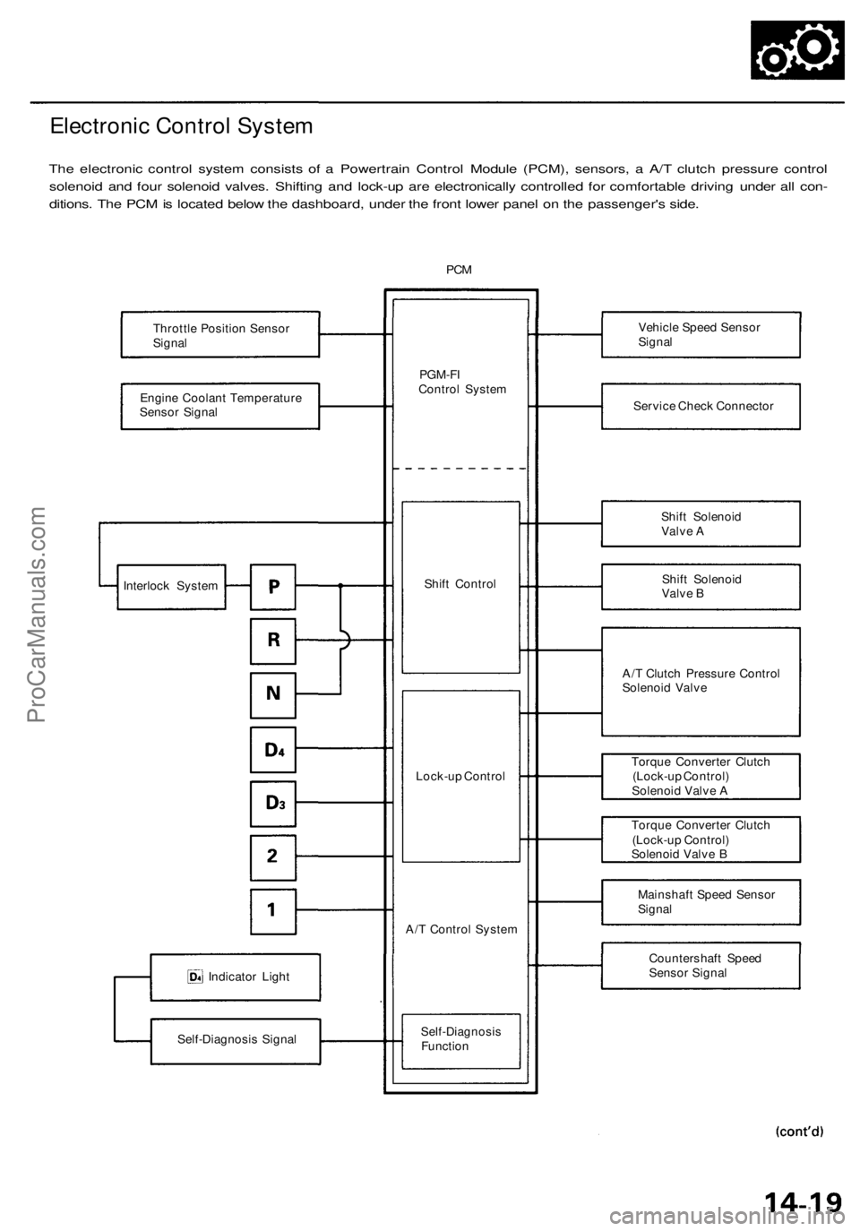
Electronic Control System
The electronic control system consists of a Powertrain Control Module (PCM), sensors, a A/T clutch pressure control
solenoid and four solenoid valves. Shifting and lock-up are electronically controlled for comfortable driving under all con-
ditions. The PCM is located below the dashboard, under the front lower panel on the passenger's side.
PCM
Throttle Position Sensor
Signal
Engine Coolant Temperature
Sensor Signal
Indicator Light
Self-Diagnosis Signal
PGM-FI
Control System
Shift Control
Lock-up Control
A/T Control System
Self-Diagnosis
Function
Vehicle Speed Sensor
Signal
Service Check Connector
Shift Solenoid
Valve A
Shift Solenoid
Valve B
A/T Clutch Pressure Control
Solenoid Valve
Torque Converter Clutch
(Lock-up Control)
Solenoid Valve A
Torque Converter Clutch
(Lock-up Control)
Solenoid Valve B
Mainshaft Speed Sensor
Signal
Countershaft Speed
Sensor Signal
Interlock SystemProCarManuals.com
Page 1334 of 1954
Windshield
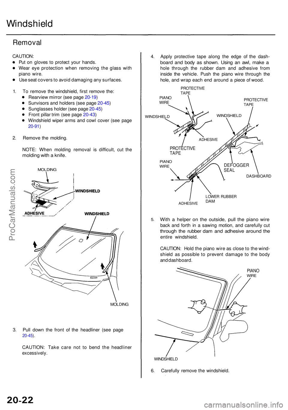
Removal
CAUTION :
Pu t o n glove s t o protec t you r hands .
Wea r ey e protectio n whe n removin g th e glas s wit h
pian o wire .
Us e sea t cover s to avoi d damagin g an y surfaces .
1 . T o remov e th e windshield , firs t remov e the :
Rearvie w mirro r (se e pag e 20-19 )
Sunvisor s an d holder s (se e pag e 20-45 )
Sunglasse s holde r (se e pag e 20-45 )
Fron t pilla r tri m (se e pag e 20-43 )
Windshiel d wipe r arm s an d cow l cove r (se e pag e
20-91 )
2. Remov e th e molding .
NOTE : Whe n moldin g remova l i s difficult , cu t th e
moldin g wit h a knife .
MOLDIN G
MOLDIN G
3. Pul l dow n th e fron t o f th e headline r (se e pag e
20-45 ).
CAUTION : Tak e car e no t t o ben d th e headline r
excessively .
4. Appl y protectiv e tap e alon g th e edg e o f th e dash -
board an d bod y a s shown . Usin g a n awl , mak e a
hol e throug h th e rubbe r da m an d adhesiv e fro m
insid e th e vehicle . Pus h th e pian o wir e throug h th e
hole , an d wra p eac h en d aroun d a piec e o f wood .
PROTECTIV ETAPEPIAN OWIRE
WINDSHIEL D
PROTECTIV ETAPE
PIAN OWIRE
DASHBOAR D
ADHESIVE
LOWER RUBBE RDAM
5.Wit h a helpe r o n th e outside , pul l th e pian o wir e
back an d fort h i n a sawin g motion , an d carefull y cu t
throug h th e rubbe r da m an d adhesiv e aroun d th e
entir e windshield .
CAUTION : Hol d th e pian o wir e a s clos e t o th e wind -
shiel d a s possibl e t o preven t damag e t o th e bod y
an d dashboard .
PIANOWIRE
WINDSHIEL D
6. Carefull y remov e th e windshield .
WINDSHIEL D
ADHESIVE
PROTECTIVETAPE
DEFOGGE RSEAL
ProCarManuals.com
Page 1349 of 1954
Moonroof
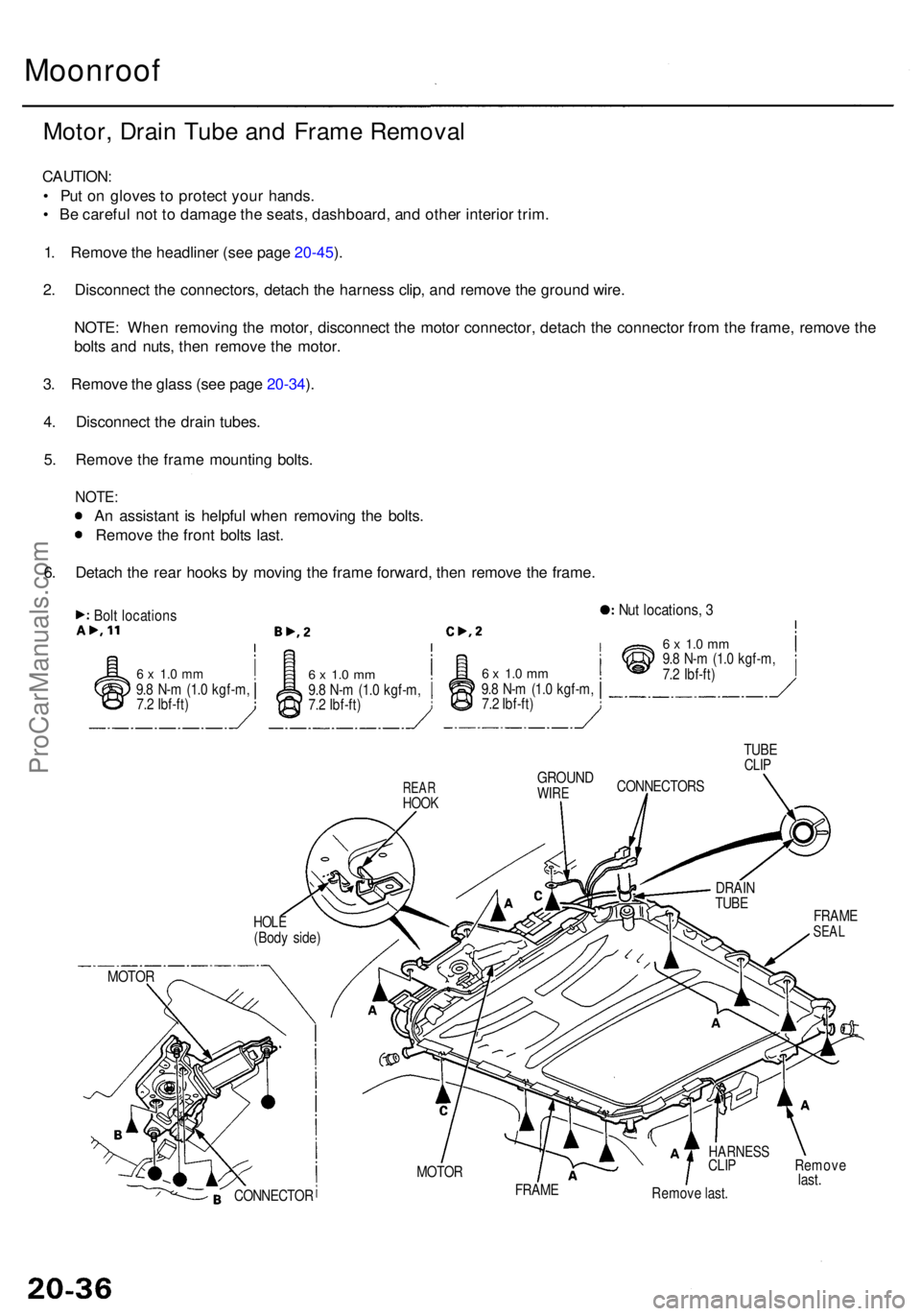
Motor, Drai n Tub e an d Fram e Remova l
CAUTION :
• Pu t o n glove s to protec t you r hands .
• B e carefu l no t t o damag e th e seats , dashboard , an d othe r interio r trim .
1 . Remov e th e headline r (se e pag e 20-45 ).
2 . Disconnec t th e connectors , detac h th e harnes s clip , an d remov e th e groun d wire .
NOTE : Whe n removin g th e motor , disconnec t th e moto r connector , detac h th e connecto r fro m th e frame , remov e th e
bolt s an d nuts , the n remov e th e motor .
3 . Remov e th e glas s (se e pag e 20-34 ).
4 . Disconnec t th e drai n tubes .
5 . Remov e th e fram e mountin g bolts .
NOTE :
An assistan t i s helpfu l whe n removin g th e bolts .
Remov e th e fron t bolt s last .
6 . Detac h th e rea r hook s b y movin g th e fram e forward , the n remov e th e frame .
Bolt location sNut locations , 3
6 x 1. 0 m m9.8 N- m (1. 0 kgf-m ,
7. 2 Ibf-ft )6 x 1. 0 m m9.8 N- m (1. 0 kgf-m ,
7. 2 Ibf-ft )6 x 1. 0 m m9.8 N- m (1. 0 kgf-m ,
7. 2 Ibf-ft )
6 x 1. 0 m m9.8 N- m (1. 0 kgf-m ,
7. 2 Ibf-ft )
REARHOO K
GROUN DWIRE
MOTO R
CONNECTO R
HARNESSCLIP Remov elast.Remov e last .
HOL E(Bod y side )
MOTOR TUB
E
CLIP
CONNECTOR S
FRAME
SEAL
DRAI N
TUB E
FRAM E
ProCarManuals.com
Page 1365 of 1954
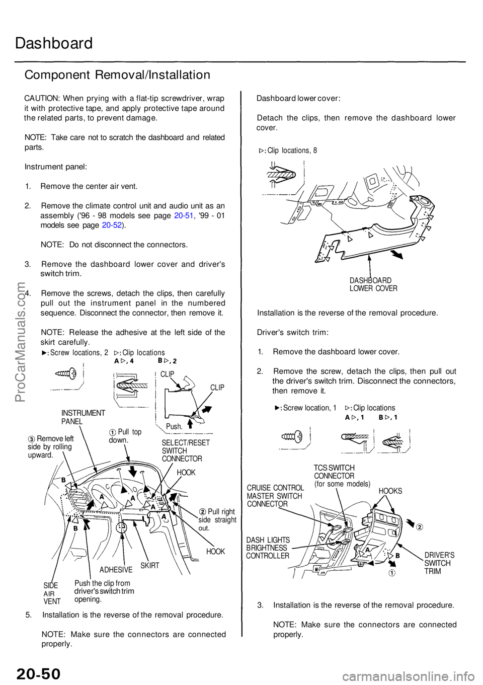
Dashboard
Componen t Removal/Installatio n
CAUTION: Whe n pryin g wit h a flat-ti p screwdriver , wra p
i t wit h protectiv e tape , an d appl y protectiv e tap e aroun d
th e relate d parts , t o preven t damage .
NOTE : Tak e car e no t t o scratc h th e dashboar d an d relate d
parts .
Instrumen t panel :
1. Remov e th e cente r ai r vent .
2 . Remov e th e climat e contro l uni t an d audi o uni t a s a n
assembl y ('9 6 - 9 8 model s se e pag e 20-51 , '9 9 - 0 1
model s se e pag e 20-52 ).
NOTE : D o no t disconnec t th e connectors .
3 . Remov e th e dashboar d lowe r cove r an d driver' s
switch trim .
4. Remov e th e screws , detac h th e clips , the n carefull y
pul l ou t th e instrumen t pane l i n th e numbere d
sequence . Disconnec t th e connector , the n remov e it .
NOTE : Releas e th e adhesiv e a t th e lef t sid e o f th e
skir t carefully .
CLIP
INSTRUMEN TPANEL
Remov e lef tsid e b y rollin gupward .
Pull to pdown .SELECT/RESE T
SWITC H
CONNECTO R
HOO K
Pull righ tside straigh tout.
HOO K
SID E
AIRVEN T
Push th e cli p fro mdriver' s switc h tri mopening .
5. Installatio n i s th e revers e o f th e remova l procedure .
NOTE : Mak e sur e th e connector s ar e connecte d
properly . Dashboar
d lowe r cover :
Detac h th e clips , the n remov e th e dashboar d lowe r
cover.
DASHBOAR D
LOWE R COVE R
Installatio n is th e revers e o f th e remova l procedure .
Driver' s switc h trim :
1 . Remov e th e dashboar d lowe r cover .
2 . Remov e th e screw , detac h th e clips , the n pul l ou t
the driver' s switc h trim . Disconnec t th e connectors ,
then remov e it .
CRUIS E CONTRO L
MASTE R SWITC H
CONNECTO R
DAS H LIGHT S
BRIGHTNES S
CONTROLLE R
TCS SWITC HCONNECTO R
(fo r som e models )
HOOK S
DRIVER' SSWITCHTRIM
3. Installatio n i s th e revers e o f th e remova l procedure .
NOTE : Mak e sur e th e connector s ar e connecte d
properly .
Screw locations , 2 Clip location s
CLIP
Push .
SKIR TADHESIV E
Clip location s
Scre w location , 1
Cli p locations , 8
ProCarManuals.com
Page 1367 of 1954
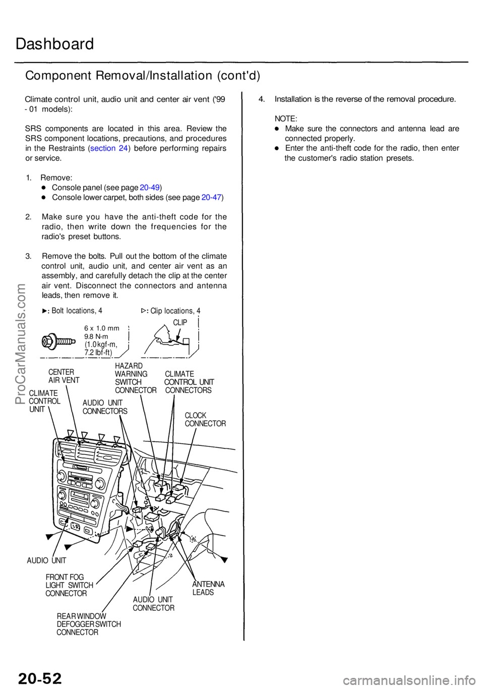
Dashboard
Componen t Removal/Installatio n (cont'd )
Climate contro l unit , audi o uni t an d cente r ai r ven t ('9 9
- 0 1 models) :
SR S component s ar e locate d i n thi s area . Revie w th e
SR S componen t locations , precautions , an d procedure s
i n th e Restraint s ( sectio n 24 ) befor e performin g repair s
o r service .
1 . Remove :
Consol e pane l (se e pag e 20-49 )
Consol e lowe r carpet , bot h side s (se e pag e 20-47 )
2.
3.
Mak e sur e yo u hav e th e anti-thef t cod e fo r th e
radio , the n writ e dow n th e frequencie s fo r th e
radio' s prese t buttons .
Remov e th e bolts . Pul l ou t th e botto m o f th e climat e
contro l unit , audi o unit , an d cente r ai r ven t a s a n
assembly , an d carefull y detac h th e cli p a t th e cente r
ai r vent . Disconnec t th e connector s an d antenn a
leads , the n remov e it .
Bol t locations , 4
6 x 1. 0 m m9.8 N- m(1.0 kgf-m ,
7. 2 Ibf-ft ) Cli
p locations , 4
CLI P
CENTE RAIR VEN T
CLIMAT ECONTRO LUNIT
HAZAR DWARNIN G CLIMAT ESWITCH CONTRO L UNI TCONNECTO R CONNECTOR S
CLOCKCONNECTO R
AUDIO UNI T
FRON T FO G
LIGH T SWITC H
CONNECTO R
REA R WINDO W
DEFOGGE R SWITC H
CONNECTO R
ANTENNALEADSAUDIO UNI TCONNECTO R
4. Installatio n is th e revers e o f th e remova l procedure .
NOTE:
Make sur e th e connector s an d antenn a lea d ar e
connecte d properly .
Ente r th e anti-thef t cod e fo r th e radio , the n ente r
th e customer' s radi o statio n presets .
AUDIO UNI T
CONNECTOR S
ProCarManuals.com
Page 1368 of 1954
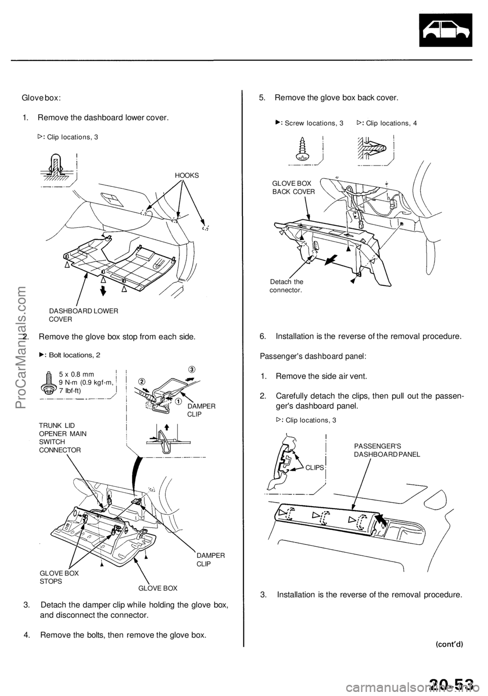
Glove box :
1 . Remov e th e dashboar d lowe r cover .
HOOK S
DASHBOAR D LOWE R
COVER
2. Remov e th e glov e bo x sto p fro m eac h side .
Bolt locations , 2
5 x 0. 8 m m9 N- m (0. 9 kgf-m ,7 Ibf-ft )
TRUN K LI D
OPENE R MAI N
SWITC H
CONNECTO R
DAMPERCLIP
DAMPE RCLIP
GLOV E BO X
STOP S
GLOVE BO X
3. Detac h th e dampe r cli p whil e holdin g th e glov e box ,
an d disconnec t th e connector .
4 . Remov e th e bolts , the n remov e th e glov e box . 5
. Remov e th e glov e bo x bac k cover .
Clip locations , 4
GLOV E BO X
BAC K COVE R
6. Installatio n is th e revers e o f th e remova l procedure .
Passenger' s dashboar d panel :
1. Remov e th e sid e ai r vent .
2 . Carefull y detac h th e clips , the n pul l ou t th e passen -
ger' s dashboar d panel .
PASSENGER' SDASHBOARD PANE L
3. Installatio n i s th e revers e o f th e remova l procedure .
CLIPS
Clip locations , 3
Detac
h th e
connector .
Scre
w locations , 3
Cli p locations , 3
ProCarManuals.com
Page 1370 of 1954
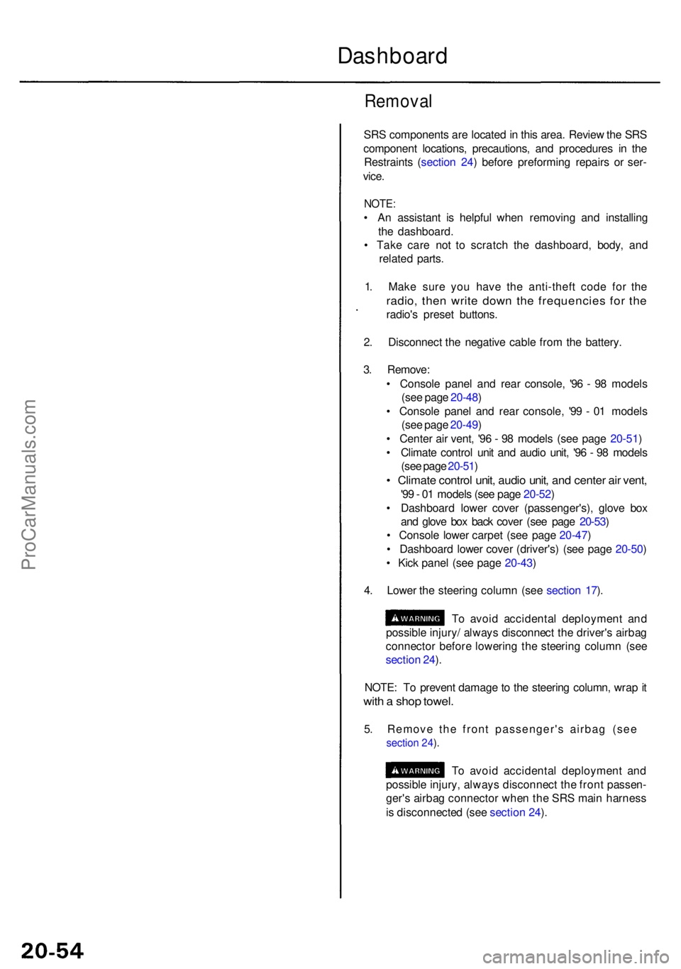
Removal
SRS component s ar e locate d in thi s area . Revie w th e SR S
componen t locations , precautions , an d procedure s i n th e
Restraint s ( sectio n 24 ) befor e preformin g repair s o r ser -
vice .
NOTE :
• A n assistan t i s helpfu l whe n removin g an d installin g
th e dashboard .
• Tak e car e no t t o scratc h th e dashboard , body , an d
relate d parts .
1 . Mak e sur e yo u hav e th e anti-thef t cod e fo r th e
radio , the n writ e dow n th e frequencie s fo r th e
radio' s prese t buttons .
2 . Disconnec t th e negativ e cabl e fro m th e battery .
3 . Remove :
• Consol e pane l an d rea r console , '9 6 - 9 8 model s
(se e pag e 20-48 )
• Consol e pane l an d rea r console , '9 9 - 0 1 model s
(se e pag e 20-49 )
• Cente r ai r vent , '9 6 - 9 8 model s (se e pag e 20-51 )
• Climat e contro l uni t an d audi o unit , '9 6 - 9 8 model s
(se e pag e 20-51 )
• Climat e contro l unit , audi o unit , an d cente r ai r vent ,
'99 - 0 1 model s (se e pag e 20-52 )
• Dashboar d lowe r cove r (passenger's) , glov e bo x
an d glov e bo x bac k cove r (se e pag e 20-53 )
• Consol e lowe r carpe t (se e pag e 20-47 )
• Dashboar d lowe r cove r (driver's ) (se e pag e 20-50 )
• Kic k pane l (se e pag e 20-43 )
4 . Lowe r th e steerin g colum n (se e sectio n 17 ).
T o avoi d accidenta l deploymen t an d
possibl e injury / alway s disconnec t th e driver' s airba g
connecto r befor e lowerin g th e steerin g colum n (se e
sectio n 24 ).
NOTE : T o preven t damag e to th e steerin g column , wra p it
wit h a sho p towel .
5. Remove the front passenger's airbag (see
section 24 ).
T o avoi d accidenta l deploymen t an d
possibl e injury , alway s disconnec t th e fron t passen -
ger' s airba g connecto r whe n th e SR S mai n harnes s
i s disconnecte d (se e sectio n 24 ).
Dashboar d
ProCarManuals.com
Page 1371 of 1954
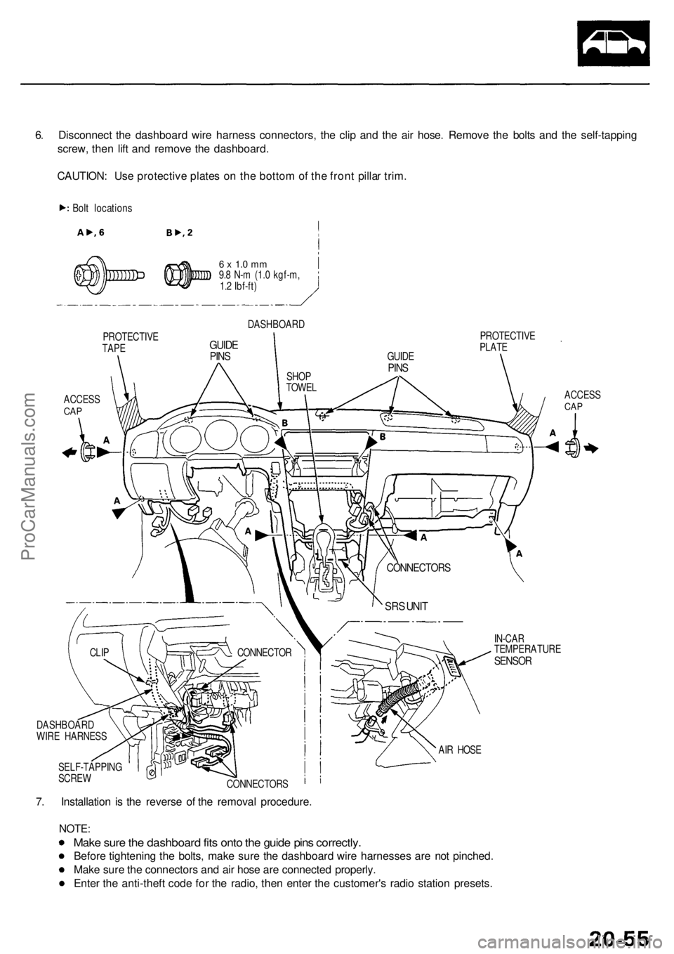
6. Disconnec t th e dashboar d wir e harnes s connectors , th e cli p an d th e ai r hose . Remov e th e bolt s an d th e self-tappin g
screw , the n lif t an d remov e th e dashboard .
CAUTION : Us e protectiv e plate s o n th e botto m of th e fron t pilla r trim .
Bolt location s
PROTECTIV E
TAPE
ACCES SCAP
6 x 1. 0 m m9.8 N- m (1. 0 kgf-m ,
1. 2 Ibf-ft )
DASHBOAR D
GUIDEPINS
PROTECTIV E
PLAT E
ACCESS
CAP
IN-CA R
TEMPERATUR E
SENSOR
7. Installatio n i s th e revers e o f th e remova l procedure .
NOTE:
Make sur e th e dashboar d fit s ont o th e guid e pin s correctly .
Before tightenin g th e bolts , mak e sur e th e dashboar d wir e harnesse s ar e no t pinched .
Mak e sur e th e connector s an d ai r hos e ar e connecte d properly .
Ente r th e anti-thef t cod e fo r th e radio , the n ente r th e customer' s radi o statio n presets .
SELF-TAPPIN G
SCRE W
CONNECTORS AI
R HOS E
CONNECTO
R
CLIP
DASHBOAR D
WIR E HARNES S
SRS UNI T
CONNECTOR S
GUIDEPINSSHO P
TOWE L
ProCarManuals.com
Page 1410 of 1954
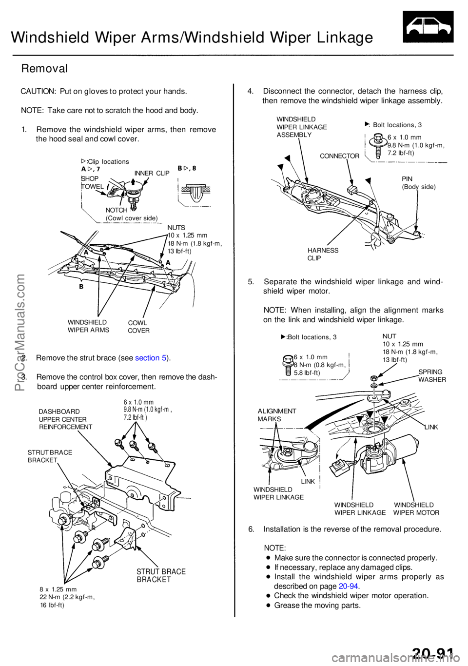
Windshield Wipe r Arms/Windshiel d Wipe r Linkag e
Remova l
CAUTION : Pu t o n glove s to protec t you r hands .
NOTE : Tak e car e no t t o scratc h th e hoo d an d body .
1 . Remov e th e windshiel d wipe r arms , the n remov e
th e hoo d sea l an d cow l cover .
INNER CLI P
NOTC H
(Cow l cove r side )
NUTS10 x 1.2 5 mm18 N- m (1. 8 kgf-m ,
1 3 Ibf-ft )
WINDSHIEL D
WIPE R ARM S COW
L
COVE R
2. Remov e th e stru t brac e (se e sectio n 5 ).
3 . Remov e th e contro l bo x cover , the n remov e th e dash -
boar d uppe r cente r reinforcement .
DASHBOARD
UPPE R CENTE R
REINFORCEMEN T
STRU T BRAC E
BRACKE T
6 x 1.0 mm9.8 N-m (1.0 kgf-m ,7.2 Ibf-ft )
STRUT BRACEBRACKE T
8 x 1.2 5 mm22 N- m (2. 2 kgf-m ,16 Ibf-ft )
4. Disconnec t th e connector , detac h th e harnes s clip ,
the n remov e th e windshiel d wipe r linkag e assembly .
WINDSHIEL D
WIPE R LINKAG E
ASSEMBL Y
: Bol t locations , 3
6 x 1. 0 m m9.8 N- m (1. 0 kgf-m ,
7. 2 Ibf-ft )
PIN(Bod y side )
HARNES S
CLIP
5. Separat e th e windshiel d wipe r linkag e an d wind -
shiel d wipe r motor .
NOTE : Whe n installing , alig n th e alignmen t mark s
o n th e lin k an d windshiel d wipe r linkage .
6 x 1. 0 m m8 N- m (0. 8 kgf-m ,
5. 8 Ibf-ft )
ALIGNMEN TMARKSLINK
LIN KWINDSHIEL D
WIPE R LINKAG E
WINDSHIELD WINDSHIEL D
WIPE R LINKAG E WIPE R MOTO R
6. Installatio n is th e revers e o f th e remova l procedure .
NOTE:
Make sur e th e connecto r i s connecte d properly .
I f necessary , replac e an y damage d clips .
Instal l th e windshiel d wipe r arm s properl y a s
describe d o n pag e 20-94 .
Chec k th e windshiel d wipe r moto r operation .
Greas e th e movin g parts .
SHOP
TOWE L
Cli
p location s CONNECTO
R
Bol t locations , 3
NU T10 x 1.2 5 mm18 N- m (1. 8 kgf-m ,
1 3 Ibf-ft )
SPRIN G
WASHE R
ProCarManuals.com