navigation ACURA RL KA9 1996 Service Owner's Manual
[x] Cancel search | Manufacturer: ACURA, Model Year: 1996, Model line: RL KA9, Model: ACURA RL KA9 1996Pages: 1954, PDF Size: 61.44 MB
Page 253 of 1954
Navigation Syste m
Sympto m Troubleshootin g (cont'd )
4. Tur n th e ignitio n switc h OFF .
5 . Substitut e a known-goo d displa y unit , an d recheck .
Is the picture OK?
YES—Replac e th e displa y uni t (se e pag e 23-54 ).
NO—Replac e th e navigatio n uni t
(se e pag e 23-53 ).
ProCarManuals.com
Page 254 of 1954
Navigation Syste m
Sympto m Troubleshootin g (cont'd )
Display uni t button s d o no t wor k
NOTE :
• Alway s chec k th e connector s fo r poo r connection s o r
loos e terminals .
• Befor e troubleshooting , ge t th e navigatio n syste m
anti-thef t codes .
• Afte r troubleshooting , ente r th e navigatio n syste m
anti-thef t codes .
1. Tur n th e ignitio n switc h to AC C (I) .
2. G o int o th e Diagnosti c mod e an d us e "Touc h Panel "
diagnosti c unde r Monito r Chec k (se e pag e 23-41 )
and, i f necessary , "Display " diagnosti c unde r Uni t
Chec k (se e pag e 23-43 ).
Do the buttons work properly?
YES—System is OK .
NO—G o t o ste p 3 .
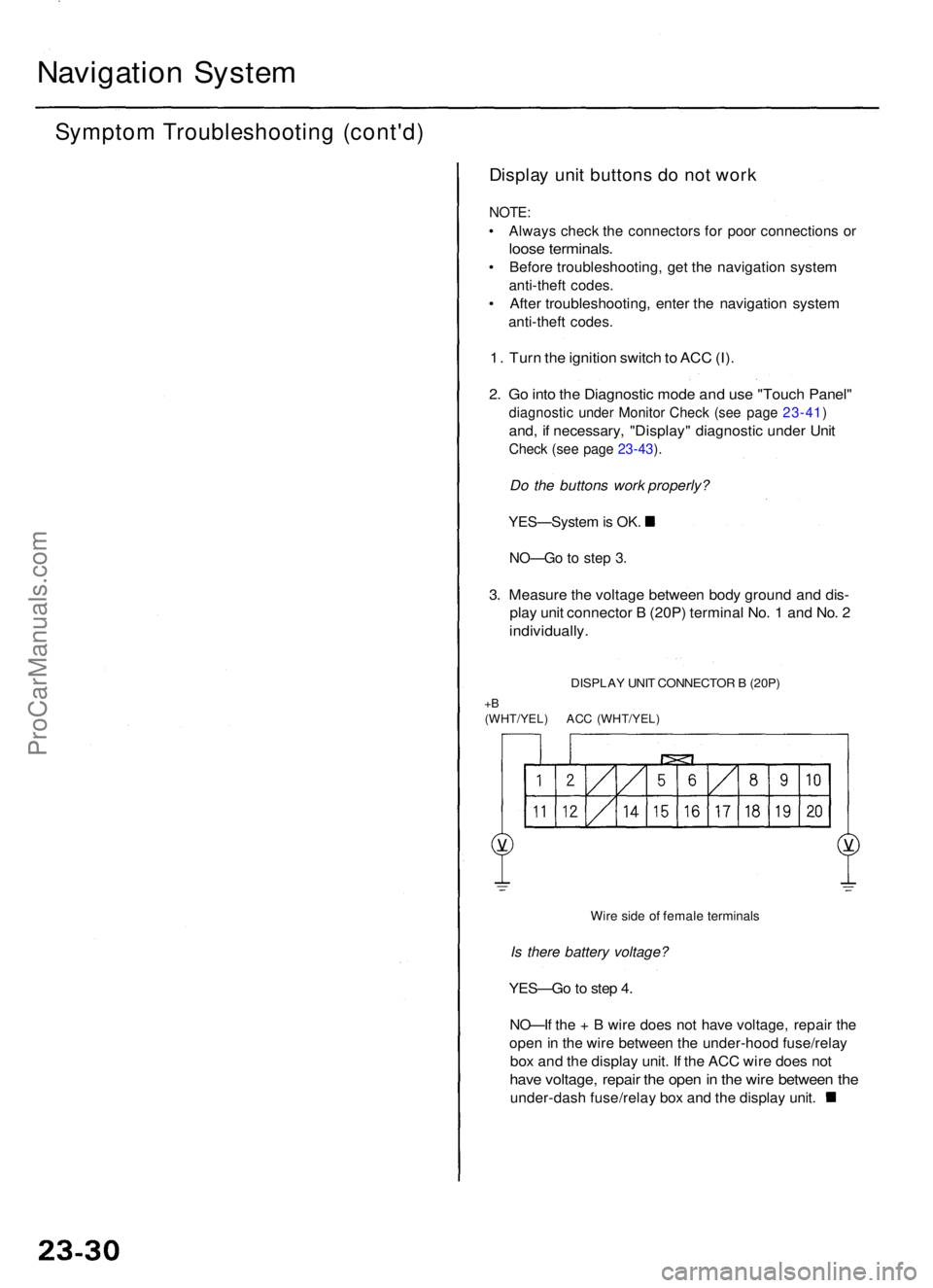
3. Measur e th e voltag e betwee n bod y groun d an d dis -
play uni t connecto r B (20P ) termina l No . 1 an d No . 2
individually .
DISPLAY UNI T CONNECTO R B (20P )
+B(WHT/YEL ) AC C (WHT/YEL )
Wire sid e o f femal e terminal s
Is there battery voltage?
YES—G o to ste p 4 .
NO—I f th e + B wir e doe s no t hav e voltage , repai r th e
ope n in th e wir e betwee n th e under-hoo d fuse/rela y
box an d th e displa y unit . I f th e AC C wir e doe s no t
hav e voltage , repai r th e ope n in th e wir e betwee n th e
under-das h fuse/rela y bo x an d th e displa y unit .
ProCarManuals.com
Page 255 of 1954
- +
BODY
4. Turn the ignition switch OFF.
5. Disconnect the display unit connector B (20P).
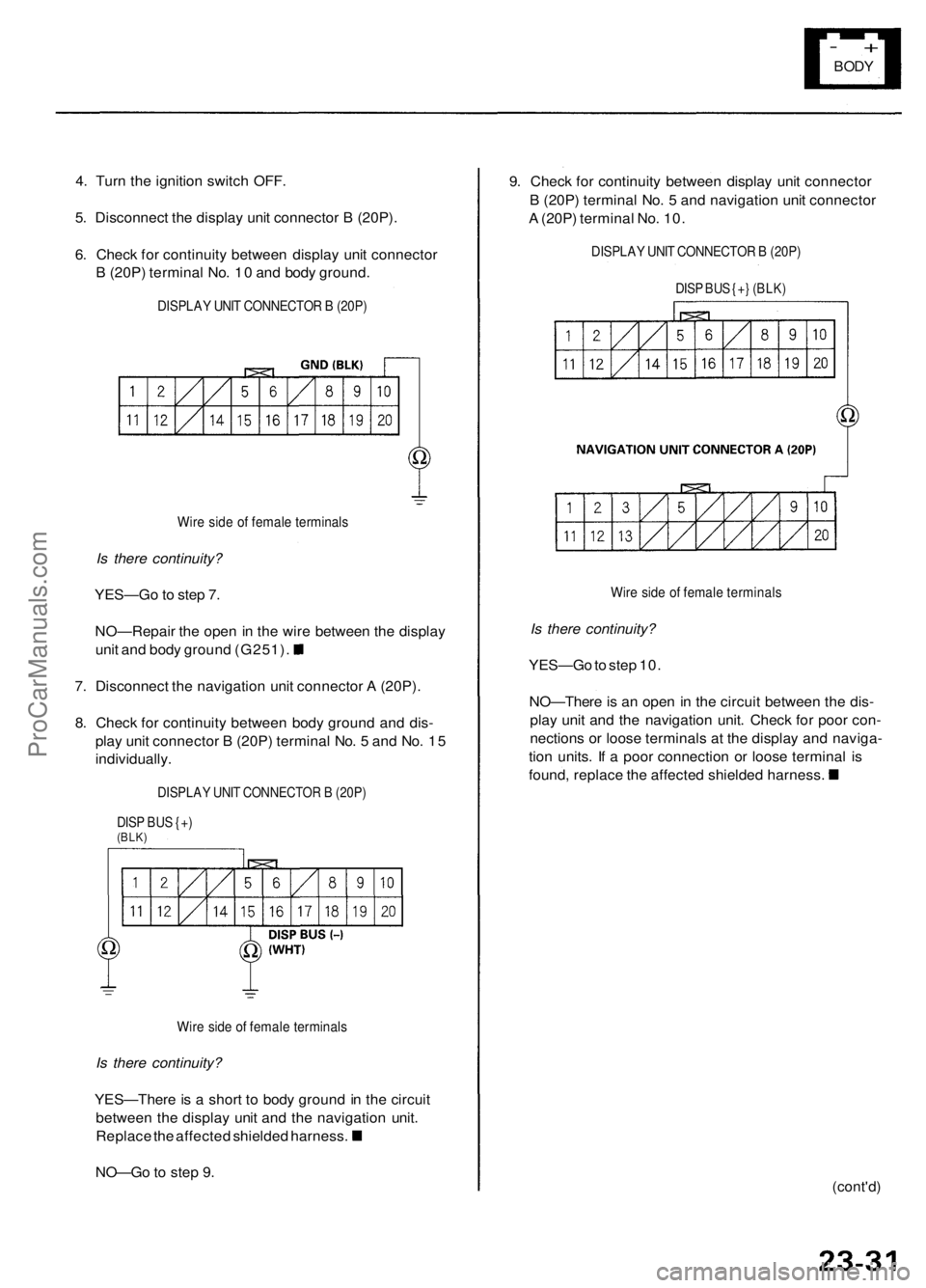
6. Check for continuity between display unit connector
B (20P) terminal No. 10 and body ground.
DISPLAY UNIT CONNECTOR B (20P)
Wire side of female terminals
Is there continuity?
YES—Go to step 7.
NO—Repair the open in the wire between the display
unit and body ground (G251).
7. Disconnect the navigation unit connector A (20P).
8. Check for continuity between body ground and dis-
play unit connector B (20P) terminal No. 5 and No. 15
individually.
DISPLAY UNIT CONNECTOR B (20P)
DISP BUS {+)
(BLK)
Wire side of female terminals
Is there continuity?
YES—There is a short to body ground in the circuit
between the display unit and the navigation unit.
Replace the affected shielded harness.
NO—Go to step 9.
9. Check for continuity between display unit connector
B (20P) terminal No. 5 and navigation unit connector
A (20P) terminal No. 10.
DISPLAY UNIT CONNECTOR B (20P)
DISP BUS {+} (BLK)
Wire side of female terminals
Is there continuity?
YES—Go to step 10.
NO—There is an open in the circuit between the dis-
play unit and the navigation unit. Check for poor con-
nections or loose terminals at the display and naviga-
tion units. If a poor connection or loose terminal is
found, replace the affected shielded harness.
(cont'd)ProCarManuals.com
Page 256 of 1954
Navigation Syste m
Sympto m Troubleshootin g (cont'd )
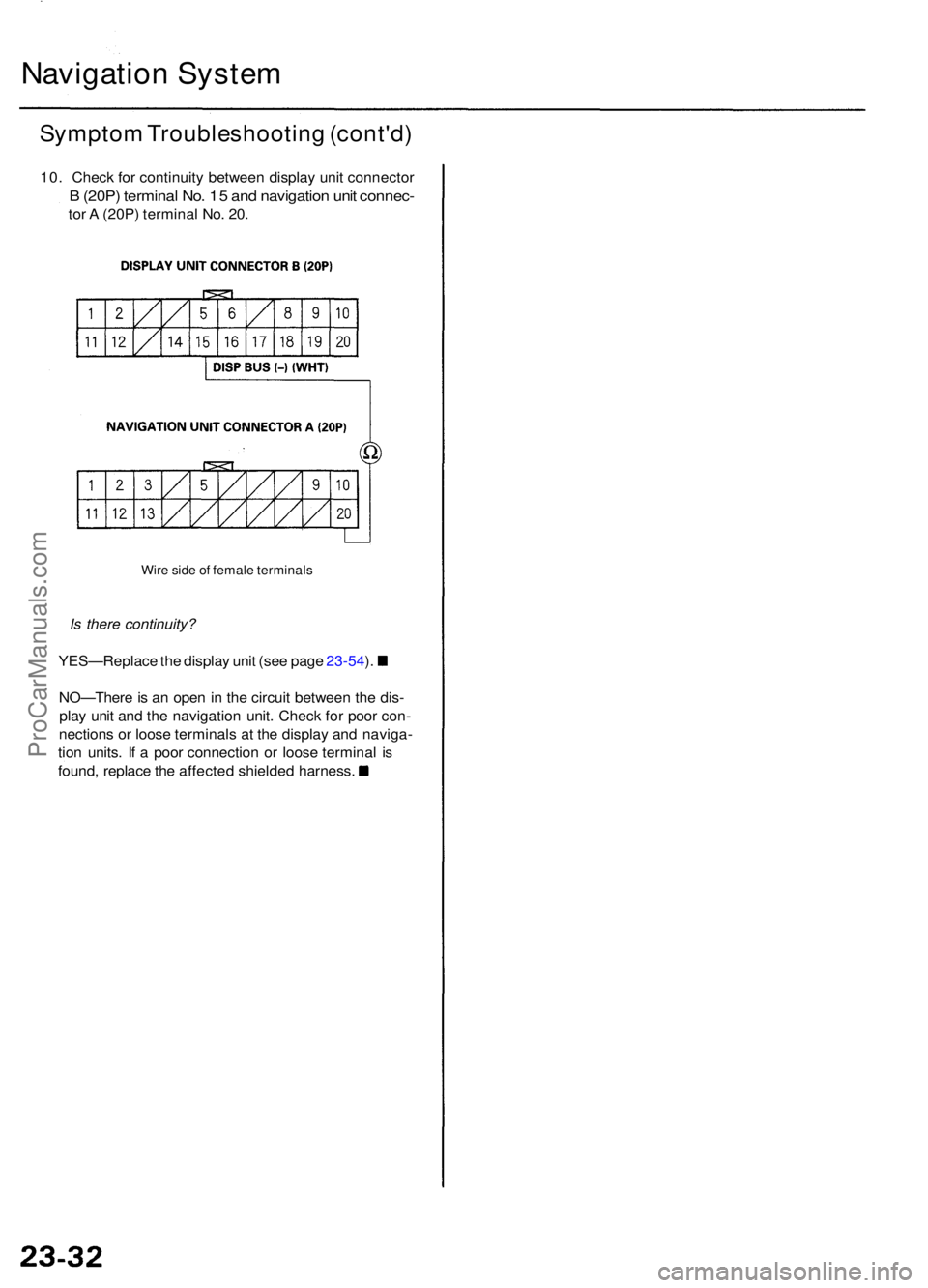
10. Chec k fo r continuit y betwee n displa y uni t connecto r
B (20P ) termina l No . 1 5 an d navigatio n uni t connec -
tor A (20P ) termina l No . 20 .
Wir e sid e o f femal e terminal s
Is there continuity?
YES—Replac e th e displa y uni t (se e pag e 23-54 ).
NO—Ther e is a n ope n in th e circui t betwee n th e dis -
pla y uni t an d th e navigatio n unit . Chec k fo r poo r con -
nection s o r loos e terminal s a t th e displa y an d naviga -
tio n units . I f a poo r connectio n o r loos e termina l i s
found , replac e th e affecte d shielde d harness .
ProCarManuals.com
Page 257 of 1954
Navigation Syste m
Sympto m Troubleshootin g (cont'd )
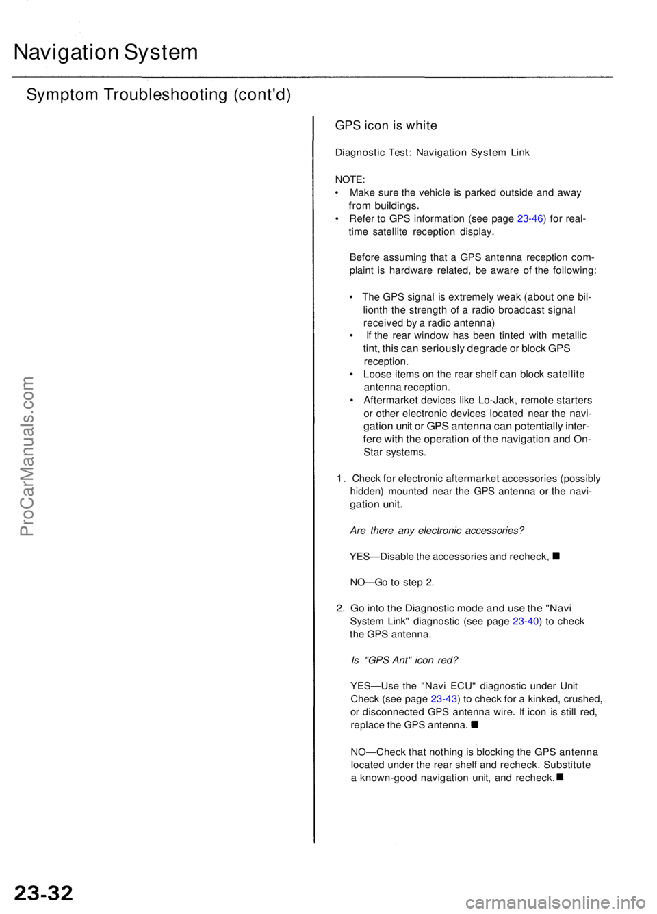
GPS ico n is whit e
Diagnosti c Test : Navigatio n Syste m Lin k
NOTE :
• Mak e sur e th e vehicl e i s parke d outsid e an d awa y
from buildings .
• Refe r t o GP S informatio n (se e pag e 23-46 ) fo r real -
tim e satellit e receptio n display .
Befor e assumin g tha t a GP S antenn a receptio n com -
plain t i s hardwar e related , b e awar e o f th e following :
• Th e GP S signa l i s extremel y wea k (abou t on e bil -
liont h th e strengt h o f a radi o broadcas t signa l
receive d b y a radi o antenna )
• I f th e rea r windo w ha s bee n tinte d wit h metalli c
tint, thi s ca n seriousl y degrad e o r bloc k GP S
reception .
• Loos e item s o n th e rea r shel f ca n bloc k satellit e
antenn a reception .
• Aftermarke t device s lik e Lo-Jack , remot e starter s
o r othe r electroni c device s locate d nea r th e navi -
gation uni t o r GP S antenn a ca n potentiall y inter -
fere wit h th e operatio n o f th e navigatio n an d On -
Star systems .
1 . Chec k fo r electroni c aftermarke t accessorie s (possibl y
hidden ) mounte d nea r th e GP S antenn a o r th e navi -
gation unit .
Are there any electronic accessories?
YES—Disabl e th e accessorie s an d recheck ,
NO—G o t o ste p 2 .
2. G o int o th e Diagnosti c mod e an d us e th e "Nav i
Syste m Link " diagnosti c (se e pag e 23-40 ) t o chec k
th e GP S antenna .
Is "GPS Ant" icon red?
YES—Us e th e "Nav i ECU " diagnosti c unde r Uni t
Chec k (se e pag e 23-43 ) t o chec k fo r a kinked , crushed ,
o r disconnecte d GP S antenn a wire . I f ico n i s stil l red ,
replac e th e GP S antenna .
NO—Chec k tha t nothin g is blockin g th e GP S antenn a
locate d unde r th e rea r shel f an d recheck . Substitut e
a known-goo d navigatio n unit , an d recheck .
ProCarManuals.com
Page 259 of 1954
Navigation Syste m
Sympto m Troubleshootin g (cont'd )
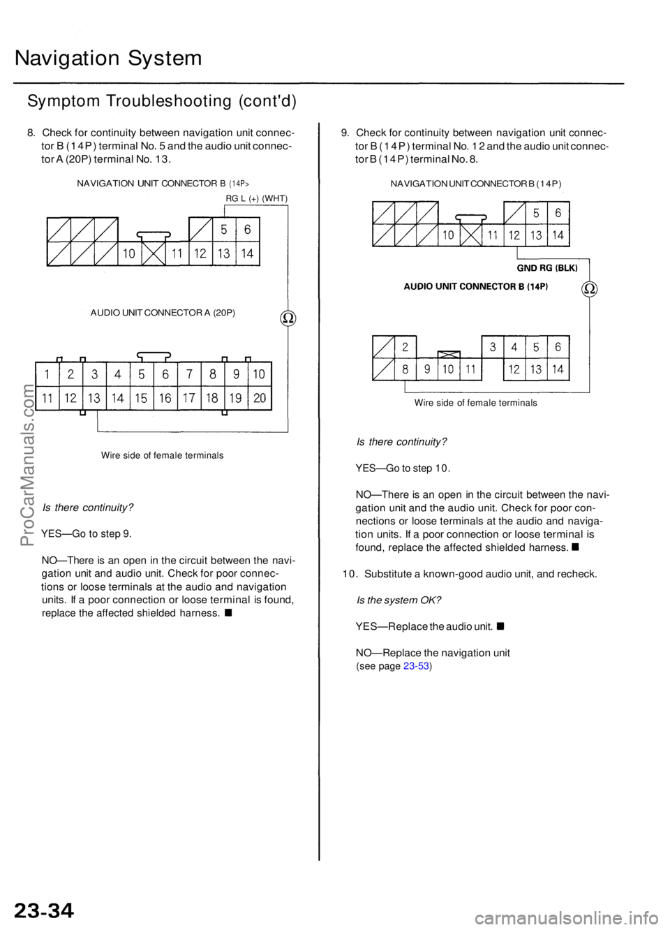
8. Chec k fo r continuit y betwee n navigatio n uni t connec -
tor B (14P ) termina l No . 5 an d th e audi o uni t connec -
tor A (20P ) termina l No . 13 .
NAVIGATIO N UNIT CONNECTO R B (14P>
RG L (+ ) (WHT )
AUDIO UNI T CONNECTO R A (20P )
Wire sid e o f femal e terminal s
Is there continuity?
YES—G o to ste p 9 .
NO—Ther e is a n ope n i n th e circui t betwee n th e navi -
gatio n uni t an d audi o unit . Chec k fo r poo r connec -
tions o r loos e terminal s a t th e audi o an d navigatio n
units. I f a poo r connectio n o r loos e termina l i s found ,
replace th e affecte d shielde d harness .
9. Chec k fo r continuit y betwee n navigatio n uni t connec -
tor B (14P ) termina l No . 1 2 an d th e audi o uni t connec -
tor B (14P ) termina l No . 8 .
NAVIGATIO N UNI T CONNECTO R B (14P )
Wire sid e o f femal e terminal s
Is there continuity?
YES—G o to ste p 10 .
NO—Ther e is a n ope n i n th e circui t betwee n th e navi -
gatio n uni t an d th e audi o unit . Chec k fo r poo r con -
nection s o r loos e terminal s a t th e audi o an d naviga -
tion units . I f a poo r connectio n o r loos e termina l i s
found , replac e th e affecte d shielde d harness .
10. Substitut e a known-goo d audi o unit , an d recheck .
Is the system OK?
YES—Replac e th e audi o unit .
NO—Replac e th e navigatio n uni t
(see pag e 23-53 )
ProCarManuals.com
Page 261 of 1954
Navigation Syste m
Sympto m Troubleshootin g (cont'd )
DVD scree n erro r message s
Diagnostic Test : Ca r Statu s
NOTE :
• Chec k th e Navigatio n Syste m Owner' s Manua l fo r a
lis t o f commo n DV D scree n erro r message s an d th e
probabl e cause .
• G o int o th e Diagnosti c mod e an d us e th e "Ca r
Status " diagnosti c (se e pag e 23-45 ) t o chec k th e sta -
tus o f th e DV D lid.
1. Chec k th e DVD-RO M readin g surfac e fo r scratches .
Are there scratches?
YES—Replac e th e DVD-RO M (se e pag e 23-52 ).
NO—I f
the proble m occur s occasionally whe n the
syste m is cold , thi s i s normal . I f th e proble m occur s
frequentl y whe n driving , replac e th e navigatio n uni t
(se e pag e 23-53 ).
Navigatio n canno t contro l A/ C
Diagnosti c Test : Navigatio n Syste m Lin k
NOTE :
• Alway s chec k th e connector s fo r poo r connection s o r
loos e terminals .
• Befor e troubleshooting , ge t th e navigatio n syste m
anti-thef t codes .
• Afte r troubleshooting , ente r th e navigatio n syste m
anti-thef t codes .
1. G o int o th e Diagnosti c Mod e an d perfor m th e "Nav i
System Link " chec k (se e pag e 23-40 ).
Is "Air-con " icon red?
YES—D o th e climat e contro l syste m
troubleshooting .
NO—Chec k fo r a n ope n o r shor t t o groun d betwee n
displa y uni t connecto r A (5P ) terminal s No . 2 , No . 3 ,
No . 4 an d climat e contro l uni t (12P ) connecto r termi -
nal s No . 12 , No . 15 , No . 4 . I f OK , chec k th e climat e
contro l syste m fo r norma l operation . I f th e climat e
contro l syste m work s properly , substitut e a known -
goo d displa y uni t an d recheck .
23-36
ProCarManuals.com
Page 263 of 1954
Navigation Syste m
Sympto m Troubleshootin g (cont'd )
Vehicle ico n spin s whe n parke d
Diagnosti c Test : Ya w Rat e
NOTE : Perfor m thi s diagnosti c whe n th e vehicl e i s cold .
1 . G o int o th e Diagnosti c Mod e an d us e th e "Ya w Rate "
diagnosti c (se e pag e 23-47 ).
Are the values correct?
YES—Th e syste m is OK .
NO—Replac e th e navigatio n uni t
(se e pag e 23-53 ).
Navigatio n drive s b y itsel f whe n parke d
Diagnosti c Test : Functiona l Setu p
NOTE :
• Alway s chec k th e connector s fo r poo r connection s o r
loos e terminals .
• Befor e troubleshooting , ge t th e navigatio n syste m
anti-thef t codes .
• Afte r troubleshooting , re-ente r th e anti-thef t code ,
an d re-initializ e th e navigatio n system .
1 . Star t th e engine .
2 . Fro m th e mai n menu , selec t places , the n selec t
an y destination , an d begi n th e trip .
3 . Wit h th e vehicl e parked , watc h th e vehicl e ico n o n
th e display .
Doe s the vehicle position icon move by itself?
YES—G o to ste p 4 .
NO—Th e syste m is O K a t thi s time .
4 . G o int o th e Diagnosti c mode , selec t "Functiona l
Setup" , the n selec t "Demonstration" .
Is "Demonstration Mode" set to "Yes"?
YES—Se t th e Demonstratio n mod e t o "NO" .
NO—Replac e th e navigatio n uni t
(see pag e 23-54 ).
23-3 8ProCarManuals.com
Page 264 of 1954
+
BODY
Navigatio n Stay s o n wit h ignitio n switc h of f
NOTE :
• Alway s chec k th e connector s fo r poo r connection s o r
loos e terminals .
• Befor e troubleshooting , ge t th e navigatio n syste m
anti-thef t codes .
• Afte r troubleshooting , re-ente r th e anti-thef t code ,
an d re-initializ e th e navigatio n system .
1. Wit h th e ke y ou t o f ignition .
Does the navigation screen stay on?
YES—G o to ste p 2 .
NO—Th e syste m is O K a t thi s time .
2 . Th e ca r ma y hav e bee n use d a s a demonstratio n
vehicl e a t a n even t lik e a n aut o show . I n thes e events ,
powe r i s ofte n jumpere d t o th e navigatio n syste m s o
tha t th e ignitio n ke y i s no t neede d i n th e vehicle . A t
th e en d o f th e show , th e jumpe r wir e ma y no t hav e
bee n removed . Chec k th e navigatio n uni t "C " con -
necto r (8P ) fo r a "non-factory " jumpe r wir e in serie s
wit h th e factor y cable .
Is there jumper wire?
YES—Remov e th e jumpe r wire , an d re-test .
NO—G o t o ste p 3 . 3
. Th e displa y o r audi o uni t ma y hav e bee n jumpere d
behin d th e das h t o allo w th e navigatio n syste m to
ru n withou t th e ignitio n key .
Doe s the radio function with the ignition switch off?
YES—G o to ste p 4 .
NO—G o t o ste p 5 .
4 . Remov e th e displa y uni t an d chec k t o se e if th e audi o
uni t connector s hav e a non-factor y jumpe r wir e i n
serie s wit h th e factor y connector .
Is there a jumper wire?
YES—Remov e th e jumpe r wire , an d re-test .
NO—G o to ste p 5 .
5. Chec k th e interio r light s wit h th e ignitio n switc h off .
Can you turn on the interior lights with the ignition
switch off?
YES—Troubleshoo t the AC C circuit .
NO—Replac e th e navigatio n uni t
(se e pag e 23-53 ).
23-3 9
ProCarManuals.com
Page 265 of 1954
Navigation Syste m
System Diagnosi s Mod e
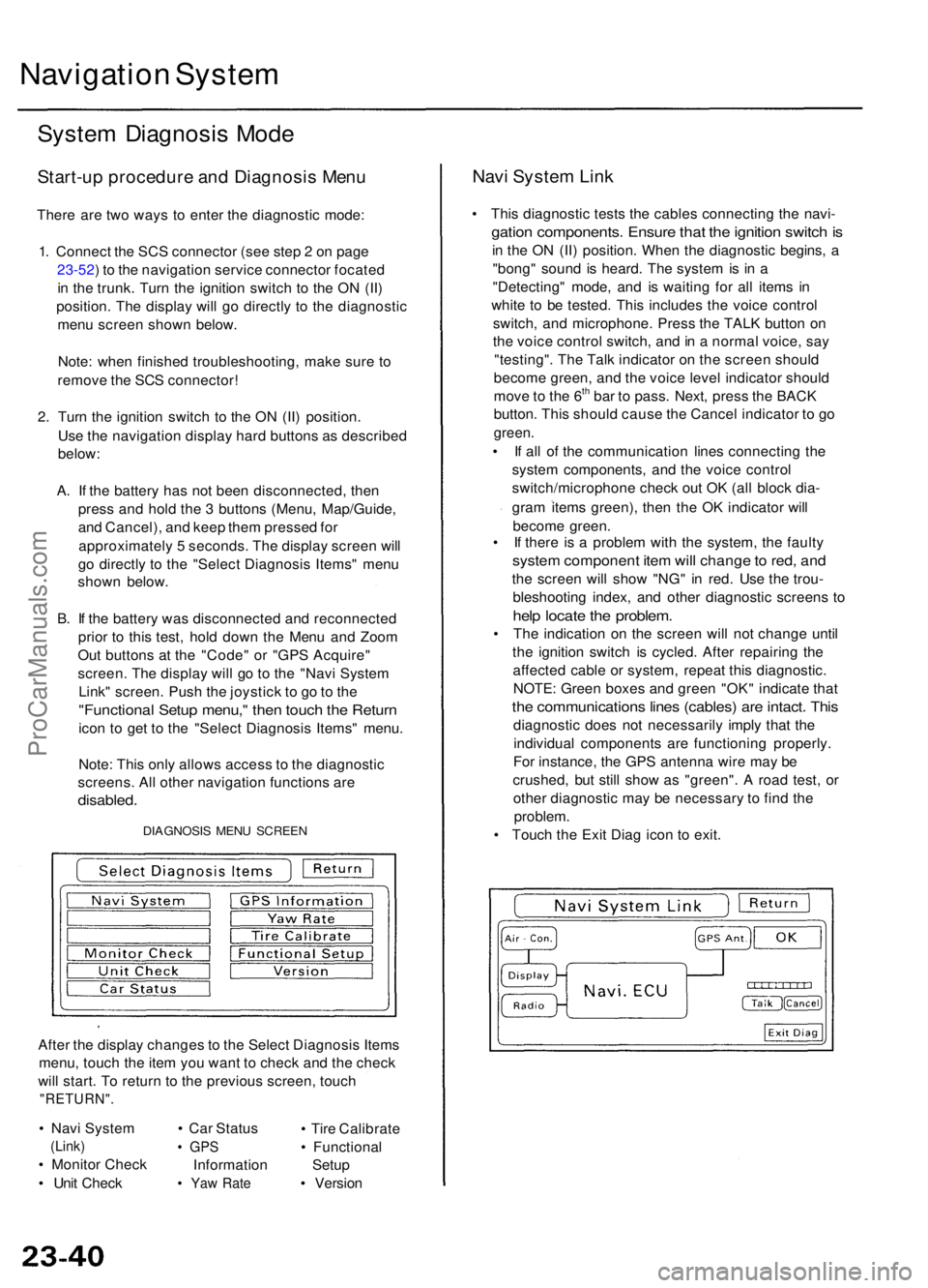
Start-u p procedur e an d Diagnosi s Men u
There ar e tw o way s t o ente r th e diagnosti c mode :
1 . Connec t th e SC S connecto r (se e ste p 2 o n pag e
23-52 ) t o th e navigatio n servic e connecto r focate d
i n th e trunk . Tur n th e ignitio n switc h t o th e O N (II )
position . Th e displa y wil l g o directl y t o th e diagnosti c
men u scree n show n below .
Note : whe n finishe d troubleshooting , mak e sur e t o
remov e th e SC S connector !
2 . Tur n th e ignitio n switc h t o th e O N (II ) position .
Us e th e navigatio n displa y har d button s a s describe d
below :
A . I f th e batter y ha s no t bee n disconnected , the n
pres s an d hol d th e 3 button s (Menu , Map/Guide ,
an d Cancel) , an d kee p the m presse d fo r
approximatel y 5 seconds . Th e displa y scree n wil l
g o directl y t o th e "Selec t Diagnosi s Items " men u
show n below .
B . I f th e batter y wa s disconnecte d an d reconnecte d
prio r t o thi s test , hol d dow n th e Men u an d Zoo m
Ou t button s a t th e "Code " o r "GP S Acquire "
screen . Th e displa y wil l g o t o th e "Nav i Syste m
Link " screen . Pus h th e joystic k t o g o to th e
"Functiona l Setu p menu, " the n touc h th e Retur n
icon t o ge t t o th e "Selec t Diagnosi s Items " menu .
Note : Thi s onl y allow s acces s t o th e diagnosti c
screens . Al l othe r navigatio n function s ar e
disabled .
DIAGNOSI S MEN U SCREE N
After th e displa y change s t o th e Selec t Diagnosi s Item s
menu , touc h th e ite m yo u wan t t o chec k an d th e chec k
wil l start . T o retur n t o th e previou s screen , touc h
"RETURN" .
• Nav i Syste m
(Link)
• Monito r Chec k
• Uni t Chec k •
Ca r Statu s
• GP S
Informatio n
• Ya w Rat e
• Tir e Calibrat e
• Functiona l
Setu p
• Versio n
Navi Syste m Lin k
• Thi s diagnosti c test s th e cable s connectin g th e navi -
gation components . Ensur e tha t th e ignitio n switc h is
in th e O N (II ) position . Whe n th e diagnosti c begins , a
"bong " soun d i s heard . Th e syste m is i n a
"Detecting " mode , an d i s waitin g fo r al l item s i n
whit e t o b e tested . Thi s include s th e voic e contro l
switch , an d microphone . Pres s th e TAL K butto n o n
th e voic e contro l switch , an d in a norma l voice , sa y
"testing" . Th e Tal k indicato r o n th e scree n shoul d
becom e green , an d th e voic e leve l indicato r shoul d
mov e to th e 6
th ba r t o pass . Next , pres s th e BAC K
button . Thi s shoul d caus e th e Cance l indicato r t o g o
green .
• I f al l o f th e communicatio n line s connectin g th e
syste m components , an d th e voic e contro l
switch/microphon e chec k ou t O K (al l bloc k dia -
gra m item s green) , the n th e O K indicato r wil l
becom e green .
• I f ther e i s a proble m wit h th e system , th e fault y
system componen t ite m wil l chang e to red , an d
the scree n wil l sho w "NG " i n red . Us e th e trou -
bleshootin g index , an d othe r diagnosti c screen s t o
hel p locat e th e problem .
• Th e indicatio n o n th e scree n wil l no t chang e unti l
th e ignitio n switc h i s cycled . Afte r repairin g th e
affecte d cabl e o r system , repea t thi s diagnostic .
NOTE : Green boxes an d gree n "OK " indicat e tha t
the communication s line s (cables ) ar e intact . Thi s
diagnosti c doe s no t necessaril y impl y tha t th e
individua l component s ar e functionin g properly .
Fo r instance , th e GP S antenn a wir e ma y b e
crushed , bu t stil l sho w a s "green" . A roa d test , o r
othe r diagnosti c ma y b e necessar y t o fin d th e
problem.
• Touc h th e Exi t Dia g ico n t o exit .
ProCarManuals.com