navigation ACURA RL KA9 1996 Service Service Manual
[x] Cancel search | Manufacturer: ACURA, Model Year: 1996, Model line: RL KA9, Model: ACURA RL KA9 1996Pages: 1954, PDF Size: 61.44 MB
Page 277 of 1954
Navigation Syste m
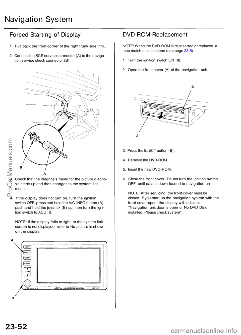
Forced Startin g o f Displa y
1. Pul l bac k th e fron t corne r o f th e righ t trun k sid e trim. .
2 . Connec t th e SC S servic e connecto r (A ) t o th e naviga -
tio n servic e chec k connecto r (B) .
3 . Chec k tha t th e diagnosi s men u fo r th e pictur e diagno -
si s start s u p an d the n change s t o th e syste m lin k
menu .
4 . I f th e displa y doe s no t tur n on , tur n th e ignitio n
switc h OFF , pres s an d hol d th e A/C-INF O butto n (A) ,
pus h an d hol d th e joystic k (B ) up , the n tur n th e igni -
tio n switc h to AC C (I) .
NOTE : I f th e displa y fail s t o light , o r th e syste m lin k
scree n is no t displayed , refe r t o N o pictur e is show n
on th e display .
DVD-RO M Replacemen t
NOTE: Whe n th e DVD-RO M is re-inserte d o r replaced , a
ma p matc h mus t b e don e (se e pag e 23-5 ).
1 . Tur n th e ignitio n switc h O N (II) .
2 . Ope n th e fron t cove r (A ) o f th e navigatio n unit .
3 . Pres s th e EJEC T butto n (B) .
4 . Remov e th e DVD-ROM .
5 . Inser t th e ne w DVD-ROM .
6 . Clos e th e fron t cover . D o no t tur n th e ignitio n switc h
OFF , unti l dat a is dow n loade d t o navigatio n unit .
NOTE : Afte r servicing , th e fron t cove r mus t b e
closed . I f yo u star t u p th e navigatio n syste m wit h th e
fron t cove r open , th e displa y wil l indicate .
"Navigatio n uni t doo r i s ope n o r N o DV D Dis k
installed . Pleas e chec k system" .
ProCarManuals.com
Page 278 of 1954
Navigation Unit Removal/
Installation
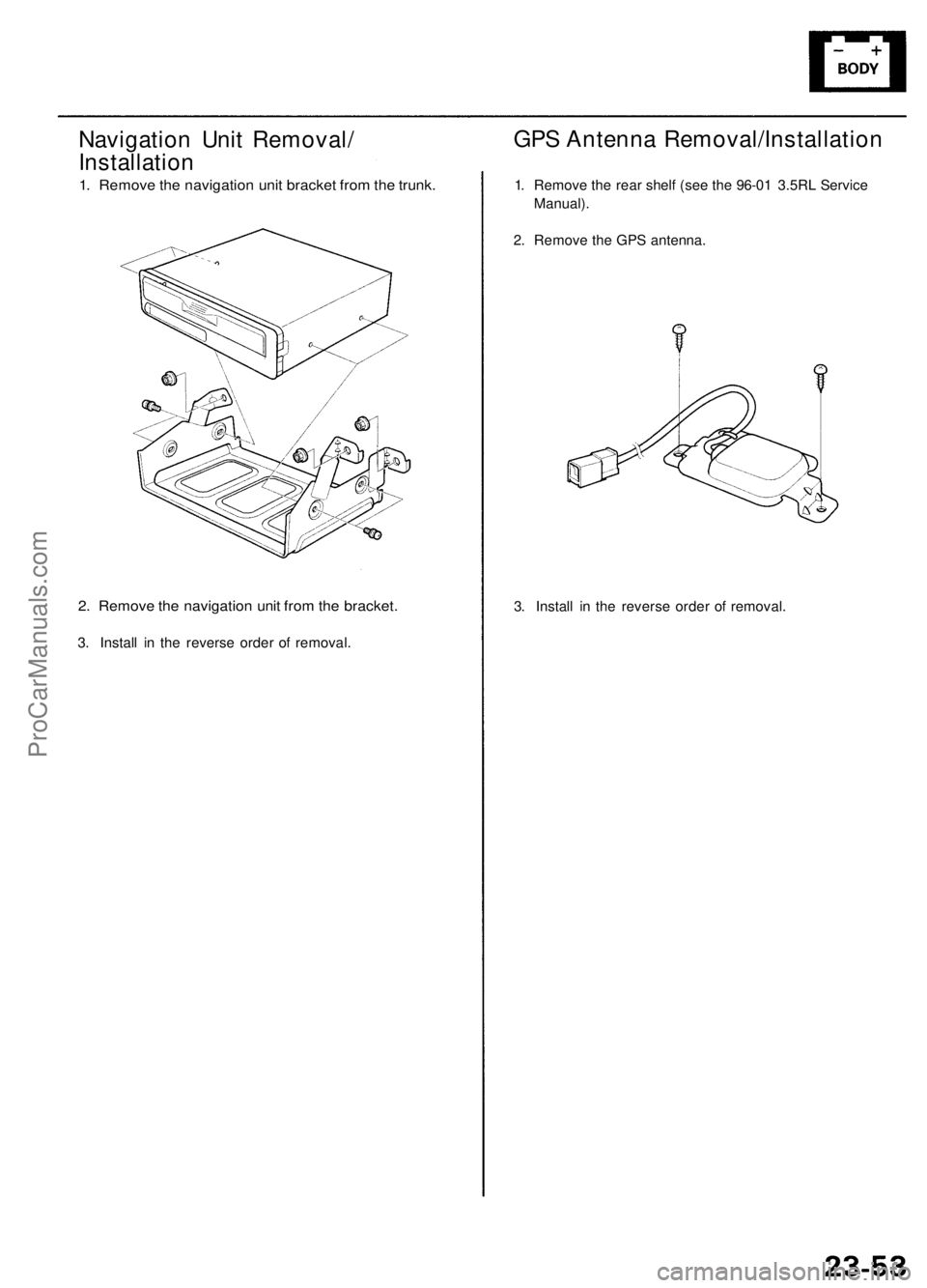
1. Remove the navigation unit bracket from the trunk.
2. Remove the navigation unit from the bracket.
3. Install in the reverse order of removal.
3. Install in the reverse order of removal.
GPS Antenna Removal/Installation
1. Remove the rear shelf (see the 96-01 3.5RL Service
Manual).
2. Remove the GPS antenna.ProCarManuals.com
Page 279 of 1954
Navigation Syste m
Display Uni t Removal/Installatio n
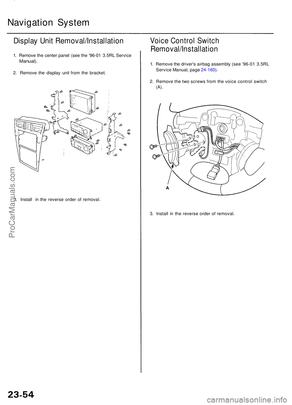
1. Remov e th e cente r pane l (se e th e '96-0 1 3.5R L Servic e
Manual) .
2. Remov e th e displa y uni t fro m th e bracket .
3 . Instal l i n th e revers e orde r o f removal .
3. Instal l i n th e revers e orde r o f removal .
Voice Contro l Switc h
Removal/Installatio n
1. Remov e th e driver' s airba g assembl y (se e '96-0 1 3.5R L
Servic e Manual , pag e 24-160 ).
2 . Remov e th e tw o screw s fro m th e voic e contro l switc h
(A).
ProCarManuals.com
Page 1730 of 1954
Navigation Functio n
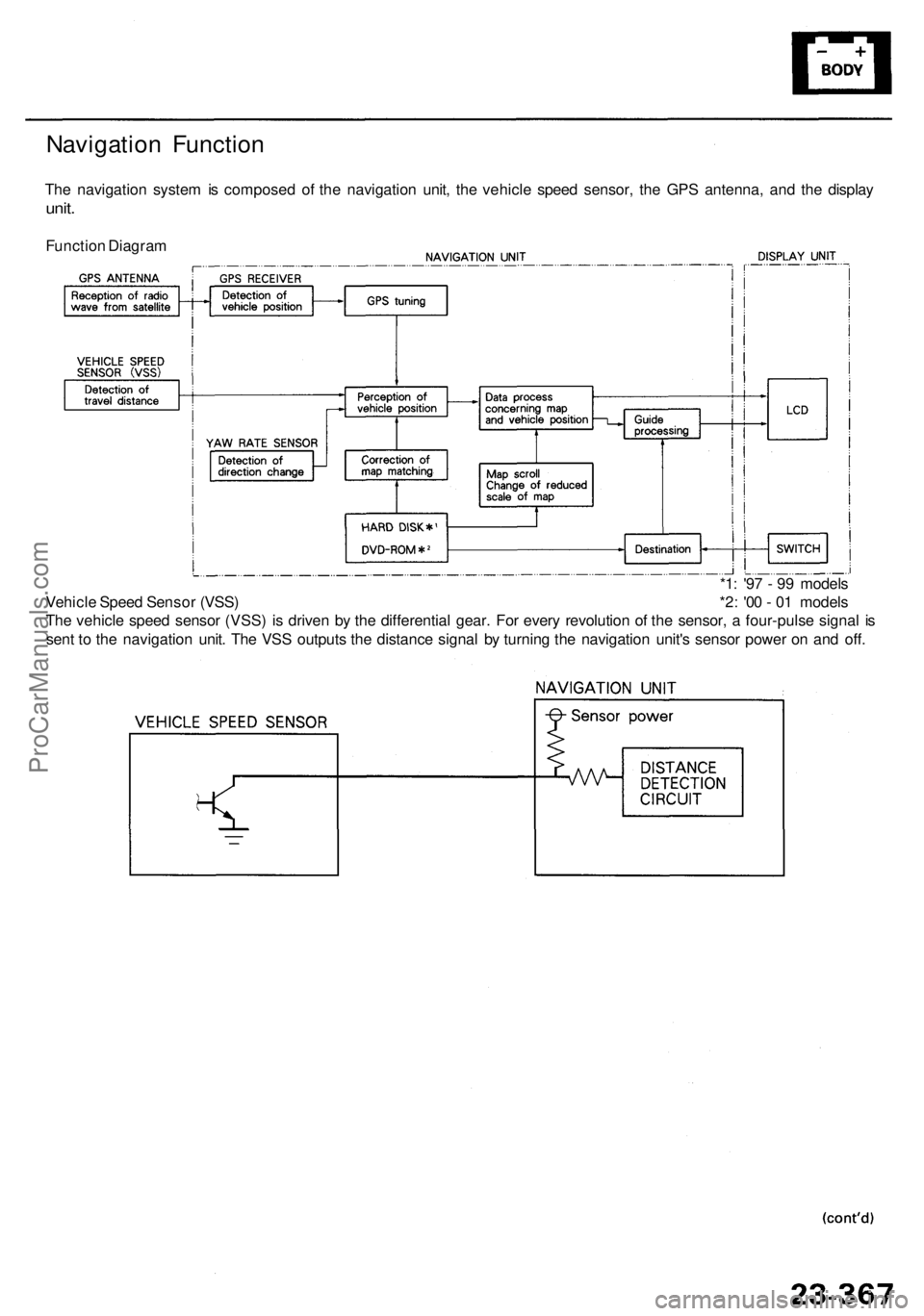
The navigatio n syste m is compose d o f th e navigatio n unit , th e vehicl e spee d sensor , th e GP S antenna , an d th e displa y
unit.
Functio n Diagra m
*1: '9 7 - 9 9 model s
Vehicl e Spee d Senso r (VSS ) *2 : '0 0 - 0 1 model s
Th e vehicl e spee d senso r (VSS ) i s drive n b y th e differentia l gear . Fo r ever y revolutio n o f th e sensor , a four-puls e signa l i s
sen t t o th e navigatio n unit . Th e VS S output s th e distanc e signa l b y turnin g th e navigatio n unit' s senso r powe r o n an d off .
ProCarManuals.com
Page 1731 of 1954
Description
Navigation Functio n (cont'd )
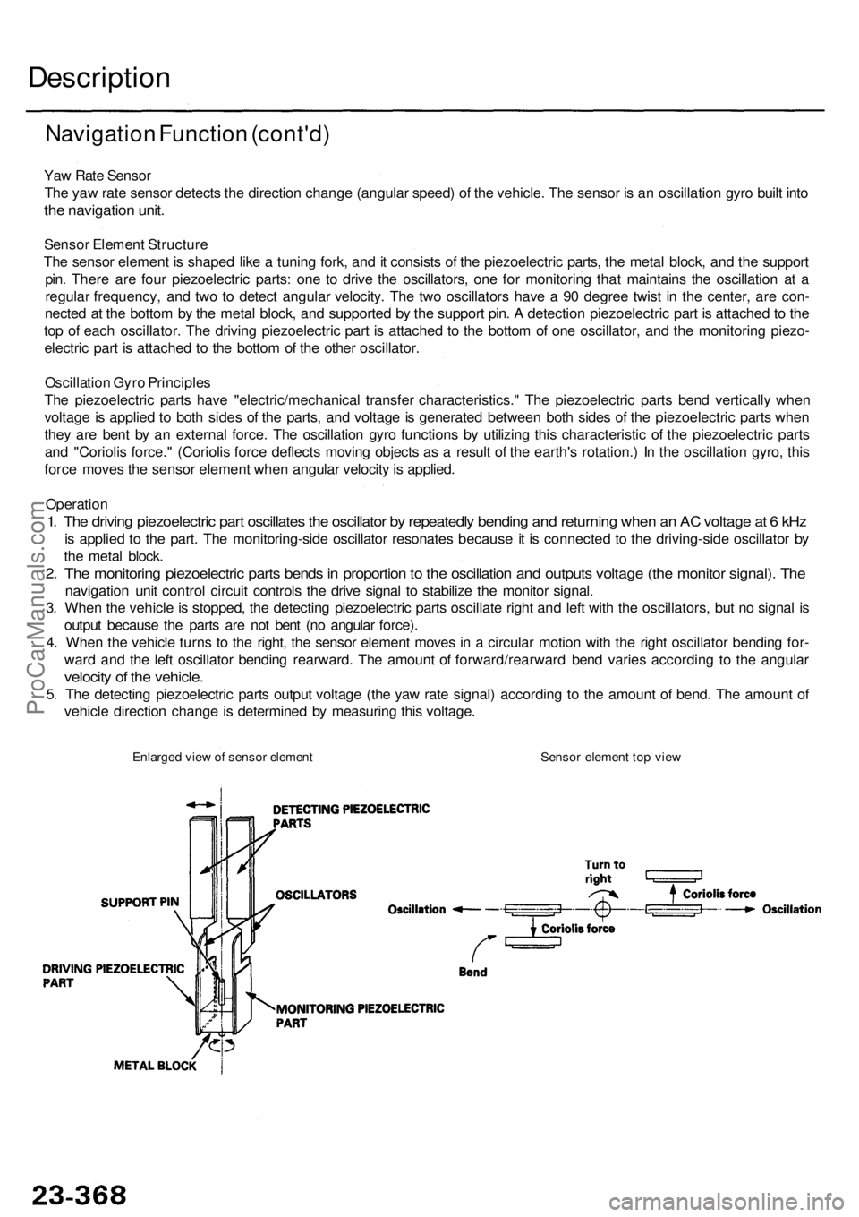
Yaw Rat e Senso r
Th e ya w rat e senso r detect s th e directio n chang e (angula r speed ) o f th e vehicle . Th e senso r i s a n oscillatio n gyr o buil t int o
the navigatio n unit .
Senso r Elemen t Structur e
Th e senso r elemen t i s shape d lik e a tunin g fork , an d it consist s o f th e piezoelectri c parts , th e meta l block , an d th e suppor t
pin . Ther e ar e fou r piezoelectri c parts : on e t o driv e th e oscillators , on e fo r monitorin g tha t maintain s th e oscillatio n a t a
regula r frequency , an d tw o t o detec t angula r velocity . Th e tw o oscillator s hav e a 90 degre e twis t i n th e center , ar e con -
necte d a t th e botto m b y th e meta l block , an d supporte d b y th e suppor t pin . A detectio n piezoelectri c par t i s attache d to th e
to p o f eac h oscillator . Th e drivin g piezoelectri c par t i s attache d t o th e botto m o f on e oscillator , an d th e monitoring piezo-
electri c par t i s attache d t o th e botto m o f th e othe r oscillator .
Oscillatio n Gyr o Principle s
Th e piezoelectri c part s hav e "electric/mechanica l transfe r characteristics. " Th e piezoelectri c part s ben d verticall y whe n
voltag e is applie d t o bot h side s o f th e parts , an d voltag e is generate d betwee n bot h side s o f th e piezoelectri c part s whe n
the y ar e ben t b y a n externa l force . Th e oscillatio n gyr o function s b y utilizin g thi s characteristi c o f th e piezoelectri c part s
an d "Corioli s force. " (Corioli s forc e deflect s movin g object s a s a resul t o f th e earth' s rotation. ) I n th e oscillation gyro, thi s
forc e move s th e senso r elemen t whe n angula r velocit y is applied .
Operatio n
1. Th e drivin g piezoelectri c par t oscillate s th e oscillato r b y repeatedl y bendin g an d returnin g whe n a n A C voltag e a t 6 kH z
is applie d t o th e part . Th e monitoring-sid e oscillato r resonate s becaus e it i s connecte d t o th e driving-sid e oscillato r b y
th e meta l block .
2. Th e monitorin g piezoelectri c part s bend s in proportio n to th e oscillatio n an d output s voltag e (th e monito r signal) . Th e
navigatio n uni t contro l circui t control s th e driv e signa l t o stabiliz e th e monito r signal .
3 . Whe n th e vehicl e is stopped , th e detectin g piezoelectri c part s oscillat e righ t an d lef t wit h th e oscillators , bu t n o signa l i s
outpu t becaus e th e part s ar e no t ben t (n o angula r force) .
4 . Whe n th e vehicl e turn s t o th e right , th e senso r elemen t move s i n a circula r motio n wit h th e righ t oscillato r bendin g for -
war d an d th e lef t oscillato r bendin g rearward . Th e amoun t o f forward/rearwar d ben d varie s accordin g t o th e angula r
velocity o f th e vehicle .
5. Th e detectin g piezoelectri c part s outpu t voltag e (th e ya w rat e signal ) accordin g t o th e amoun t o f bend . Th e amoun t o f
vehicl e directio n chang e is determine d b y measurin g thi s voltage .
Enlarged vie w o f senso r elemen t Senso r elemen t to p vie w
ProCarManuals.com
Page 1733 of 1954
Description
Navigation Functio n (cont'd )
Navigatio n Uni t
Th e navigatio n uni t calculate s th e vehicl e positio n an d guide s yo u t o th e destination . Th e uni t perform s ma p matchin g
correction , GP S correction , an d distanc e tuning . I t als o control s th e men u function s an d th e DVD-RO M driv e (har d dis k
drive '9 6 - 9 9 models) . Wit h contro l o f al l thes e items , th e navigatio n uni t make s th e navigatio n pictur e signal , the n it
transmit s th e signa l t o th e displa y uni t an d audi o drivin g instruction s t o th e audi o unit .
Calculatio n o f Vehicl e Positio n
Th e navigatio n uni t calculate s th e vehicl e positio n (th e drivin g directio n an d th e curren t position ) b y receivin g th e direc -
tiona l chang e signal s fro m th e ya w rat e senso r an d th e trave l distanc e signal s fro m th e vehicl e spee d senso r (VSS) .
Ma p Matchin g Tunin g
Th e ma p matchin g tunin g i s accomplishe d b y indicatin g th e vehicl e positio n o n th e road s o n th e map . Th e ma p dat a
transmitte d fro m th e DVD-RO M (har d dis k '9 6 - 9 9 models ) i s checke d agains t th e vehicl e positio n data , an d th e vehicl e
positio n i s indicate d o n th e neares t road . Ma p matchin g tunin g doe s no t occu r whe n th e vehicl e travel s o n a roa d no t
show n o n th e ma p o r whe n th e vehicl e positio n is fa r awa y fro m a roa d o n th e map .
GP S Tunin g
Th e GP S tunin g is accomplishe d b y indicatin g th e vehicl e positio n a s th e GPS' s vehicl e position . Th e navigatio n uni t com -
pare s it s calculate d vehicl e positio n dat a wit h th e GP S vehicl e positio n data . I f ther e i s larg e differenc e betwee n th e two ,
th e indicate d vehicl e positio n i s adjuste d to th e GP S vehicl e position .
Distanc e Tunin g
Th e distanc e tunin g reduce s th e differenc e betwee n th e trave l distanc e signa l fro m th e VS S an d th e distanc e dat a o n th e
map . Th e navigatio n uni t compare s it s calculate d vehicl e positio n dat a wit h th e GP S vehicl e positio n data . Th e navigatio n
uni t the n decreases the tunin g valu e whe n th e vehicl e positio n i s ahea d o f th e GP S vehicl e position , an d i t increase s th e
tunin g valu e whe n th e vehicl e positio n is behin d th e GP S vehicl e position .
Rout e Guidanc e
Th e navigatio n uni t ca n calculat e differen t route s t o a selecte d destination . Yo u hav e fou r options :
• Direct Rout e — Calculat e a route that is th e mos t direc t and will tak e the leas t time .
• Eas y Rout e — Calculat e a rout e tha t minimize s th e numbe r o f turn s needed .
• Minimiz e Freeway s — Calculat e a rout e tha t avoid s freewa y travel . I f tha t i s no t possible , kee p th e amoun t o f freewa y
trave l t o a minimum .
• Minimiz e Tol l Road s — Calculat e a rout e tha t avoid s o r minimize s trave l o n tol l road s
Audi o Guidanc e
Th e navigatio n uni t transmit s audi o drivin g instruction s befor e enterin g a n intersectio n o r passin g a junction .
Th e audi o instruction s com e throug h audi o uni t an d th e fron t speakers .
DVD-RO M ('0 0 - 0 1 models) . Har d Dis k ('9 6 - 9 9 models )
Th e ma p dat a (includin g al l scal e rates ) i s store d in th e DVD-ROM/Har d Disk . Th e ma p dat a includes :
• Roa d distances , roa d widths , spee d limits , traffi c regulations , passin g tim e a t junction , distance s t o junctions , an d th e
drivin g instruction s fo r audi o guidance .
• Latitud e an d longitud e fo r GPS .
ProCarManuals.com
Page 1736 of 1954
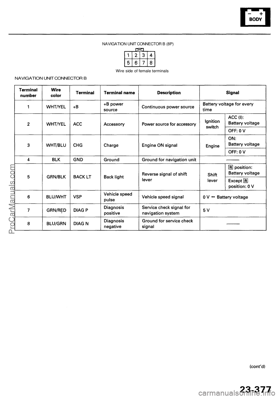
NAVIGATION UNI T CONNECTO R B (8P )
NAVIGATIO N UNI T CONNECTO R B
Wir e sid e o f femal e terminal s
ProCarManuals.com
Page 1740 of 1954
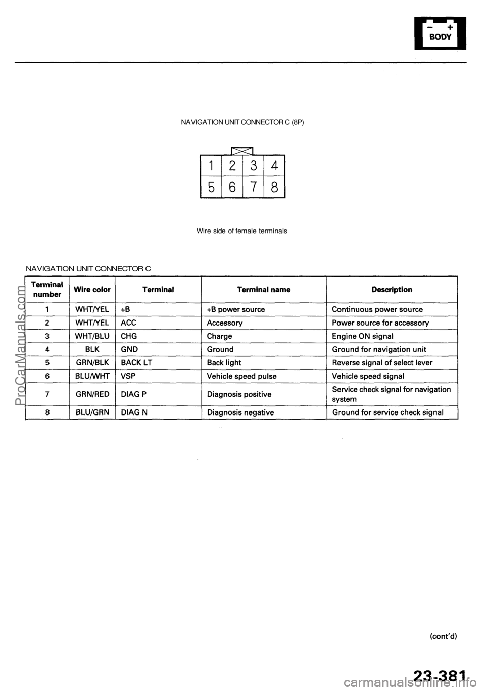
NAVIGATION UNI T CONNECTO R C (8P )
Wir e sid e o f femal e terminal s
NAVIGATIO N UNI T CONNECTO R C
ProCarManuals.com
Page 1770 of 1954
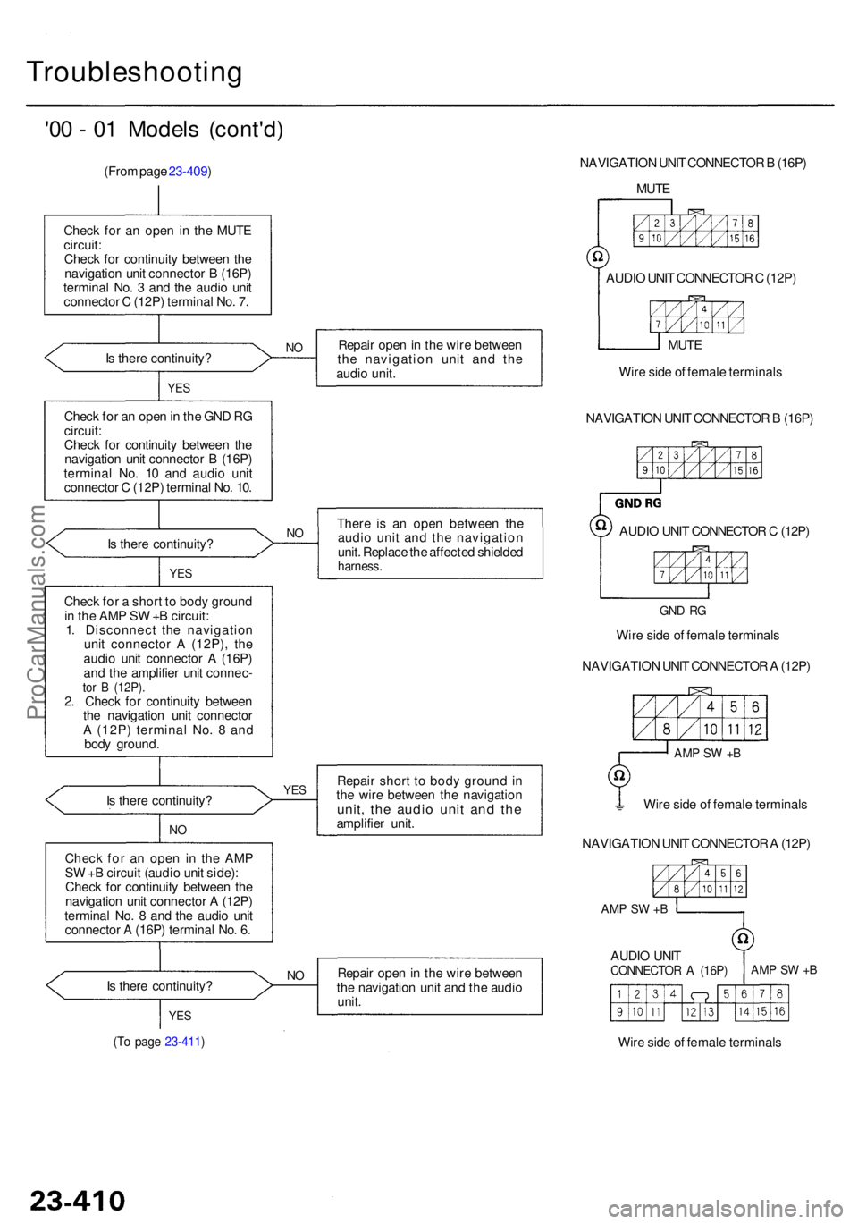
(To pag e 23-411 )
YES
Is ther e continuity ?NORepai r ope n in th e wir e betwee n
th e navigatio n uni t an d th e audi o
unit .
Chec
k fo r a n ope n i n th e AM P
S W +B circui t (audi o uni t side) :
Chec k fo r continuit y betwee n th e
navigatio n uni t connecto r A (12P )
termina l No . 8 an d th e audi o uni t
connecto r A (16P ) termina l No . 6 .
I
s ther e continuity ? Repai
r shor t t o bod y groun d in
th e wir e betwee n th e navigatio n
unit, th e audi o uni t an d th eamplifie r unit .
YES
NO
Chec k fo r a shor t t o bod y groun d
i n th e AM P S W +B circuit :
1 . Disconnec t th e navigatio n
uni t connecto r A (12P) , th e
audi o uni t connecto r A (16P )
an d th e amplifie r uni t connec -
tor B (12P) .2. Chec k fo r continuit y betwee n
th e navigatio n uni t connecto r
A (12P ) termina l No . 8 an d
bod y ground .
I
s ther e continuity ? Ther
e i s a n ope n betwee n th e
audi o uni t an d th e navigatio n
unit . Replac e th e affecte d shielde d
harness .
Check fo r a n ope n in th e GN D R G
circuit :
Chec k fo r continuit y betwee n th e
navigatio n uni t connecto r B (16P )
termina l No . 1 0 an d audi o uni t
connecto r C (12P ) termina l No . 10 .
NO
YE S
Repai r ope n in th e wir e betwee n
th e navigatio n uni t an d th e
audi o unit .NOIs ther e continuity ?
YES
Chec k fo r a n ope n in th e MUT Ecircuit :Check fo r continuit y betwee n th e
navigatio n uni t connecto r B (16P )
termina l No . 3 an d th e audi o uni t
connecto r C (12P ) termina l No . 7 .
(Fro
m pag e 23-409 )
'00 - 0 1 Model s (cont'd )
Troubleshootin g
NAVIGATION UNI T CONNECTO R B (16P )
MUT E
AUDI O UNI T CONNECTO R C (12P )
MUT E
Wir e sid e o f femal e terminal s
NAVIGATIO N UNI T CONNECTO R B (16P )
AUDI O UNI T CONNECTO R C (12P )
NAVIGATIO N UNI T CONNECTO R A (12P )
Wir
e sid e o f femal e terminal s
GND R G
Wir e sid e o f femal e terminal s
NAVIGATIO N UNI T CONNECTO R A (12P )
AUDI O UNI T
CONNECTO R A (16P )AMP S W +B
AM P S W +B
Wir e sid e o f femal e terminal s
AMP S W +B
ProCarManuals.com