reset ACURA RL KA9 1996 Service Owner's Manual
[x] Cancel search | Manufacturer: ACURA, Model Year: 1996, Model line: RL KA9, Model: ACURA RL KA9 1996Pages: 1954, PDF Size: 61.44 MB
Page 589 of 1954
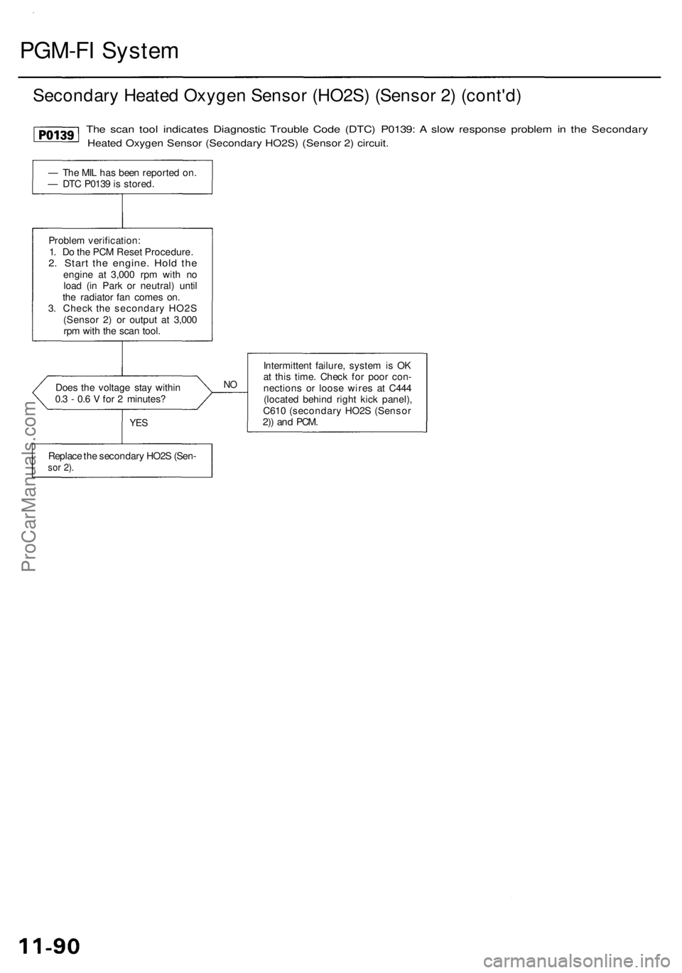
PGM-FI System
Secondary Heated Oxygen Sensor (HO2S) (Sensor 2) (cont'd)
Does the voltage stay within
0.3 - 0.6 V for 2 minutes?
NO
Intermittent failure, system is OK
at this time. Check for poor con-
nections or loose wires at C444
(located behind right kick panel),
C610 (secondary HO2S (Sensor
2)) and
PCM.
The scan tool indicates Diagnostic Trouble Code (DTC) P0139: A slow response problem in the Secondary
Heated Oxygen Sensor (Secondary HO2S) (Sensor 2) circuit.
— The MIL has been reported on.
— DTC P0139 is stored.
Problem verification:
1. Do the PCM Reset Procedure.
2. Start the engine. Hold the
engine at 3,000 rpm with no
load (in Park or neutral) until
the radiator fan comes on.
3. Check the secondary HO2S
(Sensor 2) or output at 3,000
rpm with the scan tool.
Replace the secondary HO2S (Sen-
sor 2).
YESProCarManuals.com
Page 624 of 1954
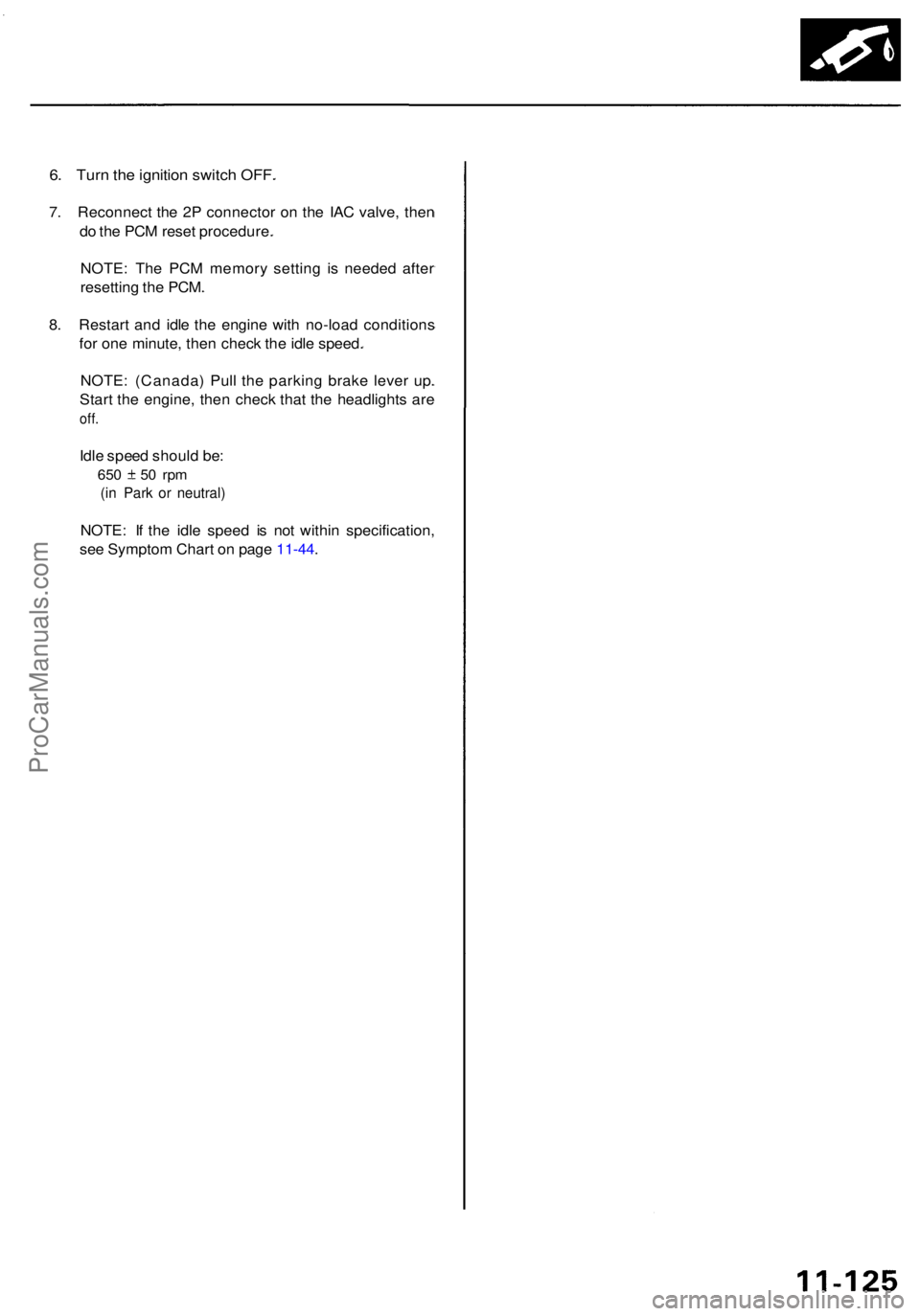
6. Tur n th e ignitio n switc h OFF .
7. Reconnec t th e 2 P connecto r o n th e IA C valve , the n
d o th e PC M rese t procedure .
NOTE : Th e PC M memor y settin g i s neede d afte r
resettin g th e PCM .
8 . Restar t an d idl e th e engin e wit h no-loa d condition s
fo r on e minute , the n chec k th e idl e speed .
NOTE : (Canada ) Pul l th e parkin g brak e leve r up .
Star t th e engine , the n chec k tha t th e headlight s ar e
off.
Idle spee d shoul d be :
650 5 0 rp m
(in Par k o r neutral )
NOTE: I f th e idl e spee d i s no t withi n specification ,
se e Sympto m Char t o n pag e 11-44 .
ProCarManuals.com
Page 625 of 1954
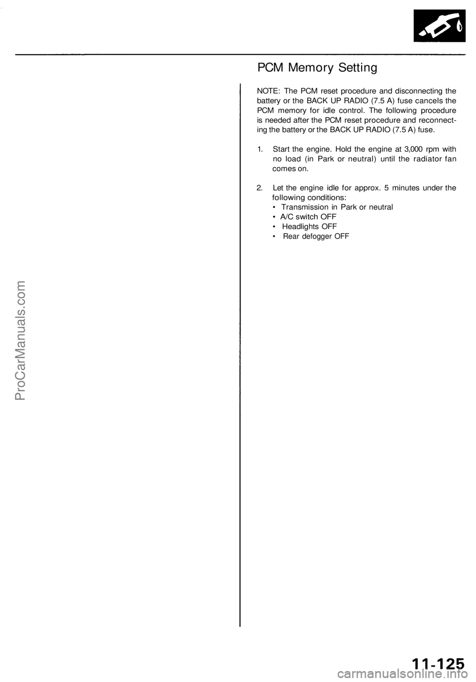
PCM Memory Setting
NOTE: The PCM reset procedure and disconnecting the
battery or the BACK UP RADIO (7.5 A) fuse cancels the
PCM memory for idle control. The following procedure
is needed after the PCM reset procedure and reconnect-
ing the battery or the BACK UP RADIO (7.5 A) fuse.
1. Start the engine. Hold the engine at 3,000 rpm with
no load (in Park or neutral) until the radiator fan
comes on.
2. Let the engine idle for approx. 5 minutes under the
following conditions:
• Transmission in Park or neutral
• A/C switch OFF
• Headlights OFF
• Rear defogger OFFProCarManuals.com
Page 632 of 1954
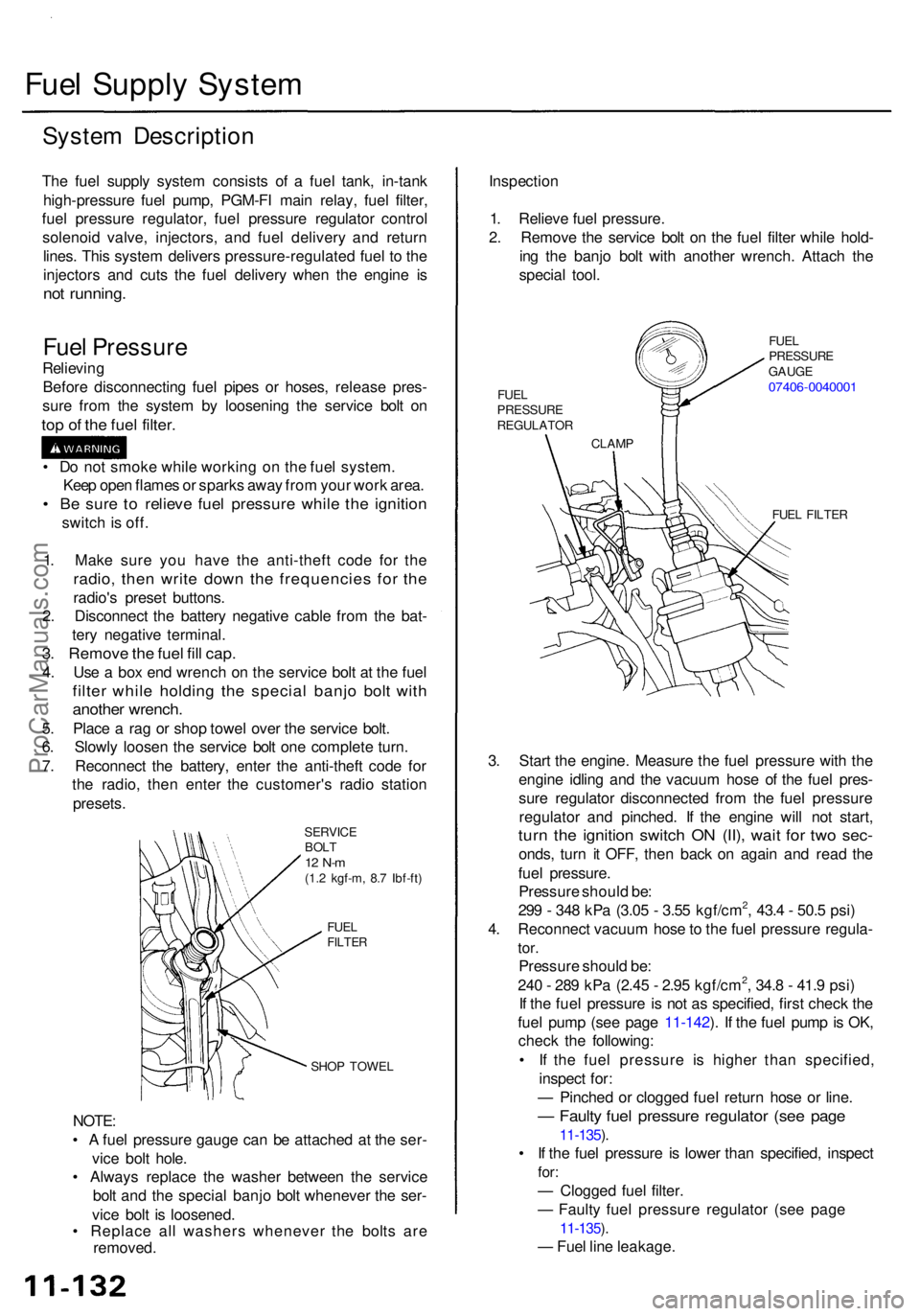
Fuel Suppl y Syste m
System Descriptio n
The fue l suppl y syste m consist s o f a fue l tank , in-tan k
high-pressur e fue l pump , PGM-F I mai n relay , fue l filter ,
fue l pressur e regulator , fue l pressur e regulato r contro l
solenoi d valve , injectors , an d fue l deliver y an d retur n
lines . Thi s syste m deliver s pressure-regulate d fue l t o th e
injector s an d cut s th e fue l deliver y whe n th e engin e i s
no t running .
Fuel Pressur e
Relieving
Befor e disconnectin g fue l pipe s o r hoses , releas e pres -
sur e fro m th e syste m b y loosenin g th e servic e bol t o n
top o f th e fue l filter .
SERVIC E
BOL T
12 N- m(1.2 kgf-m , 8. 7 Ibf-ft )
FUE L
FILTE R
SHOP TOWE L
NOTE:
• A fue l pressur e gaug e can be attache d a t th e ser -
vic e bol t hole .
• Alway s replac e th e washe r betwee n th e servic e
bol t an d th e specia l banj o bol t wheneve r th e ser -
vic e bol t i s loosened .
• Replac e al l washer s wheneve r th e bolt s ar e
removed . Inspectio
n
1 . Reliev e fue l pressure .
2 . Remov e th e servic e bol t o n th e fue l filte r whil e hold -
in g th e banj o bol t wit h anothe r wrench . Attac h th e
specia l tool .
FUEL FILTE R
3. Star t th e engine . Measur e th e fue l pressur e wit h th e
engin e idlin g an d th e vacuu m hos e o f th e fue l pres -
sur e regulato r disconnecte d fro m th e fue l pressur e
regulato r an d pinched . I f th e engin e wil l no t start ,
turn th e ignitio n switc h O N (II) , wai t fo r tw o sec -
onds , tur n i t OFF , the n bac k o n agai n an d rea d th e
fue l pressure .
Pressur e shoul d be :
29 9 - 34 8 kP a (3.0 5 - 3.5 5 kgf/cm
2, 43. 4 - 50. 5 psi )
4 . Reconnec t vacuu m hos e to th e fue l pressur e regula -
tor.
Pressur e shoul d be :
24 0 - 28 9 kP a (2.4 5 - 2.9 5 kgf/cm2, 34. 8 - 41. 9 psi )
I f th e fue l pressur e i s no t a s specified , firs t chec k th e
fue l pum p (se e pag e 11-142 ). I f th e fue l pum p is OK ,
chec k th e following :
• I f th e fue l pressur e i s highe r tha n specified ,
inspec t for :
— Pinche d o r clogge d fue l retur n hos e o r line .
— Fault y fue l pressur e regulato r (se e pag e
11-135 ).
• I f th e fue l pressur e i s lowe r tha n specified , inspec t
for:
— Clogge d fue l filter .
— Fault y fue l pressur e regulato r (se e pag e
11-135 ).
— Fue l lin e leakage .
1
. Mak e sur e yo u hav e th e anti-thef t cod e fo r th e
radio , the n writ e dow n th e frequencie s fo r th e
radio' s prese t buttons .
2 . Disconnec t th e batter y negativ e cabl e fro m th e bat -
ter y negativ e terminal .
3. Remov e th e fue l fil l cap .
4. Us e a bo x en d wrenc h o n th e servic e bol t a t th e fue l
filte r whil e holdin g th e specia l banj o bol t wit h
anothe r wrench .
5. Plac e a ra g o r sho p towe l ove r th e servic e bolt .
6 . Slowl y loose n th e servic e bol t on e complet e turn .
7 . Reconnec t th e battery , ente r th e anti-thef t cod e fo r
th e radio , the n ente r th e customer' s radi o statio n
presets .
•
D o no t smok e whil e workin g o n th e fue l system .
Kee p ope n flame s o r spark s awa y fro m you r wor k area .
• B e sur e t o reliev e fue l pressur e whil e th e ignitio n
switch is off .
CLAM P
FUE
L
PRESSUR E
REGULATO R FUE
L
PRESSUR E
GAUG E
07406-004000 1
ProCarManuals.com
Page 671 of 1954
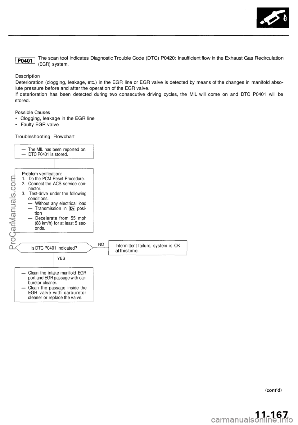
The scan tool indicates Diagnostic Trouble Code (DTC) P0420: Insufficient flow in the Exhaust Gas Recirculation
(EGR)
system.
Description
Deterioration (clogging, leakage, etc.) in the EGR line or EGR valve is detected by means of the changes in manifold abso-
lute pressure before and after the operation of the EGR valve.
If deterioration has been detected during two consecutive driving cycles, the MIL will come on and DTC P0401 will be
stored.
Possible Causes
• Clogging, leakage in the EGR line
• Faulty EGR valve
Troubleshooting Flowchart
Is DTC P0401 indicated?
Intermittent failure, system is OK
at this time.
YES
Clean the intake manifold EGR
port and EGR passage with car-
buretor cleaner.
Clean the passage inside the
EGR valve with carburetor
cleaner or replace the valve.
NO
Problem verification:
1. Do the PCM Reset Procedure.
2. Connect the ACS service con-
nector.
3. Test-drive under the following
conditions.
— Without any electrical load
— Transmission in posi-
tion
— Decelerate from 55 mph
(88 km/h) for at least 5 sec-
onds.
The MIL has been reported on.
DTC P0401 is stored.ProCarManuals.com
Page 759 of 1954
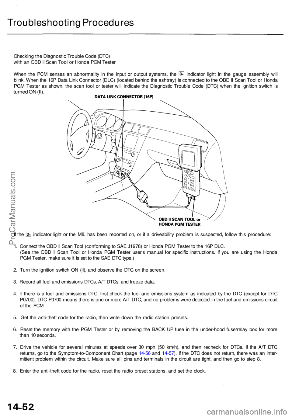
Troubleshooting Procedure s
Checking th e Diagnosti c Troubl e Cod e (DTC )
wit h a n OB D II Sca n Too l o r Hond a PG M Teste r
When th e PC M sense s a n abnormalit y i n th e inpu t o r outpu t systems , th e indicato r ligh t i n th e gaug e assembl y wil l
blink . Whe n th e 16 P Dat a Lin k Connecto r (DLC ) (locate d behin d th e ashtray ) i s connecte d to th e OB D II Sca n Too l o r Hond a
PG M Teste r a s shown , th e sca n too l o r teste r wil l indicat e th e Diagnosti c Troubl e Cod e (DTC ) whe n th e ignitio n switc h i s
turne d O N (II) .
If th e indicato r ligh t o r th e MI L ha s bee n reporte d on , o r i f a driveabilit y proble m is suspected , follo w thi s procedure :
1 . Connec t th e OB D II Sca n Too l (conformin g to SA E J1978 ) o r Hond a PG M Teste r t o th e 16 P DLC .
(Se e th e OB D II Sca n Too l o r Hond a PG M Teste r user' s manua l fo r specifi c instructions . I f yo u ar e usin g th e Hond a
PG M Tester , mak e sur e it i s se t t o th e SA E DT C type. )
2 . Tur n th e ignitio n switc h O N (II) , an d observ e th e DT C o n th e screen .
3 . Recor d al l fue l an d emission s DTCs , A/ T DTCs , an d freez e data .
4 . I f ther e is a fue l an d emission s DTC , firs t chec k th e fue l an d emission s syste m a s indicate d b y th e DT C (excep t fo r DT C
P0700) . DT C P070 0 mean s ther e is on e o r mor e A/ T DTC , an d n o problem s wer e detecte d in th e fue l an d emission s circui t
of th e PCM .
5. Ge t th e anti-thef t cod e fo r th e radio , the n writ e dow n th e radi o statio n presets .
6 . Rese t th e memor y wit h th e PG M Teste r o r b y removin g th e BAC K U P fus e i n th e under-hoo d fuse/rela y bo x fo r mor e
tha n 1 0 seconds .
7 . Driv e th e vehicl e fo r severa l minute s a t speed s ove r 3 0 mp h (5 0 km/h) , an d the n rechec k fo r DTCs . I f th e A/ T DT C
returns , g o t o th e Symptom-to-Componen t Char t (pag e 14-5 6 an d 14-57 ). I f th e DT C doe s no t return , ther e wa s a n inter -
mitten t proble m withi n th e circuit . Mak e sur e al l pin s an d terminal s i n th e circui t ar e tight , an d the n g o t o ste p 8 .
8 . Ente r th e anti-thef t cod e fo r th e radio , rese t th e radi o prese t stations , an d se t th e clock .
ProCarManuals.com
Page 760 of 1954
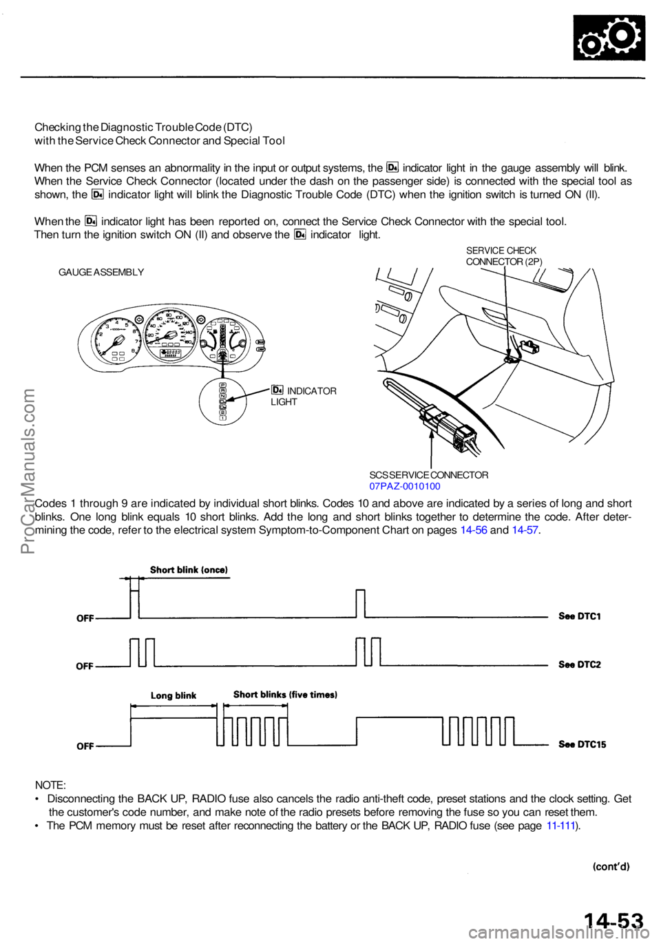
Checking th e Diagnosti c Troubl e Cod e (DTC )
wit h th e Servic e Chec k Connecto r an d Specia l Too l
Whe n th e PC M sense s a n abnormalit y in th e inpu t o r outpu t systems , th e indicato r ligh t i n th e gaug e assembl y wil l blink .
Whe n th e Servic e Chec k Connecto r (locate d unde r th e das h o n th e passenge r side ) i s connecte d wit h th e specia l too l a s
shown , th e indicato r ligh t wil l blin k th e Diagnosti c Troubl e Cod e (DTC ) whe n th e ignitio n switc h i s turne d O N (II) .
Whe n th e indicato r ligh t ha s bee n reporte d on , connec t th e Servic e Chec k Connecto r wit h th e specia l tool .
Then tur n th e ignitio n switc h O N (II ) an d observ e th e indicato r light .
INDICATO RLIGHT
Code s 1 throug h 9 ar e indicate d b y individua l shor t blinks . Code s 1 0 an d abov e ar e indicate d b y a serie s o f lon g an d shor t
blinks . On e lon g blin k equal s 1 0 shor t blinks . Ad d th e lon g an d shor t blink s togethe r t o determin e th e code . Afte r deter -
minin g th e code , refe r t o th e electrica l syste m Symptom-to-Componen t Char t o n page s 14-5 6 an d 14-57 .
NOTE :
• Disconnectin g th e BAC K UP , RADI O fus e als o cancel s th e radi o anti-thef t code , prese t station s an d th e cloc k setting . Ge t
th e customer' s cod e number , an d mak e not e o f th e radi o preset s befor e removin g th e fus e s o yo u ca n rese t them .
• Th e PC M memor y mus t b e rese t afte r reconnectin g th e batter y o r th e BAC K UP , RADI O fus e (se e pag e 11-111 ).
SC S SERVIC E CONNECTO R07PAZ-001010 0
GAUGE ASSEMBL Y
SERVICE CHEC KCONNECTO R (2P )
ProCarManuals.com
Page 762 of 1954
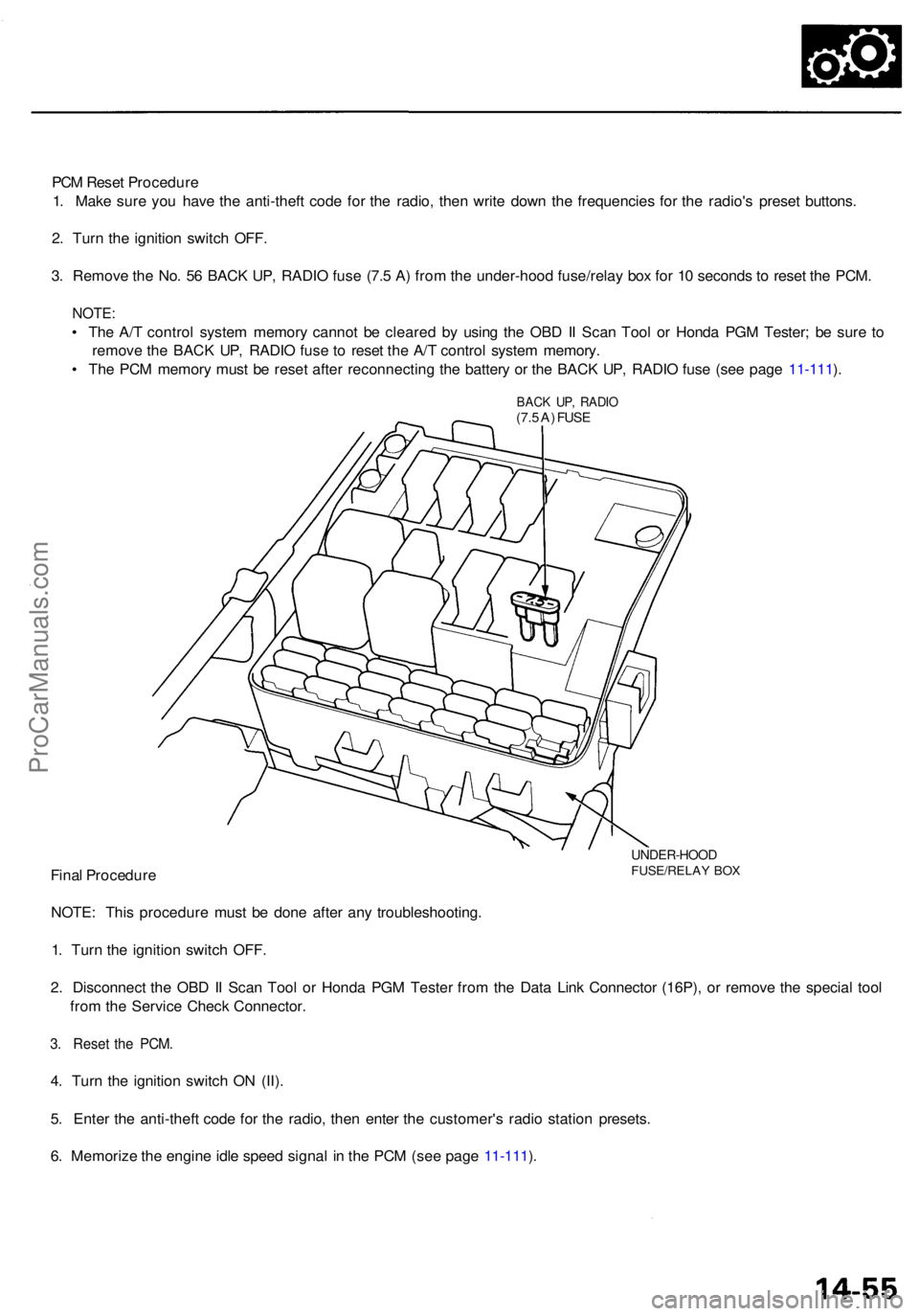
PCM Rese t Procedur e
1 . Mak e sur e yo u hav e th e anti-thef t cod e fo r th e radio , the n writ e dow n th e frequencie s fo r th e radio' s prese t buttons .
2 . Tur n th e ignitio n switc h OFF .
3 . Remov e th e No . 5 6 BAC K UP , RADI O fus e (7. 5 A ) fro m th e under-hoo d fuse/rela y bo x fo r 1 0 second s t o rese t th e PCM .
NOTE :
• Th e A/ T contro l syste m memor y canno t b e cleare d b y usin g th e OB D II Sca n Too l o r Hond a PG M Tester ; b e sur e t o
remov e th e BAC K UP , RADI O fus e t o rese t th e A/ T contro l syste m memory .
• Th e PC M memor y mus t b e rese t afte r reconnectin g th e batter y o r th e BAC K UP , RADI O fus e (se e pag e 11-111 ).
BAC K UP , RADI O(7.5 A ) FUS E
UNDER-HOO DFUSE/RELAY BO XFina l Procedur e
NOTE : Thi s procedur e mus t b e don e afte r an y troubleshooting .
1 . Tur n th e ignitio n switc h OFF .
2 . Disconnec t th e OB D II Sca n Too l o r Hond a PG M Teste r fro m th e Dat a Lin k Connecto r (16P) , o r remov e th e specia l too l
fro m th e Servic e Chec k Connector .
3. Rese t th e PCM .
4. Tur n th e ignitio n switc h O N (II) .
5 . Ente r th e anti-thef t cod e fo r th e radio , the n ente r th e customer' s radi o statio n presets .
6 . Memoriz e th e engin e idl e spee d signa l i n th e PC M (se e pag e 11-111 ).
ProCarManuals.com
Page 903 of 1954
Transmission
Installation (cont'd )
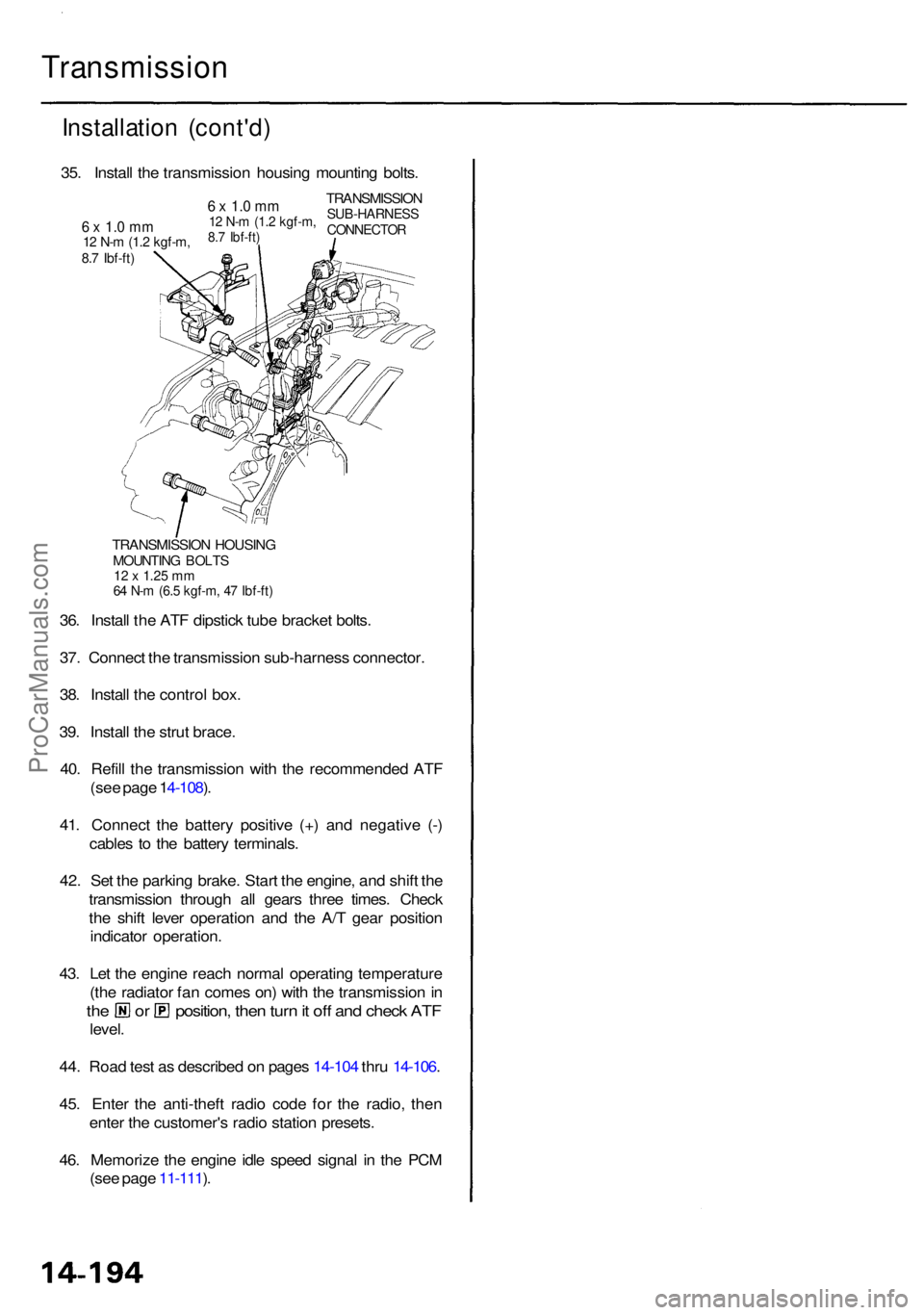
TRANSMISSIO N HOUSIN GMOUNTIN G BOLT S12 x 1.2 5 m m64 N- m (6. 5 kgf-m , 4 7 Ibf-ft )
36. Instal l th e AT F dipstic k tub e bracke t bolts .
37 . Connec t th e transmissio n sub-harnes s connector .
38 . Instal l th e contro l box .
39 . Instal l th e stru t brace .
40 . Refil l th e transmissio n wit h th e recommende d AT F
(se e pag e 1 4-108 ).
41 . Connec t th e batter y positiv e (+ ) an d negativ e (- )
cable s t o th e batter y terminals .
42 . Se t th e parkin g brake . Star t th e engine , an d shif t th e
transmissio n throug h al l gear s thre e times . Chec k
th e shif t leve r operatio n an d th e A/ T gea r positio n
indicato r operation .
43 . Le t th e engin e reac h norma l operatin g temperatur e
(th e radiato r fa n come s on ) wit h th e transmissio n in
th e o r position , the n tur n it of f an d chec k AT F
level .
44 . Roa d tes t a s describe d o n page s 14-10 4 thr u 14-106 .
45 . Ente r th e anti-thef t radi o cod e fo r th e radio , the n
ente r th e customer' s radi o statio n presets .
46 . Memoriz e th e engin e idl e spee d signa l i n th e PC M
(se e pag e 11-111 ).
35
. Instal l th e transmissio n housin g mountin g bolts .
TRANSMISSIO NSUB-HARNES SCONNECTOR
6 x 1. 0 m m12 N- m (1. 2 kgf-m ,8.7 Ibf-ft )6 x 1. 0 m m12 N- m (1. 2 kgf-m ,8.7 Ibf-ft )
ProCarManuals.com
Page 1160 of 1954
Troubleshooting Precautions
ABS Indicator
1. If the system is OK, the ABS indicator goes off 2 seconds after turning the ignition switch ON (II) without starting the
engine, and then comes on again and goes off after 2 seconds. This occurs because the ABS control unit is turned on
by the IG2 power source.
2. The ABS indicator comes on when the ABS control unit detects a problem in the system. However, even though the
system is operating properly, the ABS indicator will come on, under the following conditions.
Only drive wheels rotate
One drive wheel is stuck
Vehicle spin
ABS continues to operate for a long time
Signal disturbance
To determine the actual cause of problem, question the customer about the problem, taking these conditions into con-
sideration.
3. When a problem is detected and the ABS indicator comes on, there are cases when the indicator stays on until the igni-
tion switch is turned OFF, and cases when the indicator goes off automatically when the system returns to normal. For
DTCs 61 and 62, the indicator goes off automatically when the system returns to normal. For all other codes, the indica-
tor stays on until the ignition switch is turned OFF.
4. For DTCs 12, 14, 16, 18, 21, 22, 23, 24, 51, 52 and 53, the indicator goes off when the vehicle is driven again and the sys-
tem is OK after the ignition switch is turned from OFF to ON (II). However, if the DTC is erased, the CPU is reset and the
indicator goes off right after the engine is started if the system is OK.
Diagnostic Trouble Code (DTC)
1. If the CPU cannot be activated and the indicator comes on, the DTC is not memorized.
2. The memory can hold any number of DTCs. However, when the same DTC is detected more than once, the later one is
written over the old one. Therefore, when the same problem is detected repeatedly, it is memorized as 1 DTC.
3. The DTCs are indicated in the order of ascending number, not in the order they occur.
4. The DTCs are memorized in the EEPROM (non-volatile memory). Therefore, the memorized DTCs cannot be canceled
by disconnecting the battery. Perform the specified procedures to erase the DTCs.
Self-diagnosis
1. Self-diagnosis can be classified into 2 categories.
• Initial diagnosis: Performed right after the engine starts and until the ABS indicator goes off.
• Regular diagnosis: Performed right after the initial diagnosis until the ignition switch is turned OFF.
2. When a problem is detected by self-diagnosis, the system.
Turns the fail-safe relay OFF
Turns the solenoid valve OFF
Turns the pump motor OFF
Turns the ABS indicator ONProCarManuals.com