low oil pressure ACURA RL KA9 1996 Service Repair Manual
[x] Cancel search | Manufacturer: ACURA, Model Year: 1996, Model line: RL KA9, Model: ACURA RL KA9 1996Pages: 1954, PDF Size: 61.44 MB
Page 149 of 1954
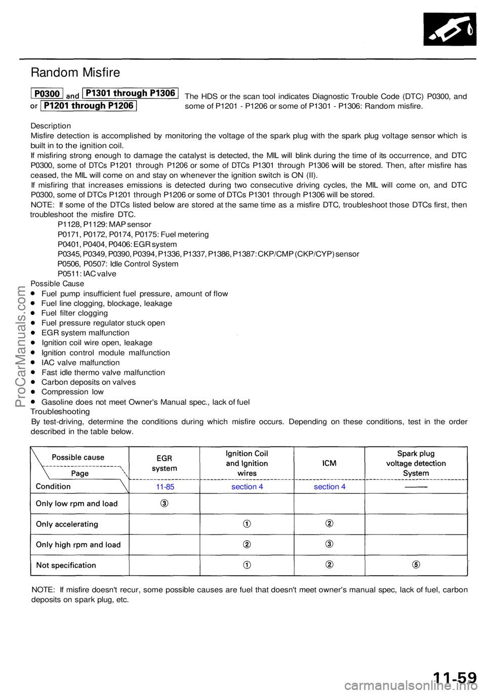
Random Misfir e
The HD S o r th e sca n too l indicate s Diagnosti c Troubl e Cod e (DTC ) P0300 , an d
som e o f P120 1 - P120 6 o r som e o f P130 1 - P1306 : Rando m misfire .
Descriptio n
Misfire detectio n i s accomplishe d b y monitorin g th e voltag e o f th e spar k plu g wit h th e spar k plu g voltag e senso r whic h i s
buil t i n to th e ignitio n coil .
If misfirin g stron g enoug h t o damag e th e catalys t i s detected , th e MI L wil l blin k durin g th e tim e o f it s occurrence , an d DT C
P0300 , som e
of DTC s P120 1 throug h P1206 or som e of DTC s P130 1 throug h P1306 will be stored . Then , after misfir e has
ceased , th e MI L wil l com e o n an d sta y o n wheneve r th e ignitio n switc h is O N (II) .
I f misfirin g tha t increase s emission s i s detecte d during two consecutiv e drivin g cycles , th e MI L wil l com e on , an d DT C
P0300 , som e o f DTC s P120 1 throug h P120 6 o r som e o f DTC s P130 1 throug h P130 6 wil l b e stored .
NOTE : I f som e o f th e DTC s liste d belo w ar e store d a t th e sam e tim e a s a misfir e DTC , troubleshoo t thos e DTC s first , the n
troubleshoo t th e misfir e DTC .
P1128 , P1129 : MA P senso r
P0171 , P0172 , P0174 , P0175 : Fue l meterin g
P0401 , P0404 , P0406 : EG R syste m
P0345 , P0349 , P0390 , P0394 , P1336 , P1337 , P1386 , P1387 : CKP/CM P (CKP/CYP ) senso r
P0506 , P0507 : Idl e Contro l Syste m
P0511 : IA C valv e
Possibl e Caus e
Fuel pum p insufficien t fue l pressure , amoun t o f flo w
Fue l lin e clogging , blockage , leakag e
Fue l filte r cloggin g
Fue l pressur e regulato r stuc k ope n
EG R syste m malfunctio n
Ignitio n coi l wir e open , leakag e
Ignitio n contro l modul e malfunctio n
IA C valv e malfunctio n
Fas t idl e therm o valv e malfunctio n
Carbo n deposit s o n valve s
Compressio n lo w
Gasolin e doe s no t mee t Owner' s Manua l spec. , lac k o f fue l
Troubleshootin g
By test-driving , determin e th e condition s during which misfir e occurs . Dependin g o n thes e conditions , tes t i n th e orde r
describe d i n th e tabl e below .
NOTE : I f misfir e doesn' t recur , som e possibl e cause s ar e fue l tha t doesn' t mee t owner' s manua l spec , lac k o f fuel , carbo n
deposit s o n spar k plug , etc .
11-8 5 sectio n 4 section 4
ProCarManuals.com
Page 492 of 1954
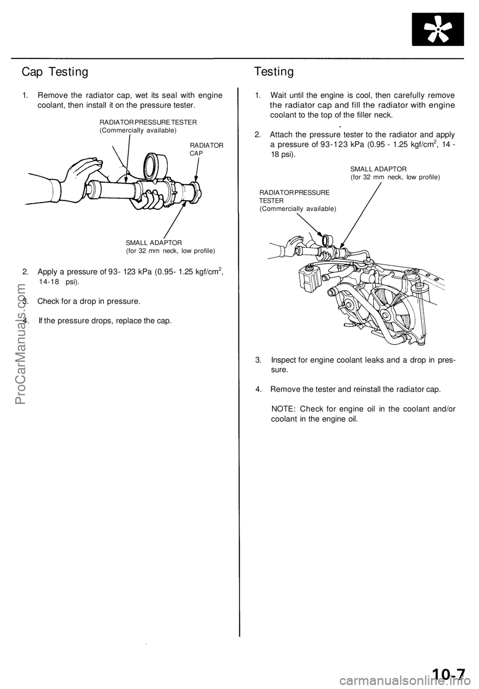
Cap Testing
Testing
1. Remove the radiator cap, wet its seal with engine
coolant, then install it on the pressure tester.
RADIATOR
CAP
2. Apply a pressure of 93- 123 kPa (0.95- 1.25 kgf/cm2,
14-18 psi).
3. Check for a drop in pressure.
4. If the pressure drops, replace the cap.
1. Wait until the engine is cool, then carefully remove
the radiator cap and fill the radiator with engine
coolant to the top of the filler neck.
2. Attach the pressure tester to the radiator and apply
a pressure of 93-123 kPa (0.95 - 1.25 kgf/cm2, 14 -
18
psi).
RADIATOR PRESSURE
TESTER
(Commercially available)
3. Inspect for engine coolant leaks and a drop in pres-
sure.
4. Remove the tester and reinstall the radiator cap.
NOTE: Check for engine oil in the coolant and/or
coolant in the engine oil.
RADIATOR PRESSURE TESTER
(Commercially available)
SMALL ADAPTOR
(for 32 mm neck, low profile)
SMALL ADAPTOR
(for 32 mm neck, low profile)ProCarManuals.com
Page 599 of 1954
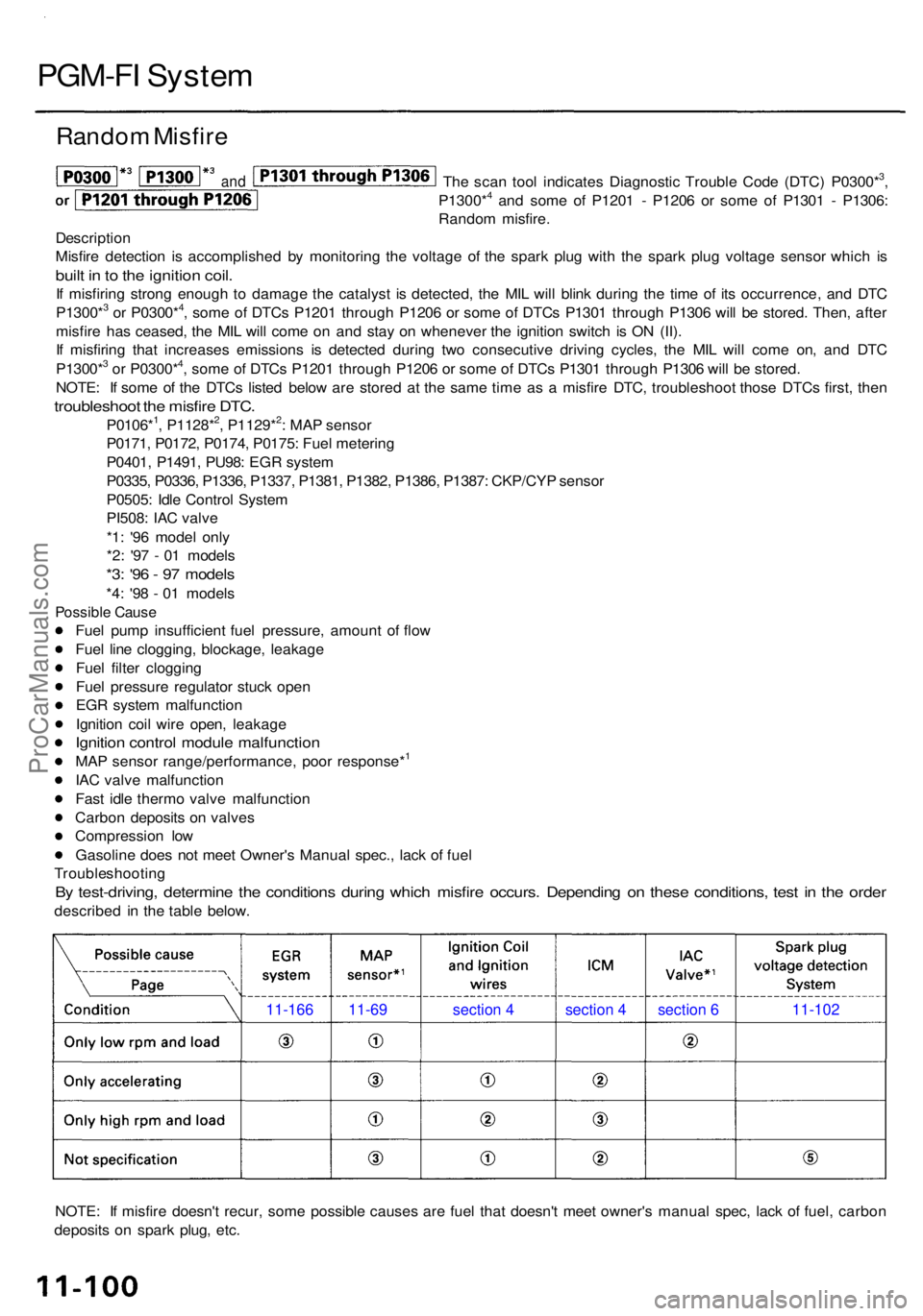
PGM-FI Syste m
Rando m Misfir e
The sca n too l indicate s Diagnosti c Troubl e Cod e (DTC ) P0300*3,
P1300*4 an d som e o f P120 1 - P120 6 o r som e o f P130 1 - P1306 :
Rando m misfire .
Descriptio n
Misfir e detectio n i s accomplishe d b y monitorin g th e voltag e o f th e spar k plu g wit h th e spar k plu g voltag e senso r whic h i s
buil t i n to th e ignitio n coil .
If misfirin g stron g enoug h t o damag e th e catalys t i s detected , th e MI L wil l blin k durin g th e tim e o f it s occurrence , an d DT C
P1300*3 o r P0300*4, som e o f DTC s P120 1 throug h P120 6 o r som e o f DTC s P130 1 throug h P130 6 wil l b e stored . Then , afte r
misfir e ha s ceased , th e MI L wil l com e o n an d sta y o n wheneve r th e ignitio n switc h i s O N (II) .
I f misfirin g tha t increase s emission s i s detecte d durin g tw o consecutiv e drivin g cycles , th e MI L wil l com e on , an d DT C
P1300*
3 o r P0300*4, som e o f DTC s P120 1 throug h P120 6 o r som e o f DTC s P130 1 throug h P130 6 wil l b e stored .
NOTE : I f som e o f th e DTC s liste d belo w ar e store d a t th e sam e tim e a s a misfir e DTC , troubleshoo t thos e DTC s first , the n
troubleshoo t th e misfir e DTC .
P0106*1, P1128*2, P1129*2: MA P senso r
P0171 , P0172 , P0174 , P0175 : Fue l meterin g
P0401 , P1491 , PU98 : EG R syste m
P0335 , P0336 , P1336 , P1337 , P1381 , P1382 , P1386 , P1387 : CKP/CY P senso r
P0505 : Idl e Contro l Syste m
PI508 : IA C valv e
*1 : '9 6 mode l onl y
*2 : '9 7 - 0 1 model s
*3: '9 6 - 9 7 model s
*4: '9 8 - 0 1 model s
Possibl e Caus e
Fuel pum p insufficien t fue l pressure , amoun t o f flo w
Fue l lin e clogging , blockage , leakag e
Fue l filte r cloggin g
Fue l pressur e regulato r stuc k ope n
EG R syste m malfunctio n
Ignitio n coi l wir e open , leakag e
Ignition contro l modul e malfunction
MA P senso r range/performance , poo r response*1
IA C valv e malfunctio n
Fas t idl e therm o valv e malfunctio n
Carbo n deposit s o n valve s
Compressio n lo w
Gasolin e doe s no t mee t Owner' s Manua l spec. , lac k o f fue l
Troubleshootin g
By test-driving , determin e th e condition s durin g whic h misfir e occurs . Dependin g o n thes e conditions , tes t i n th e orde r
describe d i n th e tabl e below .
NOTE : I f misfir e doesn' t recur , som e possibl e cause s ar e fue l tha t doesn' t mee t owner' s manua l spec , lac k o f fuel , carbo n
deposit s o n spar k plug , etc .
11-166 11-69 section 4 section 4 section 6 11-102
and
ProCarManuals.com
Page 1488 of 1954
A/C Servic e Tip s an d Precaution s
The ai r conditione r syste m uses HFC-134 a (R-134a) refrigeran t and polyalkyleneglyco l (PAG ) refrigeran t oil*, whic h are no t
compatibl e with CFC-1 2 (R-12) refrigeran t and minera l oil . Do no t us e R-1 2 refrigeran t or minera l oil i n thi s system , and d o
no t attemp t t o us e R-1 2 servicin g equipment ; damag e to th e ai r conditione r syste m o r you r servicin g equipmen t wil l result .
* DENS O ND-OI L 8
P/ N 38897-PR7-A01AH : 12 0 m ( 4 fl-oz , 4. 2 Imp-oz )
P/N38899-PR7-A01 : 4 0 m ( 1 1/ 3 fl-oz , 1. 4 Imp-oz )
Use onl y servic e equipmen t tha t i s U.L.-liste d an d i s certifie d t o mee t th e requirement s o f SA E J221 0 t o remov e R-134 a
from th e ai r conditione r system .
CAUTION : Exposur e t o ai r conditione r refrigeran t an d lubrican t vapo r o r mis t ca n irritat e eyes , nos e an d throat . Avoi d
breathin g th e ai r conditione r refrigeran t an d lubrican t vapo r o r mist .
I f accidenta l syste m discharg e occurs , ventilat e wor k are a befor e resumin g service .
R-134 a servic e equipmen t o r vehicl e ai r conditione r system s shoul d no t b e pressur e teste d o r lea k teste d wit h compresse d
air.
Som e mixture s o f ai r an d R-134 a hav e bee n show n to b e combustibl e a t elevate d pressure s an d ca n resul t
i n fir e o r explosio n causin g injur y o r propert y damage . Neve r us e compresse d ai r t o pressur e tes t R-134 a servic e equip -
men t o r vehicl e ai r conditione r systems .
Additiona l healt h an d safet y informatio n ma y b e obtaine d fro m th e refrigeran t an d lubrican t manufacturers .
1 . Alway s disconnec t th e negativ e cabl e fro m th e batter y wheneve r replacin g ai r conditionin g parts .
2 . Kee p moistur e an d dus t ou t o f th e system . Whe n disconnectin g an y lines , plu g o r ca p th e fitting s immediately ; don' t
remov e th e cap s o r plug s unti l jus t befor e yo u reconnec t eac h line .
3 . Befor e connectin g an y hos e o r line , appl y a fe w drop s o f refrigeran t oi l t o th e O-ring .
4 . Whe n tightenin g o r loosenin g a fitting , us e a secon d wrenc h t o suppor t th e matchin g fitting .
5 . Whe n dischargin g th e system , us e a R-134 a refrigeran t recovery/recycling/chargin g station ; don' t releas e refrigeran t
int o th e atmosphere .
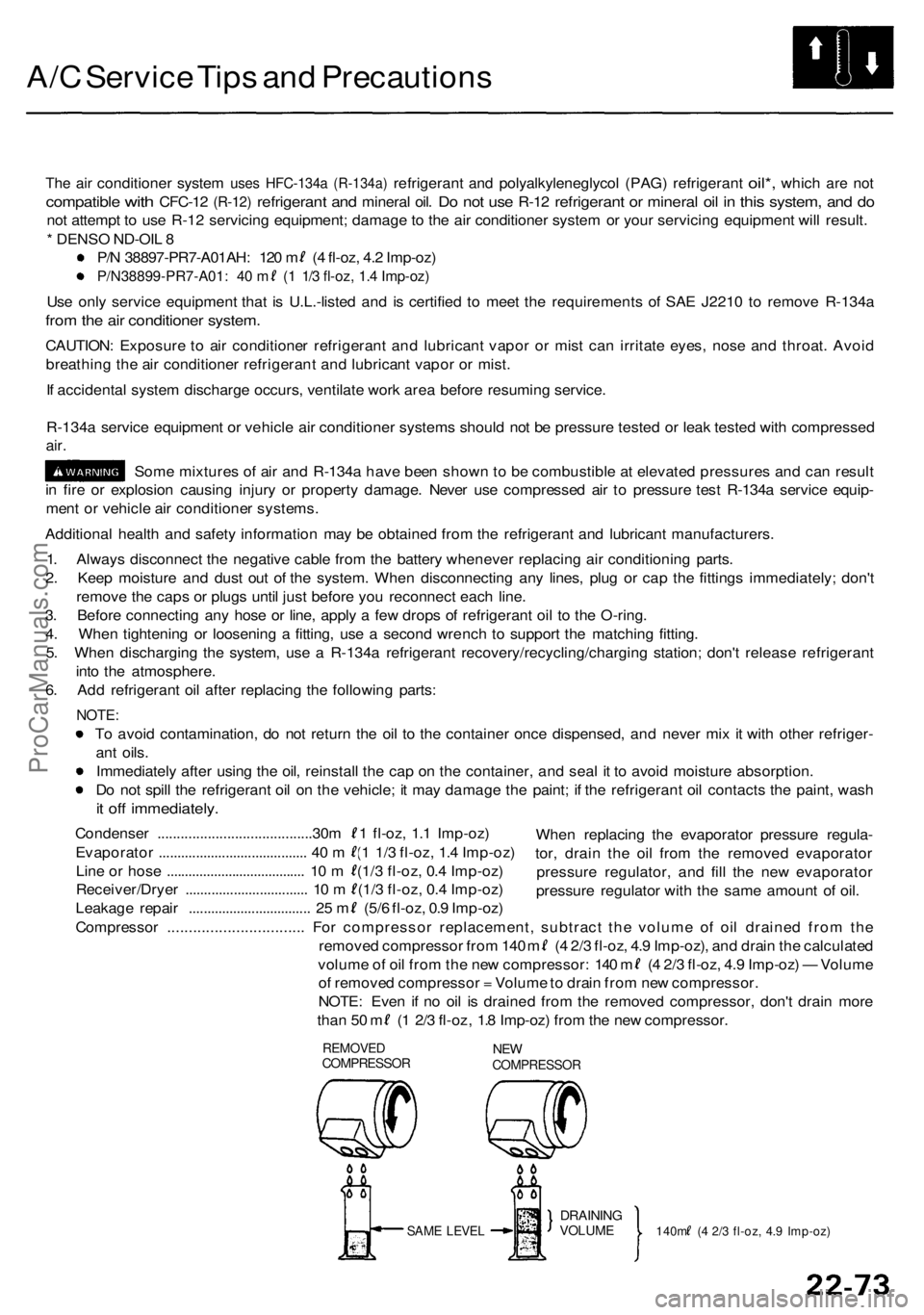
6 . Ad d refrigeran t oi l afte r replacin g th e followin g parts :
NOTE :
To avoi d contamination , d o no t retur n th e oi l t o th e containe r onc e dispensed , an d neve r mi x i t wit h othe r refriger -
an t oils .
Immediatel y afte r usin g th e oil , reinstal l th e ca p o n th e container , an d sea l i t t o avoi d moistur e absorption .
D o no t spil l th e refrigeran t oi l o n th e vehicle ; i t ma y damag e th e paint ; i f th e refrigeran t oi l contact s th e paint , was h
it of f immediately .
When replacin g th e evaporato r pressur e regula -
tor , drai n th e oi l fro m th e remove d evaporato r
pressur e regulator , an d fil l th e ne w evaporato r
pressur e regulato r wit h th e sam e amoun t o f oil .
Condense
r ........................................30 m ( 1 fl-oz , 1. 1 Imp-oz )
Evaporato r ....................................... . 4 0 m (1 1/ 3 fl-oz , 1. 4 Imp-oz )
Lin e o r hos e ..................................... . 1 0 m (1/ 3 fl-oz , 0. 4 Imp-oz )
Receiver/Drye r ................................ . 1 0 m (1/ 3 fl-oz , 0. 4 Imp-oz )
Leakage repai r ................................ . 2 5 m (5/ 6 fl-oz , 0. 9 Imp-oz )
Compresso r ............................... . Fo r compresso r replacement , subtrac t th e volum e o f oi l draine d fro m th e
remove d compresso r fro m 14 0 m ( 4 2/ 3 fl-oz , 4. 9 Imp-oz) , an d drai n th e calculate d
volume o f oi l fro m th e ne w compressor : 14 0 m ( 4 2/ 3 fl-oz , 4. 9 Imp-oz ) — Volum e
o f remove d compresso r = Volum e to drai n fro m ne w compressor .
NOTE : Eve n i f n o oi l i s draine d fro m th e remove d compressor , don' t drai n mor e
than 5 0 m ( 1 2/ 3 fl-oz , 1. 8 Imp-oz ) fro m th e ne w compressor .
REMOVEDCOMPRESSO RNEWCOMPRESSO R
SAME LEVE LDRAININ GVOLUME140m ( 4 2/ 3 fl-oz , 4. 9 Imp-oz )
ProCarManuals.com
Page 1490 of 1954
A/C System Service
Recovery
Use only service equipment that is U.L.-listed and is cer-
tified to meet the requirements of SAE J2210 to remove
HFC-134a (R-134a) from the air conditioner system.
CAUTION: Exposure to air conditioner refrigerant and
lubricant vapor or mist can irritate eyes, nose and
throat. Avoid breathing the air conditioner refrigerant
and lubricant vapor or mist.
If accidental system discharge occurs, ventilate work
area before resuming service.
R-134a service equipment or vehicle air conditioner sys-
tems should not be pressure tested or leak tested with
compressed air.
Some mixtures of air and R-134a have been
shown to be combustible at elevated pressures and can
result in fire or explosion causing injury or property dam-
age. Never use compressed air to pressure test R-134a
service equipment or vehicle air conditioner systems.
Additional health and safety information may be obtained
from the refrigerant and lubricant manufacturers.
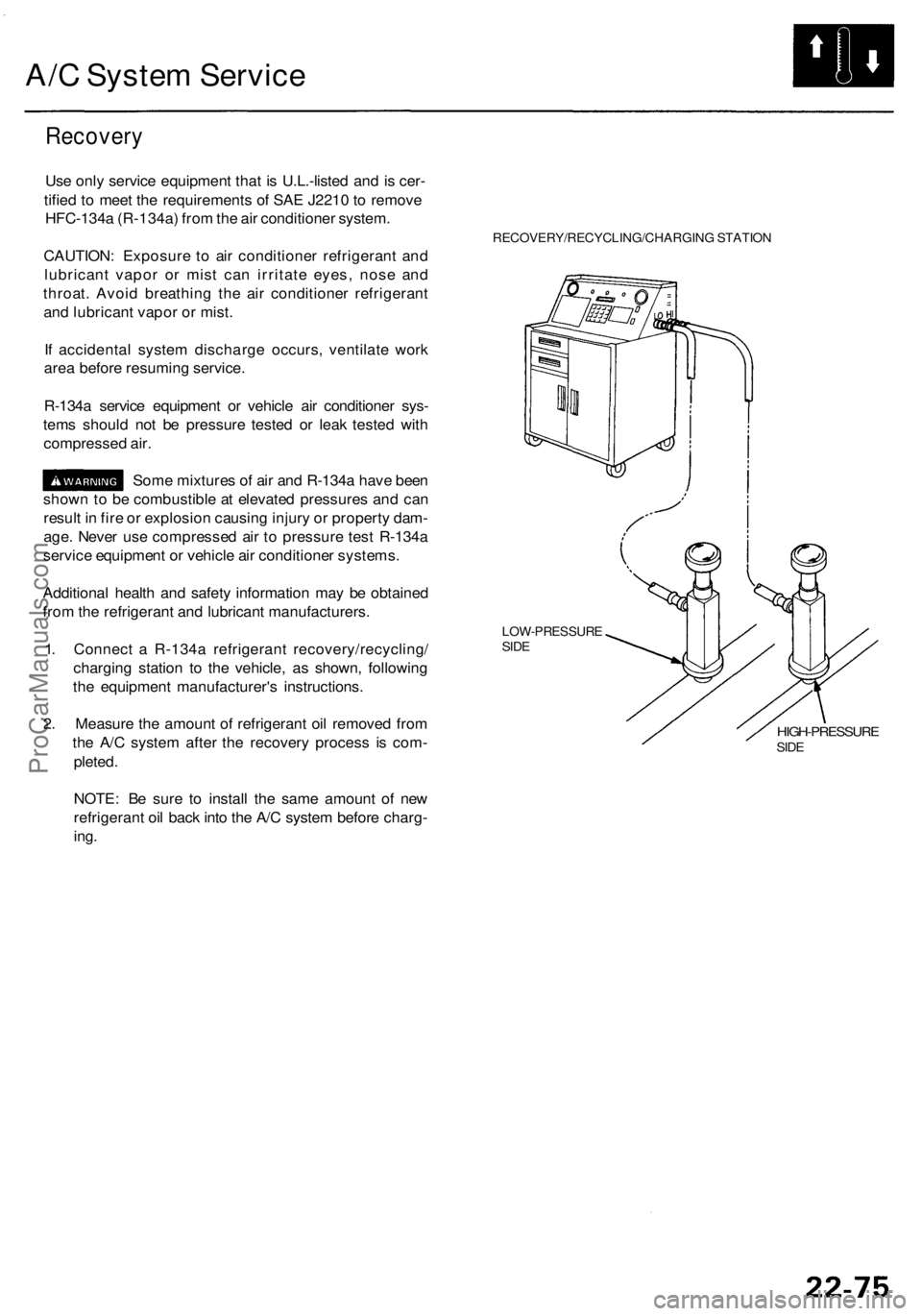
1. Connect a R-134a refrigerant recovery/recycling/
charging station to the vehicle, as shown, following
the equipment manufacturer's instructions.
2. Measure the amount of refrigerant oil removed from
the A/C system after the recovery process is com-
pleted.
RECOVERY/RECYCLING/CHARGING STATION
LOW-PRESSURE
SIDE
HIGH-PRESSURE
SIDE
NOTE: Be sure to install the same amount of new
refrigerant oil back into the A/C system before charg-
ing.ProCarManuals.com
Page 1493 of 1954
A/C Syste m Servic e
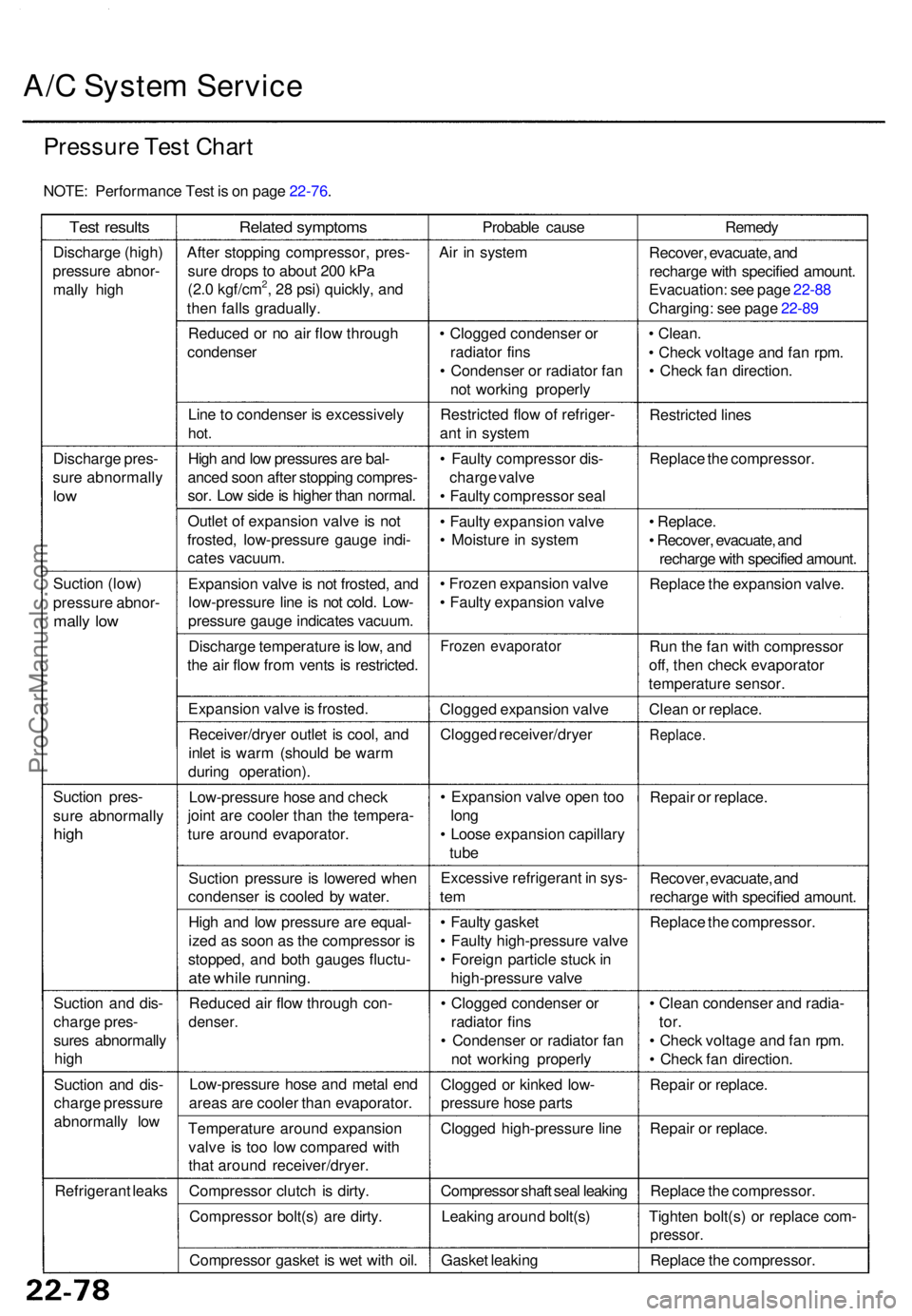
Pressur e Tes t Char t
NOTE : Performanc e Tes t i s o n pag e 22-76 .
Test result s
Discharg e (high )
pressur e abnor -
mall y hig h
Discharg e pres -
sur e abnormall y
low
Suctio n (low )
pressur e abnor -
mally lo w
Suctio n pres -
sur e abnormall y
high
Suctio n an d dis -
charg e pres -
sure s abnormall y
hig h
Suctio n an d dis -
charg e pressur e
abnormall y lo w
Refrigeran t leak s
Relate d symptom s
After stoppin g compressor , pres -
sur e drop s t o abou t 20 0 kP a
(2. 0 kgf/cm
2, 2 8 psi ) quickly , an d
the n fall s gradually .
Reduce d o r n o ai r flo w throug h
condense r
Lin e to condense r i s excessivel y
hot.
Hig h an d lo w pressure s ar e bal -
ance d soo n afte r stoppin g compres -
sor . Lo w sid e is highe r tha n normal .
Outle t o f expansio n valv e is no t
frosted , low-pressur e gaug e indi -
cate s vacuum .
Expansio n valv e is no t frosted , an d
low-pressur e lin e is no t cold . Low -
pressur e gaug e indicate s vacuum .
Discharg e temperatur e is low , an d
th e ai r flo w fro m vent s i s restricted .
Expansio n valv e is frosted .
Receiver/drye r outle t i s cool , an d
inle t i s war m (shoul d b e war m
durin g operation) .
Low-pressur e hos e an d chec k
join t ar e coole r tha n th e tempera -
tur e aroun d evaporator .
Suctio n pressur e is lowere d whe n
condense r i s coole d b y water .
Hig h an d lo w pressur e ar e equal -
ize d a s soo n a s th e compresso r i s
stopped , an d bot h gauge s fluctu -
ate whil e running .
Reduce d ai r flo w throug h con -
denser .
Low-pressur e hos e an d meta l en d
area s ar e coole r tha n evaporator .
Temperatur e aroun d expansio n
valv e i s to o lo w compare d wit h
tha t aroun d receiver/dryer .
Compresso r clutc h i s dirty .
Compresso r bolt(s ) ar e dirty .
Compresso r gaske t i s we t wit h oil . Probabl
e caus e
Ai r i n syste m
• Clogge d condense r o r
radiato r fin s
• Condense r o r radiato r fa n
no t workin g properl y
Restricte d flo w o f refriger -
an t i n syste m
• Fault y compresso r dis -
charg e valv e
• Fault y compresso r sea l
• Fault y expansio n valv e
• Moistur e in syste m
• Froze n expansio n valv e
• Fault y expansio n valv e
Froze n evaporato r
Clogged expansio n valv e
Clogge d receiver/drye r
• Expansio n valv e ope n to o
lon g
• Loos e expansio n capillar y
tub e
Excessiv e refrigeran t i n sys -
tem
• Fault y gaske t
• Fault y high-pressur e valv e
• Foreig n particl e stuc k in
high-pressur e valv e
• Clogge d condense r o r
radiato r fin s
• Condense r o r radiato r fa n
no t workin g properl y
Clogge d o r kinke d low -
pressur e hos e part s
Clogge d high-pressur e lin e
Compresso r shaf t sea l leakin g
Leakin g aroun d bolt(s )
Gaske t leakin g Remed
y
Recover , evacuate , an d
recharg e wit h specifie d amount .
Evacuation : se e pag e 22-8 8
Charging : se e pag e 22-8 9
• Clean .
• Chec k voltag e an d fa n rpm .
• Chec k fa n direction .
Restricte d line s
Replac e th e compressor .
• Replace .
• Recover , evacuate , an d
recharg e wit h specifie d amount .
Replac e th e expansio n valve .
Ru n th e fa n wit h compresso r
off , the n chec k evaporato r
temperatur e sensor .
Clea n o r replace .
Replace .
Repair o r replace .
Recover , evacuate , an d
recharg e wit h specifie d amount .
Replac e th e compressor .
• Clea n condense r an d radia -
tor.
• Chec k voltag e an d fa n rpm .
• Chec k fa n direction .
Repai r o r replace .
Repai r o r replace .
Replac e th e compressor .
Tighte n bolt(s ) o r replac e com -
pressor .
Replace th e compressor .
ProCarManuals.com